GRAS 12AA User manual

Instruction Manual

Revision 20 05 2019
Power Module
Type 12AA

G.R.A.S. Sound & Vibration
CONTENTS
1. Introduction and Description ......................................4
1.1 Polarization Voltage ................................................4
1.2 PreamplierVoltageSupplies . . . . . . . . . . . . . . . . . . . . . . . . . . . . . . . . . . . . . . . . . 4
1.3 SignalConditioning . . . . . . . . . . . . . . . . . . . . . . . . . . . . . . . . . . . . . . . . . . . . . . . . . 6
FrequencyResponse ......................................................6
Gain. . . . . . . . . . . . . . . . . . . . . . . . . . . . . . . . . . . . . . . . . . . . . . . . . . . . . . . . . . . . . . . . . . . . 6
Direct-modeCoupling ......................................................6
1.4 SysCheck(SystemCheck) . . . . . . . . . . . . . . . . . . . . . . . . . . . . . . . . . . . . . . . . . . . 6
1.5 PowerSupplies . . . . . . . . . . . . . . . . . . . . . . . . . . . . . . . . . . . . . . . . . . . . . . . . . . . . 6
1.6 Input/Output ......................................................6
2. External Features ................................................7
2.1 Front Panel . . . . . . . . . . . . . . . . . . . . . . . . . . . . . . . . . . . . . . . . . . . . . . . . . . . . . . . 7
2.2 Rear Panel .......................................................8
3. Internal Features . . . . . . . . . . . . . . . . . . . . . . . . . . . . . . . . . . . . . . . . . . . . . . . . . 9
3.1 BatteryPack ......................................................9
3.2 User-servicableSwitches ............................................9
4. Operation . . . . . . . . . . . . . . . . . . . . . . . . . . . . . . . . . . . . . . . . . . . . . . . . . . . . . . 11
4.1 BatteriesandExternalPower . . . . . . . . . . . . . . . . . . . . . . . . . . . . . . . . . . . . . . . . 11
4.2 PolarizationVoltageandPreamplierVoltage ........................... 11
4.3 FilterSettingsandDirectMode. . . . . . . . . . . . . . . . . . . . . . . . . . . . . . . . . . . . . . . 11
4.4 SysCheck(SystemCheck) . . . . . . . . . . . . . . . . . . . . . . . . . . . . . . . . . . . . . . . . . . 11
5. Service and Repair ..............................................12
6. Specications ..................................................13

G.R.A.S. Sound & Vibration
Power Module Type 12AA - Page 4
1. Introduction and Description
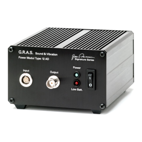
TheG.R.A.S.PowerModuleType12AA(Fig.1.1)isadual-channelpowersupplyforpreampli-
ersusedwithcondensermicrophones.Itisforgeneraluseinacousticmeasurementsaswell
asforintensitymeasurements;bothinthelaboratoryandintheeld.
Itprovides:
• apolarizationvoltagefortwocondensermicrophones
• avoltagesupplyforpoweringuptotwomicrophonepreampliers.
• achoiceofsignalconditioning.
AblockdiagramofitsmaincomponentsisshowninFig.1.2.
1.1 Polarization Voltage
Thepolarizationvoltagecanbesettoeither0Vor200Vviaaninternalswitch(seesection3.2).
Use:
• 0Vforprepolarizedmicrophones,and
• 200Vforexternally-polarizedmicrophones(defaultsetting)
1.2 PreamplierVoltageSupplies
Thepreampliervoltagesupplycanbesettoeither28VDCor120VDCviaaninternalswitch
(seesection3.2).Use:
• 28Vforminimumpowerconsumption(defaultsetting),and
• 120Vformaximumdynamicrange
Fig. 1.1 Power Module Type 12AA

G.R.A.S. Sound & Vibration
Power Module Type 12AA - Page 5
Fig. 1.2 Block diagram of the Type 12AA

G.R.A.S. Sound & Vibration
Power Module Type 12AA - Page 6
1.3 Signal Conditioning
1.3.1 Frequency Response
Thefrequencyresponsecanbesettooneofthefollowingviainternalswitches(seesec-
tion3.2):
• Linear
• A-weighted
viastandardA-weightingltersfulllingtherequirementsofIECStandard60651“Sound
LevelMeters”Type0.
• High-pass
via3-poleButterworthhigh-passlterswitha–1dBcutoffatafrequencyof20Hz
Whicheveroneisselectedisappliedtobothchannels.
1.3.2 Gain
Thegainofeachchannelcanbesetindependentlytooneofthefollowing:
• –20dB
• 0 d B
• 20dB
• 40dB
1.3.3 Direct-mode Coupling
Finally,themicrophonesignalfromeachpreampliercanbecoupleddirectlywithitsBNC
outputsocketviaindependentinternalswitches(seesection3.2),thusby-passingallsignal
conditioning.Forintensitymeasurements,whereextremelygoodphasematchingisrequired,
useDirectmodeinbothchannels.Also,tofullyusethedynamicrangepossiblewith120Vpre-
ampliersupply,useDirectmode,seealsoSection4.2.
1.4 SysCheck (System Check)
TheType12AAhasabuilt-in1000HzSysCheckgeneratorforverifyingthestabilityofthecom-
pletemeasuringsystemincludingthemicrophone.
Thesignallevelfromthegeneratorcanbepre-adjustedbeforeitisappliedtothemeasurement
set-up.Asystemcheckcanbeactivatedlocallyviaapushbuttononthefrontpanel,orremotely
viaaMiniJacksocketontherearpanel.
SysCheck(orsimilartechnique)canbeusedwithpreamplierssupportingthisfeature,e.g.the
G.R.A.S.preampliersType26AJandType26AL.
1.5 Power Supplies
TheType12AAcanrunoninternalbatterieswithabatterylifeofapproximately10hoursusing
G.R.A.S.preampliers,orfromanexternalpowersupplyof12-18VDC,e.g.themains/line
adapterincludedwiththeType12AA.
1.6 Input/Output
TheType12AAhastwo7-pinLEMOinputconnectors(AandB)formicrophonepreampliers
suchastheG.R.A.S.PreampliersTypes26AM,26ACand26AK.Fig.2.2showsthewiringdia-
gramoftheseinputconnectorswhicharealsocompatiblewitharangeofmicrophonepreampli-
ersfromothersupplierssuchasNorsonic,L&DandBrüel&Kjær.
Thecorrespondingoutputsforthetwo7-pinLEMOinputconnectorsareavailableviastandard
BNCsockets(AandB)fordirectusewithanalyzers,voltmeters,oscilloscopesetc.

G.R.A.S. Sound & Vibration
Power Module Type 12AA - Page 7
2. External Features
2.1 Front Panel
Thefrontpanelhasthefollowingfeatures(seeFig.2.1)
• Powerswitchandbattery-levelmeter.
Ifthepowersupplyiscorrect,thebattery-levelmeterwillpointtothegreenzone.Ifitpoints
totheredzone,eitherthebatteriesarelowandshouldbechanged(seesection3.1)orthe
externalDCsupplyvoltageistoolow.
• SysCheckpush-button.
Pressandholdtoactivatethe1000HzSysCheckgenerator.Thesignalfromthegenerator
willbeavailableonpin1(seeFig.2.2)ofeachPreamplierInputsocket.
• SysCheckadjustmentpotentiometers(Ch.A/Ch.B).
UseasmallscrewdrivertoadjusttheleveloftheSysChecksignalavailableonpin1(see
Fig.2.2)ofthePreamplierInputsocket.Adjustmentisindividualforeachchanneland
rangesfrom0to5.6VRMS.
• PreamplierInputChannels(In. A/In. B).
7-pinLEMOinputconnectorformicrophonepreamplier.WiringdiagramshowninFig.2.2
• GainswitchesandOverloadLEDs(In. A/In. B).
Adjustthegainofeachchannel(attenuator/amplier)individuallytosuitrequirementsand
withoutoverloadingtheinputcircuits(OverloadLEDlightsup).Gainsettingsarefrom
–20dBto+40dBin20dBsteps.DisabledifDirectmodeisselected(seesection3.2).
Whensetto+40dB,theOverloadLEDlightsupwithopeninput.Thisisnormal.
Fig. 2.1 Front panel of the Power Module Type 12AA
Battery-levelindicator
SysCheckpushbutton
PreamplierinputCh.A
PreamplierinputCh.B
Power,On/Offtoggleswitch
OverloadLEDCh.A
SysCheckadjustmentCh.A SysCheckadjustmentCh.B
OverloadLEDCh.B
GainCh.A,rotaryswitch
(-20,0,+20and+40dB)
GainCh.B,rotaryswitch
(-20,0,+20and+40dB)

G.R.A.S. Sound & Vibration
Power Module Type 12AA - Page 8
2.2 Rear Panel
Therearpanelhasthefollowingfeatures(seeFig.2.3)
• Twist/releaseholderfor315mA,250Vlow-impedance(<1.5Ω)fuse.
• Inputsocketforanexternalpowersupplyof12 - 18 V DC;centrepin+terminal.Theuseof
anexternalpowersupplyautomaticallydisablespowerfromthebatteries.
• Remote SysCheck Start.
MiniJackinputforremoteSysCheckstart.Applya+DCvoltageof4-9V(e.g.fromthe
RS232outputofacomputer)toactivatetheSysCheckgenerator;centrepin+terminal.
• Ouputchannels(Out A/Out B).
BNCsocketfortheoutputsignaleitherviasignalconditioningordirectlyfromthemicro-
phonepreamplier.
• Lockingscrew
Unscrewtoremovebaseplateandgainaccesstointernalsettingswitches.
Fig. 2.3 Rear panel of the Power Module Type 12AA
Fig. 2.2 7-pin LEMO female socket 1B (external view)
Fuse315mA(<1.5Ω),250V
Inputforexternalpowersupply
12-18VDC
RemoteSysCheckstart
OutputCh.A
OutputCh.B
Lockingscrewfor
baseplate

G.R.A.S. Sound & Vibration
Power Module Type 12AA - Page 9
3. Internal Features
Note:switchtheType12AAoffanddisconnectitfromanyexternalpowersupplybeforeremov-
ingthebaseplateforanyreason.Afterwardsreplacethebaseplate.
Thebatterypackanduser-servicableswitchesarecontainedwithinthecabinetoftheType
12AA.Togainaccesstothese,rstremovetheknurledlockingscrew(seeFig.2.3)andslide
thebaseplateoff.
Fig. 3.1 Showing the battery pack of the Power Module Type 12AA
3.1 Battery Pack
Takeoutthebatterytray(Fig.3.1)andreplaceallthebatteries(10xLR6(AA)standardalkaline
cells),makingsurethatthepolarityisasindicatedonthebatterytray.
3.2 User-servicable Switches
The(internal)user-servicableslideswitchesareshowninFig.3.2.
• Filter selection(applicabletobothchannels,disabledifDirectmodeisselected):3-posi-
tionsignal-conditioningswitch;
- Lin.
routesthesignalthroughtheamplieralone
- H.P.
routesthesignalthroughtheamplierandthe20Hzhigh-passlter(e.g.tosupress
infra-sound)
- A-w
routesthesignalthroughtheamplierandtheA-weightingnetwork
• Direct mode select:2-positionswitch(oneforeachchannel):
- Dir.
selectstheDirectmodeandby-passestheFilter selectionswitchforthischannel
andtheampliercircuit(seeabove)
- Ampl.
enablestheFilter sectionswitchforthischannelandtheampliercircuit(seeabove)
• Preampliersupplyselectpairofswitches:
- Polarization voltage2-positionswitch(applicabletobothchannels)selects:
0 V forprepolarized(electret)microphones
or 200 V forexternally-polarizedmicrophones
- Supply voltage2-positionswitch(applicabletobothchannels)selects:
120 V formaximumdynamicrange
or 28 V forminimumpowerconsumption

G.R.A.S. Sound & Vibration
Power Module Type 12AA - Page 10
Fig. 3.2 Showing the internal switches of the Power Module Type 12AA
Filterselection
• Linear
• HighPass
• A-weighting
Ch.B
• Directmode
• Ampliermode
Ch.A
• Directmode
• Ampliermode
Polarization voltage
• 0 V
• 200 V
Supplyvoltage
• 120 V
• 28 V
Note:
SwitchoffthePower
Modulebeforechang-
inganypreamplier
power settings

G.R.A.S. Sound & Vibration
Power Module Type 12AA - Page 11
4. Operation
4.1 Batteries and External Power
TheType12AAcanbepoweredeitherbyinternalbatteries(Fig.3.1)orfromanexternalpower
supplyviatheDCinputontherearpanel(Fig.2.3).Ifanexternalpowersupplyisused,thebat-
terieswithintheunitwillbeautomaticallydisconnected.Externalpowershouldbe12-18VDC,
typicallyfromthemains/lineadaptorincludedwiththeType12AA.
WhenevertheType12AAisswitchedon,thebattery-levelmeteronthefrontpanel(Fig.2.1)
shouldalwayspointtothegreenzonetoensurecorrectoperation.Ifitpointstotheredzone,
eitherthebatteriesarelowandshouldbechanged(seesection3.1)ortheexternalDCsupply
voltage is too low.
4.2 PolarizationVoltageandPreamplierSupplyVoltage
Polarizationvoltagecanbeswitchedfrom200Vto0V(seesection3.2).Use200Vforstandard
externally-polarizedcondensermicrophones,and0Vforprepolarized(electret)microphones.
Preampliersupplyvoltagecanbeswitchedfrom28Vor120V.Use28Vforminimisingpower
consumption,itisalsosufcientformostapplicationsbutlimitsthedynamicrangeofthemicro-
phonepreampliersusedwiththeType12AA.Use120Vtoutilisethefulldynamicrangeofthe
microphonepreamplier.InthiscasethedynamicrangewillbedeterminedbytheType12AA
whichshouldbeswitchedtoitsDirectmode(section3.2)oritsGainswitchedto–20dBtoavoid
overload.
4.3 Filter Settings and Direct Mode
Therearethreeinternalslideswitches(section3.2),twoforselectingDir.(Direct)orAmpl.
(Amplier)modeforthetwochannelsandoneforselectingwhichAmpliermode,viz.(a) Lin.
(linear),(b) A-w(A-weighting)or(c) H.P.(high-pass)ltering.
IntheDirectmode,allamplicationandlteringcircuitsareby-passedforthatchannel;the
signalgoesdirectlyfromLEMOinputtoBNCoutput.
DirectmodeispreferablewhenusingtheType12AAinintensitymeasurements,whichrequire
extremelyaccuratephaseresponseinbothchannels.Inthismode,thecorrespondingGain
switchonthefrontpanelhasnoeffectanditsoverloadLEDregistersnothing.
IntheAmpliermodetheinputsignalsareampliedinternallyandpassedthroughaselected
lter.UseLin.ifnolteringisrequired.UseA-wifAweightingisrequiredbythemeasurement
standard.UseH.P.iflowfrequencies(below20Hz)aretobesuppressed.
4.4 SysCheck (System Check)
SysCheck(orsimilartechnique)canbeusedwithpreamplierssupportingthisfeature,e.g.the
G.R.A.S.preampliersType26AJandType26AL.
UseSysChecktoverifythestabilityofacompletemeasurementset-up.Ifthesignalregistered
bythemeasuringequipmentasaresultofactivatingaSysCheckremainsunchanged,then
systemstability(includingthemicrophone)canbeassumed.

G.R.A.S. Sound & Vibration
Power Module Type 12AA - Page 12
5. Service and Repair
Repairsshouldbecarriedoutonlybyqualiedpersonal.ThePowerModuleType12AAshould
notbedismantledwithpoweronbecauseofhigh-voltagecircuits.

G.R.A.S. Sound & Vibration
Power Module Type 12AA - Page 13
6. Specications
2 channels (A and B), each comprising:
Inputsocket: 7-pinLEMO1Bfemale
Outputsocket: BNCcoaxial
Gain:
–20dBto+40dBin20dBsteps,andDirectmode
Output-voltages:
Preampliersupply: 28Vor120V
Polarizationvoltage: 0Vor200V
Gain error:
<0.2dB
Frequency response (Lin setting):
3.5Hz-200kHz: ±1.0dB
2Hz-250kHz: ±3.0dB
Channel separation:
20Hz-20kHz: >65dB
Inherent noise:
(20Hz-20kHzwithinputgrounded)
A-weighted: <1µV
Lin: <1.6µV
(20Hz-20kHzwithG.R.A.S.preamplierand20pFdummymicrophone)
A-weighted: <3,2µV
Lin: <5.7µV
(valuesvalidfor+20dBand+40dBgainre.input)
A-weightinglters:
CompliantwithIEC60651Type0
High-passlter:
3-poleButterworth,–1dBat20Hz
Output impedance:
30Ω
Power supply:
10xLR6(AA)standardalkalinecells,or
DCmains/lineadaptersupply: 12V-18V
Power consumption:
WithoneG.R.A.Spreamplierusing:-
120V: 190mA
28V: 160mA
Fuse:
315mA(lowimpedance<1.5Ω),250V

G.R.A.S. Sound & Vibration
Power Module Type 12AA - Page 14
Battery life (valid for Alkaline cells at 23°C) for:-
120Vsupply: ≈8hours
28Vsupply: ≈10hours
Operating temperature range:
–10°Cto+50°C
Dimensions:
(1/12ofastandard19-inchrack)
Height: 132.6mm(5¼in)
Width: 34.6mm(1.3in)
Depth: 196.0mm(7.7in)
Weight: 770g(1.69lbs)
Accessories included:
Mains/lineadapter:
Europe: AB0002
USA: AB0003
Accessories available:
AK0040 19-inchRack-mountingSystem
WEEEdirective:
2002/96/EC
CEmarkingdirective:
93/68/EEC
Manufacturedtoconformwith:
RoHSdirective:
2002/95/EC
G.R.A.S. Sound & Vibration continually strives to improve the quality of our products for our customers; therefore, the
specifications and accessories are subject to change.
Table of contents
Other GRAS Control Unit manuals