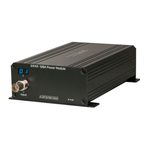
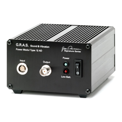
GRAS 12AB User manual

Instruction Manual
12AB 2-Channel Power Module for
GRAS Intensity Probes
LI0113 – 12 February 2008

CONTENTS
1. Introduction and Description ......................................3
1.1 Polarization Voltage ................................................3
1.2 PreamplierVoltageSupplies . . . . . . . . . . . . . . . . . . . . . . . . . . . . . . . . . . . . . . . . . 3
1.3 PowerSupplies . . . . . . . . . . . . . . . . . . . . . . . . . . . . . . . . . . . . . . . . . . . . . . . . . . . . 4
1.4 Input/Output ......................................................4
2. External Features ................................................5
2.1 Front Panel . . . . . . . . . . . . . . . . . . . . . . . . . . . . . . . . . . . . . . . . . . . . . . . . . . . . . . . 5
2.2 Rear Panel .......................................................7
3. Internal Features . . . . . . . . . . . . . . . . . . . . . . . . . . . . . . . . . . . . . . . . . . . . . . . . . 8
3.1 Battery Pack ......................................................8
3.2 User-servicableSwitches ............................................8
4. Operation . . . . . . . . . . . . . . . . . . . . . . . . . . . . . . . . . . . . . . . . . . . . . . . . . . . . . . . 9
4.1 BatteriesandExternalPower . . . . . . . . . . . . . . . . . . . . . . . . . . . . . . . . . . . . . . . . . 9
4.2 PolarizationVoltageandPreamplierVoltage ............................9
5. Service and Repair ..............................................10
6. Specications ..................................................11

Intensity Power Module Type 12AB - Page 3
Fig. 1.1 Intensity Power Module Type 12AB
* FactorysettingsforusewithGRASSoundIntensityProbetype50AIversionB
1. Introduction and Description
TheG.R.A.S.IntensityPowerModuleType12AB(Fig.1.1)isatwo-channelpowersupplyfor
usewithversionsB,CandDoftheG.R.A.S.SoundIntensityProbeType50AI.
TheType12ABisbuiltintoasturdyanodizedaluminiumcabinetandcanbepoweredeitherby
internalstandardbatteriesoranexternalDCsupply(12V-18V),e.g.amains/lineadapter.
AblockdiagramofitsmaincomponentsisshowninFig.1.2.
1.1 Polarization Voltage
Thepolarizationvoltagecanbesettoeither0Vor200Vviaaninternalswitch(seesection3.2).
Theseare:
• 200V*—forusewithType50AI,or
• 0V—forprepolarizedmicrophones
1.2 PreamplierVoltageSupplies
Thepreampliervoltagesupplycanbesettoeither28VDCor120VDCviaaninternalswitch
(seesection3.2).Theseare:
• 120V*—formaximumdynamicrange,or
• 28V—forminimumpowerconsumption
1.3 Power Supplies
TheType12ABcanrunoninternalbatterieswithabatterylifeofapproximately10hoursusing
G.R.A.S.preampliers,orfromanexternalpowersupplyof12-18VDC,e.g.aG.R.A.S.
mains/lineadapterAB0002(Europe)/AB0003(USA).

Intensity Power Module Type 12AB - Page 4
Fig. 1.2 Block diagram of the Type 12AB
1.4 Input/Output
Theinputisa12-pinLEMOsocketonthefrontpanelwhichiswiredup(seeFig.2.3)forthe
G.R.A.S.SoundIntensityProbeType50AIversionsB,CandD.Thisinputisalsoconnectedto
the9-pinD-subconnectorinorderto:
a) Transmitthestate(pressed/notpressed)ofthetwopush-buttonsonthehandleoftheType
50AI
Whenpressed:
thebluebuttontransmitsDSR
thegreybuttontransmitsCTS
b) SignaltheresponsesviathetwoLEDsalsoonthehandleoftheType50AI
Whenlit:
theredLEDissignallingRTS
thewhiteLEDissignallingDTR
Bysuitablyprogrammingthecomputer’ssoftware,measurementsanddataacquisitioncanbe
controlledinteractivelyviathesepush-buttonsandLEDs.
ViatwostandardBNCconnectors(AandB)onthefrontpannel,theprobe’stwooutputsignals
areavailable,DC-decoupledforusewithanalyzers,voltmeters,oscilloscopesetc.
Signal input A
Signal output A
Signal input B
Polarization
voltage
200V
Preamplifier
supply
120V
Preamplifier
supply
28V
0 V
Signal output B
RS 232 lines
AC AC

Intensity Power Module Type 12AB - Page 5
2. External Features
2.1 Front Panel
Thefrontpanelhasthefollowingfeatures(seeFig.2.1)
• Powerswitchandbattery-levelmeter.
Ifthepowersupplyiscorrect,thebattery-levelmeterwillpointtothegreenzone.Ifitpoints
totheredzone,eitherthebatteriesarelowandshouldbechanged(seesection3.1)orthe
externalDCsupplyvoltageistoolow.
• Intensity-probe’sOutputChannels(AOUT B).
BNCsocketsfortheintensityprobe’soutputsignals,takendirectlyfromthePROBE IN
connectorandsucceedinglyDC-decoupled.SeealsoblockdiagraminFig.1.2.
• RS232socket(RS - 232).
9-pinD-subconnectorforfacilitatinginteractiveremotecontrolofintensitymeasurements.
WiringdiagramshowninFig.2.2
• Probeinputsocket(PROBE IN).
12-pinLEMOinputconnectorforthetwomicrophonepreampliersoftheintensityprobe
aswellastheRS232linesforitspushbuttonsandLEDs.Wiringdiagramshownin
Fig. 2.3.
Fig. 2.1 Front panel of the Intensity Power Module Type 12AB
Battery-levelmeter
OputCh.B
Probeinput
12-pinLEMOsocket
Power,On/Offtoggleswitch
OutputCh.A
RS232
9-pinD-subconnector

Intensity Power Module Type 12AB - Page 6
Note:RS - 232andPROBE INareinterconnectedasfollows:
Line RS - 232 PROBE IN
DataTerminalReady Pin4 Pin12
DataSetReady Pin6 Pin9
RequestToSend Pin7 Pin11
ClearToSend Pin8 Pin10
Fig. 2.3 12-pin LEMO female socket 1B (external
view). The four inner pins are connected to
the socket shown in Fig. 2.2
Fig. 2.2 9-pin female D-sub connector socket for con-
necting directly to an RS232 computer port
(external view)

Intensity Power Module Type 12AB - Page 7
Fig. 2.4 Rear panel of the Intensity Power Module Type 12AB
2.2 Rear Panel
Therearpanelhasthefollowingfeatures(seeFig.2.4)
• Twist/releaseholderfor315mA(Slow).
• Inputsocketforanexternalpowersupplyof12 - 18 V DC;centrepin+terminal.Theuseof
anexternalpowersupplyautomaticallydisablespowerfromthebatteries.
• Lockingscrew
Unscrewtoremovebaseplateandgainaccesstointernalsettingswitches.
Fuse315mA(Slow)
Inputforexternalpowersupply
12-18VDC
Lockingscrewfor
baseplate

Intensity Power Module Type 12AB - Page 8
3. Internal Features
Note:switchtheType12ABoffanddisconnectitfromanyexternalpowersupplybeforeremov-
ingthebaseplateforanyreason.Afterwardsreplacethebaseplate.
Thebatterypackanduser-servicableswitchesarecontainedwithinthecabinetoftheType
12AB.Togainaccesstothese,rstremovetheknurledlockingscrew(seeFig.2.4)andslide
thebaseplateoff.
Fig. 3.1 Showing the battery pack of the
Intensity Power Module Type
12AB
3.1 Battery Pack
Takeoutthebatterytray(Fig.3.1)andreplaceallthebatteries(10xLR6(AA)standardalkaline
cells),makingsurethatthepolarityisasindicatedonthebatterytray.
3.2 User-servicable Switches
The(internal)user-servicableslideswitchesareshowninFig.3.2.
• Preampliersupplyselectpairofswitches:
- Polarization voltage2-positionswitch(applicabletobothchannels)selects:
0 V forprepolarized(electret)microphones
or 200 V forexternally-polarizedmicrophones
- Supply voltage2-positionswitch(applicabletobothchannels)selects:
120 V formaximumdynamicrange
or 28 V forminimumpowerconsumption
Fig. 3.2 Showing the internal switches of the
Intensity Power Module Type 12AB
Polarizationvoltage
• 0 V
• 200 V
Supplyvoltage
• 120 V
• 28 V
Note:
SwitchofftheIntensityPower
Modulebeforechangingany
preamplierpowersettings

Intensity Power Module Type 12AB - Page 9
4. Operation
4.1 Batteries and External Power
TheType12ABcanbepoweredeitherbyinternalbatteries(Fig.3.1)orfromanexternalpower
supplyviatheDCinputontherearpanel(Fig.2.4).Ifanexternalpowersupplyisused,thebat-
terieswithintheunitwillbeautomaticallydisconnected.Externalpowershouldbe12-18VDC,
e.g.fromaG.R.A.S.mains/lineadapterAB0002(Europe)/AB0003(USA).
WhenevertheType12ABisswitchedon,thebattery-levelmeteronthefrontpanel(Fig.2.1)
shouldalwayspointtothegreenzonetoensurecorrectoperation.Ifitpointstotheredzone,
eitherthebatteriesarelowandshouldbechanged(seesection3.1)ortheexternalDCsupply
voltageistoolow.
4.2 PolarizationVoltageandPreamplierSupplyVoltage
Polarizationvoltagecanbeswitchedfrom200Vto0V(seesection3.2).Use200Vforstandard
externally-polarizedcondensermicrophones,and0Vforprepolarized(electret)microphones.
Preampliersupplyvoltagecanbeswitchedfrom28Vor120V.Use28Vforminimisingpower
consumption,itisalsosufcientformostapplicationsbutlimitsthedynamicrangeofthemicro-
phonepreampliersusedwiththeType12AB.Use120Vtoutilisethefulldynamicrangeofthe
microphonepreamplier.InthiscasethedynamicrangewillbedeterminedbytheType12AB.

Intensity Power Module Type 12AB - Page 10
5. Service and Repair
Repairsshouldbecarriedoutonlybyqualiedpersonal.TheIntensityPowerModuleType
12ABshouldnotbedismantledwithpoweronbecauseofhigh-voltagecircuits.

Intensity Power Module Type 12AB - Page 11
6. Specications
Input/Output sockets:
2-channelinput: 12-pinLEMO1Bfemale
Outputs: 2BNCcoaxial
RS232:
9-pinfemaleD-subconnector
Output-voltages:
Preampliersupply: 28Vor120V
Polarizationvoltage: 0Vor200V
Frequency response:
1Hz-200kHz: ±0.2dB
Output impedance:
30Ω
Power supply:
10xLR6(AA)standardalkalinecells,or
DClineadaptersupply: 12V-18V
Power consumption:
WithaG.R.A.Spreamplierusing:-
120V: 210mA
28V: 180mA
Fuse:
315mA(Slow)
Battery life (valid for 23 °C and alkaline cells) for:-
120Vsupply: ≈ 9hours
28Vsupply: ≈ 11hours
Operating temperature range:
-10°Cto+50°C
Dimensions:
(1/12ofastandard19-inchrack)
Height: 132.6mm(5¼in)
Width: 34.6mm(1.3in)
Depth: 196.0mm(7.7in)
Weight:
770gm(1.69lbs)
Accessories available:
IntensityProbe: Type50AI(versionsB,CandD)
Mains/lineadapter:
Europe: AB0002
USA: AB0003
19-inchRack-mountingSystem: AK0040
WEEEdirective:
2002/96/EC
CEmarkingdirective:
93/68/EEC
Manufacturedtoconformwith:
RoHSdirective:
2002/95/EC
Table of contents
Other GRAS Control Unit manuals
Popular Control Unit manuals by other brands

GEM
GEM 539 eSyDrive operating instructions

Becker
Becker Centronic UnitControl UC42 Assembly and operating instructions

EnergAir
EnergAir metacentre DX Box user manual

Rockwell Automation
Rockwell Automation Allen-Bradley IntelliVAC user manual

jbc
jbc DM Series quick start guide

Envirofan
Envirofan 105FR Installation and operating instructions