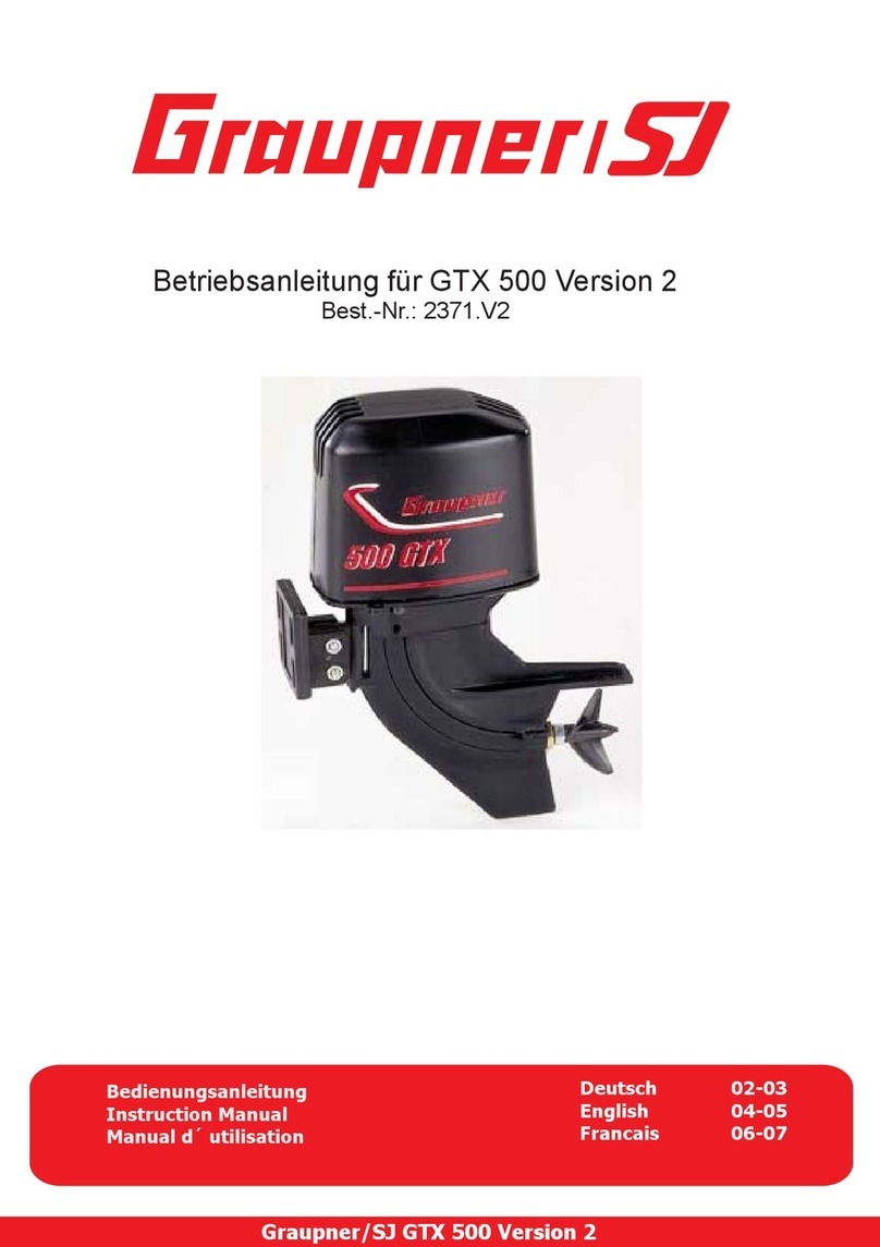
GRAUPNER GTX 500 Version 2 User manual

GRAUPNER GmbH & Co. KG D-73230 KIRCHHEIM/TECK GERMANY 06/2008
Änderungen vorbehalten! Keine Haftung für Druckfehler! # 44321
We reserve the right to introduce modifications. No liability for printing errors.
Sous réserve de modifications! Nous ne sommes pas responsables d'éventuelles erreurs d'impression!
Best.-Nr. 2371
2371.2
Bedienungsanleitung für den Außenbordmotor Graupner GTX-500
Der Außenbordmotor ist für kleine und mittelgroße Renn- und Sportboote bis ca. 60
cm Länge geeignet. Die verlustarme Kraftübertragung vom Motor zum Propeller
erfolgt über eine Ø 2,5mm V2A Flexwelle, die leicht zu warten ist. Die Best.-Nr. 2371
ist mit einem Elektromotor SPEED 500 7,2 V, Best.-Nr. 1799 ausgerüstet. Dieser ist
optimal geeignet für den Betrieb an Motoryachten mit mittlerer Geschwindigkeit. Die
Best.-Nr. 2371.2 wird ohne E-Motor geliefert. Passend dazu sind alle SPEED
Motoren der 500er Reihe. Diese Variante eignet sich besonders für Rennboote.
Wichtige Hinweise:
•Der Außenbordmotor darf erst nach einer fachgerechten Entstörung mit den
beiliegenden Entstörmitteln in Betrieb genommen werden. Hierzu muss die
Motorabdeckung abgenommen werden, diese nach oben anheben bis sie
ausrastet.
•Der Kondensator mit 470nF wird zwischen die beiden Anschlussfahnen
gelötet. Die Anschlusskabel polungsrichtig an den Motor löten und
anschließend so verlegen, dass sie durch die kleine rechtwinklige
Aussparung aus der Motorabdeckung geführt werden können.
•Der Außenbordmotor wird mit dem Motorträger, mit 2 bis 4 Schrauben (z.B.
mit Blechschrauben Ø 2,9 mm, Best.-Nr. 5877.10), am Heck des
Bootsrumpfes befestigt. Durch die Längsschlitze des Motorträgers ist eine
Höhenverstellung von ca. 10 mm zur Trimmung möglich. Der Neigungswinkel
des Außenbordmotors kann durch Lösen der M3 Zylinderkopfschrauben am
Motorträger eingestellt werden.
•Die Anlenkung des Außenborders erfolgt über die beiden seitlichen
Anlenkungslaschen und soll spielfrei erfolgen. Das Rudergestänge wird dazu
mittels je einem Gestängeanschluss, Best.-Nr. 1173, mit dem Außenborder
und dem Servoarm verbunden.
•Die Durchführungen im Schiffsrumpf für die Anschlusskabel sowie der
Ruderlenkung müssen sorgfältig mit Gummimanschetten gegen Wasser
abgedichtet werden.
•Seitlich am Außenborderschaft in der Nähe des Motorträgers befindet sich
eine kleine Bohrung durch die man die Klemmschraube der Flexwelle in der
Kupplung mit einem Inbusschlüssel 1,5 mm lösen kann. Zur Wartung der
Flexwelle dreht man die Wellenlagerung mit einem Schlüssel 8 mm aus dem
Schaft auf und zieht die Welle mit der eingeklebten Flexwelle heraus.
Achtung: Die Wellenlagerung hat Linksgewinde. Das heißt, man kann sie
herausnehmen, indem man mit dem Schlüssel im Uhrzeigersinn dreht.
•Evtl. muss die Flexwelle gekürzt werden, da Elektromotoren unterschiedlich
lange Antriebswellen besitzen. Die Flexwelle darf nicht zusammengedrückt
werden bei der Montage, da diese sonst stark am Gehäuse schleift. Dies kann
zur Zerstörung des Antriebs bzw. Motor durch Überlast führen.
•Den Außenbordmotor nicht ohne Belastung mit voller Betriebsspannung im
Leerlauf betreiben, da so evtl. durch zu hohe Drehzahl der Antrieb beschädigt
werden kann.

GRAUPNER GmbH & Co. KG D-73230 KIRCHHEIM/TECK GERMANY 06/2008
Änderungen vorbehalten! Keine Haftung für Druckfehler! # 44321
We reserve the right to introduce modifications. No liability for printing errors.
Sous réserve de modifications! Nous ne sommes pas responsables d'éventuelles erreurs d'impression!
•Die Kühlöffnungen am Gehäusedeckel nicht abdecken bzw. verkleben, sonst
kann der Motor überhitzen.
•Der Antrieb ist für den Betrieb mit halbgetauchter Schiffsschraube ausgelegt,
d.h. nur das jeweils untere Blatt der Schiffsschraube ist während der Fahrt im
Wasser eingetaucht.
•Der Antrieb ist nur für Vorwärtsfahrt gedacht. Bei Drehrichtungsumkehr des
Motors kann die Flexwelle beschädigt werden.
•Die Flexwelle und das Wellenlager sollten regelmäßig mit ausreichend
wasserneutralem Fett (z.B. Best.-Nr. 570) geschmiert werden. Dazu
demontiert man die Flexwelle wie oben beschrieben.
•Darauf achten, dass die laufende Schiffsschraube nicht mit irgendwelchen
Gegenständen oder Körperteilen in Berührung gerät.
•Den Betriebsspannungsbereich 6 – 9,6 Volt nicht überschreiten (bei Best.-Nr.
2371).
•Bei Überbelastung des Motors, d.h. bei mehr als 12 A Dauerlast, kann dieser
zerstört werden (bei Best.-Nr. 2371).
•Den Antrieb niemals im Salzwasser betreiben.
•Entfernen Sie nach jeder Fahrt das evtl. in den Antrieb eingedrungene
Wasser. Etwas Spritzwasser macht dem Motor nichts aus, der Motor muss nur
nach dem Betrieb getrocknet werden.
Ersatzteile:
Best.-Nr. Bezeichnung
2371.1 Flexwelle
1799 Elektromotor SPEED 500 7,2 V (nur bei Best.-Nr. 2371)

GRAUPNER GmbH & Co. KG D-73230 KIRCHHEIM/TECK GERMANY 06/2008
Änderungen vorbehalten! Keine Haftung für Druckfehler! # 44321
We reserve the right to introduce modifications. No liability for printing errors.
Sous réserve de modifications! Nous ne sommes pas responsables d'éventuelles erreurs d'impression!
Order No. 2371
2371.2
Operating instructions for the Graupner GTX-500 outboard motor
This outboard motor is designed for small to medium-sized racing and sports boats up to about 60 cm in length. Power
transmission from motor to propeller is via a 2.5 mm Ø V2A flexible shaft which is easy to maintain. The version Order No. 2371
is equipped as standard with a SPEED 500 7.2 V motor, Order No. 1799. This version is the ideal choice for powering motor
yachts at medium speed. The version Order No. 2371.2 is supplied without an electric motor, and can be fitted with any motor of
the 500 size. This version is a good choice for racing boats.
Important notes:
•The outboard motor must not be run in a model until the suppressor components have been fitted to provide adequate
interference suppression. First the motor cover must be removed; lever it upwards carefully until it disengages.
•Solder the 470 nF capacitor across the two motor terminals as a bridge. Solder the power cables to the motor taking
care to maintain correct polarity, and arrange them in such a way that they can be routed through the small
rectangular cut-out in the motor cover.
•Attach the outboard motor to the transom of the boat’s hull using two to four screws (e.g. 2.9 mm Ø self-tapping
screws, Order No. 5877.10). The slots in the motor mount allow height adjustment of about 10 mm for trimming. The
thrust angle of the outboard motor can be adjusted by loosening the M3 cheesehead screw on the motor mount.
•The steering movement of the outboard motor is controlled by the two lateral linkage lugs, and it is important that
there should be no slop in the linkage. We recommend that you connect the steering pushrod to the outboard motor
and the servo output arm using pushrod connectors, Order No. 1173.
•The openings in the hull for the power cables and rudder linkage must be carefully sealed with rubber grommets or
bellows to prevent water penetrating the hull.
•At the side of the outboard motor shaft, close to the motor mount, you will find a small hole through which you can
access the flexi-shaft clamping screw using a 1.5 mm allen key. The clamping screw must always be tightened very
firmly, otherwise the flexi-shaft might slip inside the coupling. If you wish to remove the flexi-shaft, unscrew the shaft
bearing from the shaft using an 8 mm A/F spanner, and withdraw the shaft and the flexi-shaft which is glued into it.
Caution: the shaft bearing has a left-hand thread. This means that you have to turn the spanner clockwise in order
to undo and remove it.
•Do not run the outboard motor on its full operating voltage under no-load conditions (i.e. out of water), as this would
allow the system to spin up to excessive speed which could damage the flexi-shaft.
•Do not cover or otherwise seal the cooling holes in the housing cover, as this would cause the motor to overheat.
•The outboard motor is designed for use with a surface-piercing propeller, i.e. only the lower propeller blade is
submerged at any one time when the boat is running.
•The motor system is designed for forward running only. Running the motor in reverse may damage the flexi-shaft.
•The flexi-shaft and the shaft bearing should be lubricated occasionally using non-contaminating grease (e.g. Order
No. 570). Access to these parts is possible by removing the flexi-shaft as described above.
•Ensure that the propeller does not contact any objects or parts of your body when the motor is running.
•The operating voltage range is 6 - 9.6 Volts (applies to Order No. 2371); do not exceed the stated voltage.
•Take care not to overload the motor, i.e. more than 12 A continuous current, as this may wreck the motor (applies to
Order No. 2371).
•Never run the outboard motor in salt water
•After every run remove any water which manages to get inside the case. A few drops of water will not damage the
motor, but it should be dried out after use.
Replacement parts:
Order No. Description
2371.1 Flexi-shaft
1799 SPEED 500 7.2 V electric motor (Order No. 2371 only)

GRAUPNER GmbH & Co. KG D-73230 KIRCHHEIM/TECK GERMANY 06/2008
Änderungen vorbehalten! Keine Haftung für Druckfehler! # 44321
We reserve the right to introduce modifications. No liability for printing errors.
Sous réserve de modifications! Nous ne sommes pas responsables d'éventuelles erreurs d'impression!
Réf. N° 2371
2371.2
Instructions d'utilisation pour le moteur Hors-bord Graupner GTX-500
Ce moteur hors-bord est conçu pour l'équipement des bateaux de course et de sport de tailles petite et moyenne. La
transmission de la puissance du moteur à l'hélice se fait par un arbre flexible V2A de φ 2,5mm d'un entretien facile. La Réf.
N°2371 est équipée d'un moteur électrique SPEED 500 7,2 V.,, Réf. N°1799. Cette version est idéalement adaptée pour la
propulsion des Yachts à moteur à vitesse moyenne. La Réf. N°2371.12 est livrée sans moteur électrique. Elle est adaptée pour
tous les moteurs SPEED des séries 500. Cette version convient particulièrement pour la propulsion des bateaux de course.
Conseils importants:
•Le moteur hors-bord ne devra être mis en service qu'après avoir été correctement antiparasité avec le condensateur
fourni. Pour cela, le capot du moteur devra être retiré en le tirant vers le haut jusqu'à ce qu'il se décrante.
•Souder le condensateur de 470 nF entre les deux bornes avec en même temps les fils de raccordement au moteur en
respectant les polarités et en les disposant de façon à ce qu'ils puissent sortir par la petite ouverture rectangulaire
dans le capot du moteur.
•Le moteur hors-bord sera fixé par son support sur la poupe du modèle avec 2 à 4 vis (Par ex. avec des vis parker
φ 2,9mm, Réf. N°5877.10). Grâce aux boutonnières percées dans le support du moteur, un déplacement en hauteur
d'environ 10mm pour le réglage est possible. L'angle d'inclinaison du moteur hors-bord pourra aussi être réglé en
desserrant les vis à tête cylindrique M3 sur le support du moteur.
•La commande d'orientation du moteur hors-bord se fait par les deux pattes latérales et doit être exempte de jeu. Pour
cela, les tringleries de commande reliant le moteur hors bord au palonnier du servo seront connectées avec des
raccords de tringlerie, Réf. N°1173.
•Les passages pour les fils de raccordement au moteur et pour les tringleries devront être soigneusement étanchéifiés
contre les infiltrations d'eau avec des passe-fils ou des soufflets en caoutchouc. Un petit trou situé latéralement dans
le carter, à proximité du support du moteur, permet de desserrer la vis qui bloque l'arbre flexible dans l'accouplement
avec une clé Allen de 1,5mm. Pour l'entretien de l'arbre flexible, il faut desserrer son palier avec une clé de 8mm
pour pouvoir le sortir du carter. Attention: Le filetage du palier est à Pas à gauche; ce qui signifie que pour le retirer du
carter, il faut tourner la clé dans le sens horaire.
•Ne jamais faire tourner le moteur hors-bord à vide, sans charge, sous la pleine tension d'alimentation, car la
propulsion pourrait être détériorée par l'atteinte d'un trop haut régime.
•Les ouies d'aération percées dans le capot ne devront pas être obturées, car autrement le moteur surchauffera.
•La propulsion est conçue pour un fonctionnement une l'hélice à demi-immergée, c'est-à-dire qu'à chaque tour une
seule pale de l'hélice trempe dans l'eau.
•La propulsion est conçue uniquement pour la marche avant; une inversion du sens de rotation du moteur pourrait
détériorer l'arbre flexible.
•L'arbre flexible et son palier devront être régulièrement lubrifiés avec une graisse spéciale (Par ex. Réf. N°570); pour
cela, l'arbre sera démonté comme il a été décrit plus haut.
•Veiller toujours à ce qu'aucun objet quelconque ou une partie du corps ne viennent pas en contact avec l'hélice en
rotation.
•Ne pas dépasser la plage de tensions d'alimentation de 6à 9,6 Volts (avec la Réf. N°2371).
•Ne pas surcharger le moteur à plus de 12 A, sous peine de le détériorer (avec la Réf. N°2371).
•Ne jamais faire fonctionner la propulsion dans de l'eau salée.
•Evacuer l'eau éventuellement infiltrée dans la propulsion après chaque séance de navigation. Quelques projections
d'eau ne détérioreront pas le moteur qui devra seulement être séché après le fonctionnement.
Pièces détachées:
Réf. N° Désignation
2371.1 Arbre flexible
1799 Moteur électrique SPEED 500 7,2 V (seulement pour la Réf. N°2371)
Other manuals for GTX 500 Version 2
1
Table of contents
Languages:
Other GRAUPNER Outboard Motor manuals