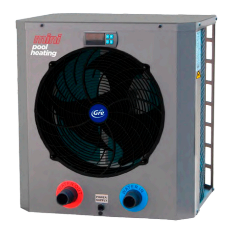
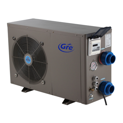
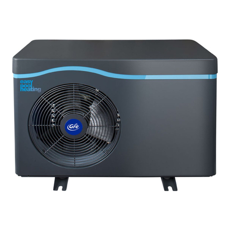
GRE BC3800 User manual

BOMBA CALOR
MODELS Bomba calor 3,8 KW Bomba calor 4,5 KWBomba calor 9 KW Bomba calor 12,5 KW Bomba calor 21 KW
CODES BC3800 BC4500 BC9000 BC13000 BC21000
HEATPUMP
InstructionManual
POMPEÀCHALEUR
Manueld´instructions
BOMBADECALORPARAPISCINA
Manual deInstrucciones
WÄRMEPUMPE
Bedienungsanleitung
POMPADICALORE
Manualedelle instruzioni
BOMBADECALOR
Manual deinstruções
WARMTEPOMP
Handleiding met instructies
WE RESERVE THE RIGHT TO CHANGE ALL OR PART OF THE FEATURES OF THE ARTICLES OR CONTENTS THIS DOCUMENT
WITHOUT NOTICE.Nos reservamos el derecho de cambiar total o parcialmente las características de nuestros artículos o contenido de
este documento sin previo aviso.
Nous nous réservons le droit de modifier totalement oru en partie les caracteristiques de nos articles ou le contenu de ce document san
pré avis.
Wir behalten uns das recht vor die eigenschaften unserer produkte oder den inhalt diese prospektes teilweise oder wollstanding, ohne vorherige benachichtigung
suandern.
Ci riservamo il diritto di cambiare totalemente o parzialmente le caratteristiche tecniche dei nostri prodotti ed il contenuto di questo documento senza nessum
preavviso.
Wij behouden ons het recht voor geheel of gedeeltelijk de kenmerken van onze artikelen of de inhouk van deze handleiding zonder voorafgaand bericht te wijzigen.
Reservamo-nos no dereito de alterar, total ou parcialmente as caracteristicas os nossos artigos ou o conteúdo deste documento sem aviso
prévio.
V.20
15
-
12
-
01 R410A www.gre.es
- 1 -

- 2 -

DESCRIPTION OF THE HEAT PUMP
This heat pump is used to heat water from a pool or spa and thus extend bathing season.
A. Technical characteristics
- The calculation of power has been done with an outdoor air temperature of 15℃, a water
temperature of 26℃and 70% humidity.
- Operational temperature limits:
Outdoor minimum air temperature: 5℃
Maximum temperature of pool water: 40℃
Maximum inlet water pressure 3 bar.
Warning:
- Do not place your hand or any other objects into the air outlet and fan. It could damage
the heat pump and cause injuries;
- In case of any abnormality with the heat pump, cut off the power immediately and
contact a professional technician;
It is strongly advised to place a protective guard around the unit to keep children away from the heat
pump.
An authorized electrician must connect the Heat Pump to the power. (230V 1ph or 380V-400V 3ph)
FIGURE 1 – POWER CONNECTION
FIGURE 2 – MINIMUM DISTANCE REQUIREMENTS
1. First-time start-up
Note: in order for the unit to heat the pool (or spa), the filter pump must be running so that
the water can circulate through the heat pump. Without this circulation, the heat pump will
not start.
When all connections have been made and checked, the following steps should be followed:
1). Turn on the filter pump. Check for leaks.
2). Turn on the electrical power supply to the unit, then press the ON/OFF key on the electronic
control panel.
3). When the unit has been running for a couple of minutes, check if the air leaving the unit is
cooler than the ambient temp.
4). Check the performance of the flow switch as follows: with the unit running turn the filter pump
off. The unit should also switch off automatically.
5). The unit and the filter pump should run 24 hours a day until the desired pool water
temperature has been reached. Once the set temperature is reached, the unit will switch itself off.
As long as the filter pump is running, the unit will restart automatically when the temperature of
the pool water drops more than 1°C below the set temperature.
- 3 -

2. Controller diagram
A. : Switch heat pump on or off
B. MODE: Select auto, heating or cooling mode.
Corresponding indicator light will go on when selected
C. ▲or ▼: Press to change digits.
D. : ‘Timer start’ setting button
E. : ‘Timer stop’ setting button
F. : Time setting button
3.How to start heat pump
When connected with power, the controller will display the time. This means that the unit is in
standby. Press to start the heat pump. The display will show the inlet water temperature.
4. How to change mode
Press MODE to select auto, heating or cooling mode: the indicator light on the right side of the
controller will indicate the mode selected.
5.How to set the desired water temperature
1).The unit has a unique temperature controlling system to satisfy any requirement.
Heating Only Mode : (+ 1/ - 1°C ‘‘ from set point ’’ )
In Heating Mode the heat pump will only heat.
It will heat up to 1°C higher than the "Set" Temp. The heat pump will then stop, but it will
continue to monitor the temperature in your pool.
(The filter pump must be running to enable the heat pump to measure the temperature).
- 4 -

When the temperature in the pool is 1°C lower than the "Set" Temp., the heat pump will start
again.
Cooling Only Mode : (+ 2/ - 0°C ‘‘ from set point ’’ )
This works the same way, but will only cool when the temperature exceeds the cooling
"Set" Temp. by 2°C and it will cool down to the "Set" Temp.
Remember that the highest Cooling "Set" Temperature is 37°C.
Auto Mode : (‘‘Automatically Heating Mode or Cooling Mode’’ )
In Auto Mode your heat pump will try to keep your desired pool temperature at all times.
Example :
If you want your pool to be 30°C:
a. If the pool-water is below 29°C the heat pump will start heating.
b. When the temperature reaches 31°C the heat pump will stop.
c. If the temperature in your pool continues to rise, and passes 32°C, the heat pump will
start again, BUT in Cooling Mode, and cool down to 30°C.
d. If now the temperature continues to drop, and it drops below 29°C, the heat pump will
start again, BUT in Heating Mode.
In Auto Mode the heat pump will try to keep the temperature within 2°C higher and 1°C
lower that your "Set" Point.
(Remember that the filter pump has to run in order for the heat pump to work)
2).How to set using the display controller :
a. First select the desired mode: auto, heating or cooling
b. Regardless if the heat pump is "running" or in "standby" press ▲or ▼.
The display will show the currently set water temperature of the selected mode with a flashing number:
While it is blinking you can change the water temperature by pressing ▲or ▼to the temperature you
want.
(Before you select the desired temperature, make sure you are in the correct mode: Heating / Cooling /
Auto.)
After you see the desired temperature blinking, wait 5 sec. and the temperature is stored.
Cooling Mode
Heating Mode
Auto Mode
Range 8 - 28℃
Range 15 - 40℃
Range 8 - 40℃
6. How to check parameter settings and measured values of current status
Regardless whether the heat pump is "running" or in "standby" press MODE for 5 sec.
The display will start to blink (both digits)
- 5 -

The first digit indicates the "parameter"
The second digit(s) indicate the value of the "parameter"
This "reading mode" will be deactivated if you do not press a button for 10 sec.
By pressing ▲or ▼you will see parameters from 0 to F (one by one)
Make a note of each parameter (for your records.)
Wait 10 sec. and this function is deactivated (you are back to normal)
7. How to set the clock
1. In standby, press : hour digits will flash to indicate that they can be modified by pressing
▲or ▼
2. Press again: minute digits will flash to indicate that they can be modified by pressing ▲
or ▼
3. Press again for final confirmation of time setting
Once time has been set, LED display will show time when heat pump is on standby.
8. How to set timer start and timer stop
a) Press to activate ‘timer start’ setting: hour and minute digits will be flashing together.
b) Press again to modify the hour setting: the hour digits will flash meaning they are ready
to be modified by pressing ▲or ▼.
c) Press again to modify the minute setting: the minute digits will flash meaning they are
ready to be modified by pressing ▲or ▼.
d) Press to confirm setting - display will return to standby status. ‘Timer start’ green
indicator light will light up to show the starting time has been set.
e) Repeat the same procedure using instead of to set ‘timer stop’. ‘Timer stop’ red
indicator light will light up to show the stopping time has been set.
- 6 -

Note: ‘timer start’ and ‘timer stop’ can be set together or separately (i.e. it is possible to set ‘timer
start’ only and then stop the unit manually or set ‘timer stop’ only and start the unit manually).
Timer start
indicator
Timer stop
indicator
9. How to cancel ‘timer start’ and ‘timer stop
Press to activate ‘timer start’ or to activate ‘timer stop’: the corresponding indicator light will
be flashing. Press to cancel ‘timer start’ or ‘timer stop’.
INFO:
The parameter can be changed by a skilled person. A code is needed to do so.
The procedure for this is in the "Main Manual".
The keypad can be locked to prevent unauthorized use or changes of the heat pump.
The procedure for this is in the "Main Manual".
If the control panel is locked, your dealer can advise you how to unlock it.
10. Recommendations
Important: failure to comply with these recommendations will invalidate the warranty
Note: non-compliance with one or more of these recommendations can damage the heat
pump beyond repair. Always install water-treatment equipment (e.g. chemical dosing
systems) after the water outlet of the heat pump, especially if the chemicals are automatically
added to the water (e.g. automatic chemical dosing systems).
A check valve should also be installed between the outlet of the heat pump and the water-
treatment equipment to prevent products from flowing back into the heat pump if the filter
pump stops.
11. Heat pump winterizing
Important: failure to take necessary precautions for winterising can damage the heat pump,
which will invalidate the warranty.
The heat pump, filter pump, filter and conduits must be protected in areas where the temperature
can drop below freezing point. Evacuate all water from the heat pumps as follows:
1. Disconnect the electrical power supply to the heat pump.
2. Close the water supply to the heat pump completely.
3. Disconnect water inlet and outlet coupling fittings of the heat pump and let the water drain out
of the unit. Make sure all water is out of the heat pump. (if necessary, tilt the heat pump
until all water has been drained from the heat exchanger). Damage caused to the heat
exchanger due to freezing will not be covered by the warranty.
4. Loosely re-attach water inlet and outlet coupling fittings of the heat pump in order to prevent
dirt from getting into the conduits.
- 7 -

12. Restarting the pump after winter
If you emptied the heat pump for winterising, follow the steps below to restart it in spring:
1. First check that there is no dirt in the conduits and that there are no structural problems.
2. Check that the water inlet and outlet fittings are adequately fastened. Check that ''water inlet''
and ''water outlet'' are correct according to the labels on the heat pump (water out from the
filter unit = water inlet on heat pump)
3. Start the filter pump to start the water flow to the heat pump. Adjust the by-pass so there is
enough water running through the heat pump. Normally on a small filter system the by-pass
can be closed, so all circulated water goes through the heat pump.
4. Reconnect the electrical power supply to the heat pump and turn the heat pump ON.
13. Check-up
Our heat pumps have been built and developed to last long if they have been installed correctly and
can operate in normal conditions. Regular check-ups are important if you want your heat pump to
function efficiently for many years. Below are some recommendations to ensure optimal working
conditions for your heat pump.
1). Make sure that the service panel is easily accessible.
2). Keep the area surrounding the heat pump free of organic waste.
3). Prune any vegetation around the heat pump so that there is sufficient free space around the
pump.
4). Remove any water sprinklers that are near the heat pump as they could cause damage to it.
5). Prevent rain from running directly onto the heat pump from a roof. Install proper drainage.
6). Do not use the heat pump if it has been flooded. Immediately contact a qualified technician to
inspect the heat pump and carry out necessary repair.
Condensation can occur when the heat pump is running. This condensation water can flow away
through an opening in the base pan of the unit. The amount of condensation water will increase
when humidity is high. Remove any dirt that could block the water outlet on the bottom pan. 5 to 20
liters per day of condensation water can be produced while the unit is running. If more condensation
is produced, stop the heat pump and wait for one hour before checking for water leakage (keep the
filter pump running).
Note: a quick way to verify that the water running is because of the condensation. Shut off
the unit and keep the pool pump running. If the water stops running out, it is condensation.
AN EVEN QUICKER WAY IS TO TEST THE DRAIN WATER FOR CHLORINE. If no chlorine is
detected, the drain water is a result of condensation.
Also make sure that the air in and out passages are free, and prevent air out from immediately re-
entering to the air in. (It is important to have min. 2.5m free space at the air out side of the heat
pump).
- 8 -

14. FIGURE 3 –Maintenance and Inspection
15. Troubleshooting guide
Incorrect installation may result in an electrical charge that could lead to death or serious injury of
users, installers or others by electrical shock and it may also cause damage to heat pump.
DO NOT attempt to modify the internal configuration of the heat pump.
1. Keep your hands and hair clear of the fan blades to avoid injury.
2. If you are not familiar with your pool filtration system and heat pump:
a. Do not attempt to carry out any adjustment or service without consulting your dealer,
pool professional or air conditioning contractor.
b. Read the entire installation manual before attempting to use, service or make
adjustments to the unit.
c. Wait for 24hours after the installation before starting the heat pump to prevent
damage to the compressor. (If the heat pump has been transported and carried all the
time with the feet down, it can be started immediately).
Note: Switch off the power before carrying out any maintenance or repairs.
IMPORTANT REMARK: if a malfunction cannot be resolved immediately, in order to analyse the
problem we will need to know the message (error code) that is showing on the display controller as
well as the values for the settings (parameters 0-A). We also need to know the status of the heat
pump: the ambient temperature, water inlet / outlet temperature, if there is cold air coming out from
the heat pump, if the grill (evaporator) is cold, or if there is ice on the heat pump.
Please keep this information at hand when calling customer service (describe the issue).
On the following pages you will find an overview of the different types of failure problems that can
occur together with instructions on how to solve them.
- 9 -

16. Overview of failure code on Display (LED controller)
Wire
controller Protection/Failure Check Solution
PP01/PP1
Inlet water temp. sensor
failure
1.
Check the connection of inlet
water sensor.
2.
Check if the sensor is broken.
1.
Reconnect the sensor.
2.
Replace the sensor.
PP02/PP2
Outlet water temp. sensor
failure
1.
Check the connection of outlet
water sensor.
2.
Check if the sensor is broken.
1.
Reconnect the sensor.
2.
Replace the sensor.
PP03/PP3
Coil 1 temp. sensor failure
1.
Check the connection of coil 1
temperaturesensor.
2.
Check if the sensor is broken.
1.
Reconnect the sensor.
2.
Replace the sensor.
PP04/PP4
Coil 2 temp. sensor failure
1.
Check the connection of coil 2
temperature sensor. temperature
2.
Check if the sensor is broken.
1. Reconnect the sensor. 2.
Replace the sensor.
PP05/PP5
Ambient temp. sensor failure
1.
Check the connection of ambient
temperaturesensor.
2.
Check if the sensor is broken.
1.
Reconnect the sensor.
2.
Replace the sensor.
PP06/PP6
Protection for excessive
temp. difference between
water inlet & outlet
1.
Check if there is any blockage in the
water circuit.
2.
Check if the water flow volume is
enough.
3.
Check if the water pump is working.
1.
Remove the cause of the
blockage.
2.
Increase the water flow
volume.
3.
Repair or replace the water
pump.
PP07/PP7
Anti-freeze protection for
cooling
Refer to PP06. Refer to PP06.
PP07/PP7
Winter anti-freeze protection
Ⅰ
No action required
PP07/PP7
Winter anti-freeze protection
Ⅱ
No action required
EE03/EE3
Water flow switch failure
1.
Check water flow.
2.
Check if water pump is working.
3.
Check if flow switch is broken.
4.
Check if wiring diagram connection
of flow switch is correct.
1.
Increase water flow.
2.
Repair or replace water pump.
3.
Replace flow switch.
4.
Reconnect the wiring.
EE01/EE1
EE06/EE6
High or Low pressure
protection
1.
Check if lack refrigerant is too low
(for low pressure).
2.
Ambient temp. or water inlet temp.
is too low (for low pressure).
3.
Check if there is a blockage in water
circuit or if water flow is not enough
(for high pressure)
4.
Check if high or low pressure switch
is broken.
5.
Check if there is a blockage in
refrigerant circuit (for high pressure).
1.
Fill up with enough
refrigerant.
2.
Check by reducing water flow.
3.
Remove cause of blockage or
increase water flow.
4.
Test by shorting the high
pressure switch or low pressure
switch. Must be changed by
refrigeranttechnician.
5.
Must be checked and repaired
by refrigerant technician.
EE05/EE5
Failure of excessive temp.
difference protection between
water inlet & outlet
1.
Check if there is enough water flow
volume.
2.
Check if inlet / outlet water temp.
sensor is working.
1.
Increase water flow.
2.
Replacesensor.
EE08/EE8
Communicationfailure
Check the connection
Change PCB and / or Display
- 10 -

17. FIGURE 4 –EXPLODED VIEW
18.PRODUCT RECYCLING
This unit has a refrigeration gas in liquid state and electrical components. When the heat pump
reaches the end of its service life, it should be dismantled by an authorised company or it
should be sent to the place selected by the local authorities.
With the aim of reducing the amount of electrical and electronic equipment
residues and the danger of their components, to promote the recycling of the
equipment and the appreciation of their residues, and to determine a suitable
management that attempts to improve the effectiveness of the environmental
protection, a series of regulations applicable to the manufacturing of the
product and others related to the correct environmental management when
they become residues have been implemented.
It is also envisaged to improve the environmental behaviour of all the agents involved in the
service life of the electrical and electronic equipment, such as the producers, distributors,
users, and, specially, those agents directly involved in the management of the residues
derived from this equipment.
As of 13 August 2005, when you wish to throw away this unit, you have two possible return
systems:
•
If you acquire a new one that is of an equivalent type or it has the same functions as the
one thrown away, you could hand it over at no cost to the distributor.
•
Or you could take it to the place so selected by the local authorities.
The units are labelled with the symbol of a “crossed out wheeled rubbish container “. This
symbol denotes the need for its selective and differentiated collection from the rest of urban
rubbish. Possible effects over the environment or human health of the dangerous materials it
may contain.
PVC
The most used plastifying agent in the different PVC applications is the DEHP (di-2-ethyl
hexyl phthalate). The tests conducted in different laboratories demonstrate that it does not
present risks for human health in the concentration levels so used in finished articles, according
to the information from the German BUA (Advisory Body for the Relevant Environment of the
Existing Substances) and the VGA (German Health Authority) among others. The results of
these tests, together with the data collected in biodegradation studies, confirm that the DEHP
cannot be considered dangerous for the environment. All additives used in the PVC
formulations and therefore in the food industry applications are perfectly regulated at both
European and Spanish level.
In Europe, the EC Directive 90/128/EU, later modified by the 95/3/EU. In Spain, we should methe
Royal Decrees 1125/1982 of 30 April 1982, later confirmed by the 1042/1997 of 27 June 1982. The
service life analyses (SLA) demonstrate that the environmental impact of the PVC is equivalent or
even more favourable than those corresponding to other materials.
- 11 -

Something wrong?
If you suspect something is wrong with your Bomba calor Heat Pump ?
Before you call for service read trough Chapter C. Potential Failures, and fill out this form.
If possible send by Email to your dealer, and keep it in front of you when you call the serviceman.
Type of Heat Pump: Bomba calor 3.8 KW , Bomba calor 4.5 KW , Bomba calor 9 KW ,
Bomba calor 12.5 KW , Bomba calor 21 KW .
1. Serial No:
2. Installation date: Year Month (Date )
3. Sold by: Installed by:
4. Heat Pump installed: (a) Outside (b) Inside (c) Inside in a shed with open door
5. Distance to obstacles: Front m Back m
6. Pool Surface Area: m2
7. Filter Pump: kW.
8. Pressure on the manometer on Filter-tank:
9. Air temperature C.
10. Gas Pressure on manometer on heat pump? running not running
11. Max Pool Temperature reached °C
12. Desired Pool Temp °C.
13. Does the pool have a cover? YES / NO
14. Is there Ground Water around the pool? YES / NO / I DON’T KNOW
15. Try to describe the problem:
A. If Heat Pump is running continuously:
1. Is the heat pump: (a) Heating (b) Not Heating enough (c) Not heating at all
2. Is there an Error Code? YES / NO // If YES, what is the Error Code?
(check the error code according to p.10 in the manual)
3. Is the fan running? YES / NO
4. Is there ice on “Radiator” (Evaporator) ? YES / NO
5. Is there Cold Air from Radiator? YES / NO
6. Are there leaves, fungus or dirt on or between the fins on the “Radiator” (Evaporator)? YES / NO
7. Stop the Heat Pump . Wait 3 min. Start Heat Pump . Listen and watch the Display for 3 min.
8. Does the fan start? YES / NO
9. After approx 1 min, does the compressor start? YES / NO
10. Voltage on the heat pump connections: Standby V Running V
- 12 -

B. If Heat Pump is not running or only running for short time.
1. What is the voltage at the Heat Pump connections (heat pump not running) V.
2. Voltage at the Heat Pump connections when you are trying to start the Heat Pump? V.
3. What is the Display showing when you are trying to start / run the heat pump?
4. Stop the Heat Pump
5. Display is: BLANK / SHOWING THE TIME / SHOWING A NUMBER .
6. Wait 3 min. Start Heat Pump . Listen and watch the Display for 3 min.
7. Display is: BLANK / SHOWING THE TIME / SHOWING A
NUMBER.
8. Can you hear the Heat Pump is trying to start? YES / NO
9. Is there an Error Code? YES / NO. If Yes, Error Code
10. Is the Fan starting? YES / NO
11. Can you hear the Compressor is trying to start? YES / NO.
12. Does the Compressor start for a short time only? YES / NO
13. Is there an Error Code? YES / NO If Yes, Error Code
14. Try to describe the problem:_
C. Potential Failures.
a. Error EE3. Low or no water-flow. Bypass wrongly set. Filter Clogged. Air in the filter
system.
b.Ice on the “radiator” (Evaporator). Wrong parameter settings. Too low air temperature PCB
defect.
c.Too little heating. Energy loss from pool too big. Obstacles in front of the
heat pump.Heat Pump installed inside a shed.
Recirculation of air trough the heat pump. “Radiator” filled
with leaves and dirt
d.The heat pump stops. Error EE3. Water flow to low, Change Water flow Switch.
e.The heat pumps stops and starts frequently Air in the filter system. Air leakage in pipes on suction
side Flow switch..
f.Display showing 8888 Display defect PCB defect by Lightning or Power shock.
g.Heatpumpdoesnotworkperiodically Weak power Supply. Too long Supply Cable. Too
small mm2 in cable.
h.Problem to start the compressor. Starting / running Capacitor defect.
- 13 -

D. Register info.
Unit
Reference No. Model
INSTALLER
Name Town
Address
Telephone Start-update
USER
Name Town
Address
Telephone Start-update
(To be filled by the installer) INSTALLER’S STAMP
For all units,the warranty will only have effect if this card is duly completed
E. Service calls.
1. Date . □Annual service □Problem
2. Date . □Annual service □Problem
3. Date . □Annual service □Problem
Copy and send page 24, 25 & 26 on beforehand for service, checking or repair.
- 14 -

GUARANTEES
There is a 2-year warranty for all the parts.
In the event of warranty cancellation:
A failure or a mistake in the hibernation procedure leads to the cancellation of the
warranty. The elimination, suppression or modification of one of the safety components
involves the cancellation of the warranty.
A failure in the installation procedure which is related to the lack of observance of the
instructions contained in this manual will mean the cancellation of the warranty.
1. WARRANTY COVERAGE
1.1 In accordance with these provisions, the salesman guarantees that the product
corresponding
to this warranty (“the product”) does not present any non-conformance at the moment of its
delivery.
1.2 The warranty period of the product is of two (2) years and it will take effect as of the time of
delivery to the buyer.
1.3 If a Product non-conformance occurs and the buyer nGotifies it to the salesman during the
Warranty Period, the salesman should repair or replace the Product at his own cost in the
appropriate place, unless it is impossible or disproportionate.
1.4 When the Product cannot be repaired nor be replaced, the buyer shall be able to ask for a
proportional price reduction or, if the non-conformance is sufficiently important, the discharge of
the sales contract.
1.5 The replaced or repaired parts by virtue of this warranty will not extend the warranty term of
the original Product, although they will have its own warranty.
1.6 For the effectiveness of this warranty, the buyer will have to credit the acquisition date and
delivery date of the Product.
1.7 When the delivery of the Product to the buyer had been more than six months before and the
buyer alleges non-conformance with the Product, the buyer will have to prove the origin and
existence of the alleged fault.
1.8 The present Warranty Certificate does not limit or prejudges the rights the consumers are
entitled by virtue of local prevailing and applicable regulations.
2. CONDITIONS TO WARRANTY
The warranty will
and signed by all
only have
effect if
the coupon is returned duly completed, sealed
interested
parties
2.1 This warranty covers the products referred to in this manual.
2.2 For the effectiveness of this warranty, the buyer will have to strictly follow the manufacturer
instructions included in the documentation enclosed with the Product, whenever this warranty is
applicable according to the Product range and model.
2.3 When a calendar for the substitution, maintenance or cleaning of certain parts or components
of the Product is specified, the Warranty will only be valid when the calendar has been observed.
3. LIMITATION TO LIABILITY
3.1 This warranty will be solely applicable to those sales to consumers, being understood
“consumers” as those people who acquire the Product with a purpose that does not fall within
the
scope of their professional activity.
3.2 No warranty is granted referred to the wear and tear caused by the use of the Product. In
relation to the parts, components and/or consumable materials such as batteries, light bulbs etc.,
it will refer to the provisions of the documentation enclosed with the Product, when applicable.
3.3 The warranty does not cover those cases where the Product: (I) has been incorrectly treated;
(II) has been repaired, maintained or manipulated by a non-authorized person, or (III) has been
repaired or maintained with non-original pieces.
3.4 When the non-conformance of the Product is a consequence of an incorrect installation or
start-up, this warranty will only cover those installations or start-ups included in the contract of
sale of the Product and carried out by the salesman or under his/her responsibility.
- 15 -

- 16 -

DESCRIPCIÓN DE LA BOMBA DE CALOR
Esta bomba de calor se usa para calentar el agua de la piscina o del spa, y así alargar la
temporada de baño.
A.
Característicastécnicas
-
El cálculo de potencia se ha realizado con una temperatura exterior de 15℃, una
temperatura del agua de 26℃y un 70 % de humedad.
-
Límites de temperatura operativa:
-
Temperatura mínima exterior: 5℃
-
Temperatura máxima del agua de la piscina: 40℃
-
Presión máxima de agua entrante: 3 bares.
Advertencia:
-
No coloque la mano ni otros objetos en la salida de aire ni en el ventilador. Podría dañarse la
bomba de calor y provocar lesiones.
-
En caso de que la bomba de calor no funcione correctamente, desconéctela de la corriente
inmediatamente y póngase en contacto con un técnico profesional.
Se aconseja encarecidamente colocar una cubierta de protección alrededor de la unidad para
mantener a los niños alejados del aparato.
Debe ser un técnico autorizado quien conecte la bomba de calor a la corriente (230V 1ph o 380V-
400V 3ph).
F1
F2
1.
Primera puesta en marcha
Nota: con el fin de que la unidad caliente la piscina (o el spa), la bomba de filtración debe
estar en marcha para que el agua pueda circular a través de la bomba de calor. Sin esta
circulación, la bomba de calor no arrancará.
Cuando haya efectuado y comprobado todas las conexiones, siga los pasos siguientes:
1). Conecte la bomba de filtración. Compruebe si hay fugas.
2). Conecte la unidad al suministro eléctrico, a continuación, pulse la tecla ON/OFF del panel
de control electrónico.
3). Cuando la unidad haya estado funcionando durante un par de minutos, compruebe si el
aire que sale de la unidad es más frío que la temperatura ambiente.
4). Compruebe el rendimiento del conmutador de flujo de la siguiente manera: con la unidad
en marcha, apague la bomba de filtración. La unidad también debería apagarse
automáticamente.
5). La unidad y la bomba de filtración deberían estar en marcha durante todo un día (24 horas
seguidas) hasta que se alcance la temperatura deseada en el agua de la piscina. Una vez
alcanzada la temperatura deseada, la unidad se apagará automáticamente. Mientras la
bomba de filtración esté en marcha, la unidad se reiniciará automáticamente cuando la
temperatura del agua de la piscina baje más de 1°C por debajo de la temperatura deseada.
2.
Diagrama de control
A. : encienda o apague la bomba de calor.
B. MODO: seleccione modo automático, calefacción o
refrigeración. Se encenderá el correspondiente indicador
luminoso.
C. ▲o ▼: pulse para cambiar los dígitos.
- 17 -

D. : botón de configuración de “Inicio del temporizador”.
E. : botón de configuración de “Detención del temporizador”.
F. : botón de configuración de hora.
3.
Cómo poner en marcha la bomba de calor
Cuando esté conectada a la corriente, el panel de control mostrará la hora. Esto significa que la unidad
está en espera (standby). Pulse para poner en marcha la bomba de calor. La pantalla mostrará la
temperatura del agua que entra.
En espera En marcha
4.
Cómo cambiar el modo
Pulse MODO para seleccionar modo automático, calefacción o refrigeración: el indicador
luminoso de la parte derecha del panel de control mostrará el modo seleccionado.
Modo automático Modo calefacción Modo refrigeración
5.
Cómo configurar la temperatura deseada del agua
1). La unidad tiene un exclusivo sistema de control de temperatura para satisfacer todas las
necesidades.
Modo solo calefacción: (+ 1/ - 1°C “del punto establecido”)
En el modo calefacción la bomba de calor solo calentará.
Calentará 1°C más la temperatura “establecida”. La bomba de calor se detendrá, pero continuará
realizando un seguimiento de la temperatura de su piscina.
(La bomba de filtración debe estar en marcha para permitir a la bomba de calor medir la temperatura).
Cuando la temperatura de la piscina sea 1°C inferior a la temperatura “establecida”, la bomba de
calor se pondrá de nuevo en marcha.
Modo solo refrigeración: (+ 2/ - 0°C “del punto establecido”)
Esto funciona de la misma manera, pero solo enfriará cuando la temperatura supere la temperatura
de refrigeración “establecida” en 2°C y enfriará hasta la temperatura “establecida”.
Recuerde que la máxima temperatura de refrigeración “establecida” es 37°C.
- 18 -

Modo automático: (“Modo automático de calefacción o refrigeración”)
En el modo automático, su bomba de calor intentará mantener la temperatura deseada de la piscina
en todo momento.
Ejemplo:
Supongamos que quiere que su piscina esté a 30°C:
a.
Si la temperatura del agua de la piscina es inferior a 29°C, la bomba de calor comenzará a
calentar el agua.
b.
Si la temperatura alcanza 31°C, la bomba de calor se detendrá.
c.
Si la temperatura de su piscina continúa aumentando y sobrepasa los 32°C, la bomba de
calor se pondrá en marcha de nuevo, PERO en Modo refrigeración, y enfriará hasta alcanzar
los 30°C.
d.
Si la temperatura continúa disminuyendo y baja de los 29°C, la bomba de calor se pondrá de
nuevo en marcha, PERO en Modo calefacción.
En Modo automático, la bomba de calor intentará mantener la temperatura 2°C por encima y 1°C
por debajo de su punto “establecido”.
(Recuerde que la bomba de filtración debe estar en marcha para que funcione la bomba de calor).
2). Cómo configurar la unidad usando el panel de control:
a.
En primer lugar, seleccione el modo deseado: automático, calefacción o refrigeración
b.
Tanto si la bomba está “en marcha” como si está “en espera”, pulse ▲o ▼.
La pantalla mostrará la temperatura del agua establecida para el modo seleccionado con un número
que parpadea:
Mientras parpadea puede cambiar la temperatura del agua pulsando ▲o ▼ hasta fijar la
temperatura que desee.
(Antes de seleccionar la temperatura deseada, asegúrese de que está en el modo correcto:
Calefacción/ Refrigeración / Automático).
Cuando vea que la temperatura deseada parpadea, espere 5 segundos y ya quedará
almacenada esa temperatura.
Modo refrigeración
Modo calefacción
Modo automático
Rango 8 - 28°C
Rango 15 - 40°C
Rango 8 - 40°C
Valor de temp. del agua deseada por debajo del modo refrigeración.
Valor de temp. del agua deseada por encima de modo calefacción.
Valor de la temp. del agua deseada por debajo del modo automático.
6.
Cómo comprobar la configuración de los parámetros y valores de medición del estado actual
Tanto si la bomba de calor está “en marcha” como “en espera”, pulse MODO durante 5 segundos. La
pantalla comenzará a parpadear (ambos dígitos).
El primer dígito indica el “parámetro”.
El/Los segundo/s dígito/s indica/n el valor del “parámetro”.
Este “modo de lectura” se desactivará si no pulsa ningún botón en 10 segundos.
Al pulsar ▲o ▼, verá parámetros de 0aF (uno por uno).
- 19 -

Anote cada parámetro (para sus registros).
Después de 10 segundos esta función se desactivará (habrá vuelto a la configuración normal).
Actual inlet water temp. = temperatura actual del agua entrante; Actual outlet water temp. = temperatura actual del
agua saliente; coil temp. in system 1 = temperatura del serpentín en el sistema 1; coil temp. in system 2 = temperatura
del serpentín en el sistema 2: ambient temp. = temperatura ambiente.
7.
Cómo configurar la hora
1.
En espera, pulse : los dígitos de la hora parpadearán para indicar que pueden modificarse
usando las teclas ▲o ▼.
2.
Pulse de nuevo : los dígitos de los minutos parpadearán para indicar que pueden
modificarse usando las teclas ▲o ▼.
3.
Pulse de nuevo para confirmación definitiva del ajuste de hora.
Una vez configurada la hora, la pantalla LED mostrará la hora cuando la bomba de calor esté en
espera.
8.
Cómo configurar el inicio y la detención del temporizador
a)
Pulse para activar “inicio del temporizador”: los dígitos de hora y minutos parpadearán a la
vez.
b)
Pulse de nuevo para modificar el ajuste de hora: los dígitos de hora parpadearán, lo que
significará que ya pueden modificarse usando las teclas ▲o ▼.
c)
Pulse de nuevo para modificar el ajuste de minutos: los dígitos de minutos parpadearán, lo
que significará que ya pueden modificarse usando las teclas ▲o ▼.
d)
Pulse para confirmar la configuración - la pantalla volverá al estado en espera. El indicador
verde de “Inicio del temporizador” se encenderá para mostrar que se ha establecido la hora de
inicio.
e)
Repita el mismo procedimiento usando en lugar de para establecer “detención del
temporizador”. El indicador rojo de “Detención del temporizador” se iluminará cuando se haya
establecido la hora de detención.
Nota: “inicio del temporizador” y “detención del temporizador” pueden ajustarse juntos o por separado
(es decir, se puede establecer solo “inicio del temporizador” y detener la unidad manualmente, o
establecer solo “detención del temporizador” e iniciar la unidad manualmente).
- 20 -
This manual suits for next models
4
Table of contents
Languages:
Other GRE Heat Pump manuals
Popular Heat Pump manuals by other brands

Danfoss
Danfoss HHP Series Application guidelines

Ecotec
Ecotec EAS SERIES Installation & user manual

IVT
IVT Optima 600 installation guide

Daikin
Daikin Altherma 3 H HT EPRA18DAW1 Installer's reference guide

York
York E4FD018-60 installation instructions

Viessmann
Viessmann VITOCAL 300-G Installation and service instructions for contractors