manuals.online logo
Brands
  1. Home
  2. •
  3. Brands
  4. •
  5. GREAT PLANES
  6. •
  7. Receiver
  8. •
  9. GREAT PLANES ElectriFly GPML0056 User manual

GREAT PLANES ElectriFly GPML0056 User manual

5-CHANNEL MINI FM RECEIVER 72MHZ
WITH 30A ELECTRONIC SPEED CONTROL
INSTRUCTION MANUAL FOR R/C AIRCRAFT USE
Congratulations on your purchase of the ElectriFly™
5-Channel Mini FM Receiver with ESC! This single-
conversion receiver with built-in electronic speed
control has been updated to be compatible with
Futaba, Hitec, JR and Airtronics FM transmitters
and is a perfect choice for use in park flyer and smaller
electric R/C airplanes and gliders. As an FM (frequency
modulated) narrow-band system, it's far less vulnerable
to interference than AM receivers. While few receivers of
the same physical size and weight can match its in-
flight range, the ElectriFly 5-Channel FM Rx exhibits
excellent interference rejection characteristics for clean,
trouble-free flights. With a maximum ground range of
890 feet, it is great for smaller aircraft, this receiver
is not well suited for large aircraft.
An extra step has been taken to help reduce the size
and weight of equipment on-board the aircraft, by
incorporating a 30Amp (max.) electronic speed control into
the receiver itself. With features that include “Safe Start” to
prevent accidental motor starts, BEC circuitry, low voltage
cut-off for maintaining radio control, thermal shutdown
and more, the ESC circuitry is more than just a novelty, it
is a convenient, intelligent and powerful addition to the
receiver. Please read this entire manual carefully and use
your radio system safely. Pay special attention to all
precautions and warnings to ensure the safest operation.
•Do not fly simultaneously on a frequency that is
already being used in your area. Doing so could
create unwanted interference and cause a crash and
possibly bodily harm.
•Do not fly in the rain or at night. Water can permanently
damage many of the components in the radio system,
possibly causing loss of control and a crash.
•Only fly at licensed R/C flying fields. Fly at safe
distances away from other people, objects in the air,
buildings, electrical lines, or any other object which
could possibly impede safe flying. Failure to do so could
cause a crash and possibly bodily harm and physical
damage to other property.
•Never cut or shorten the antenna. Always extend the
Rx antenna to maximum length when flying. Failure
to do so could reduce the effective range of the radio
system, possibly resulting in a crash. Always test the
radio system before use. Failure to ensure proper
radio operation before flight could result in a crash.
•Do not store the radio system in extreme heat
(exceeding 104ºF) or cold (below -14ºF), in direct
sunlight, in high humidity, in high vibration
environments, or in dusty areas.
•Never use more than 10 volts DC for the main
battery pack.
•The ceramic capacitors must be properly installed on
the motor to prevent radio interference.
•Always disconnect the motor battery from the ESC
when not in use.
•Always switch on the transmitter before applying power
to the ESC.
•Use heat shrink to insulate any bare wires from the
motor battery to the ESC and from the ESC to the
motor to prevent a short circuit.
•Allow the ESC to cool before touching.
•Do not attempt to use anything except Futaba®brand
single conversion FM receiver crystals.
•Do not attempt to use 72MHz low-band crystals with
receivers tuned to the 72MHz high-band and vice-versa.
Determine the best location for the Rx/ESC inside the
fuselage. The location should allow good airflow for
proper cooling and permit the motor wires to reach the
motor. It is highly recommended to put cooling air
intake holes in the front of the fuselage and exit holes
towards the aft end.
The best method to mount the Rx/ESC in the fuselage
is with hook and loop material. This allows the ESC to
be removed and repositioned easily. If the ESC will be
mounted on wood, first saturate the wood with thin CA
and allow to dry. This will provide a good surface for the
Velcro to adhere to. Cut a piece of Velcro (both hook and
loop) approximately 1/2" x 1". Remove the backing from
the hook (hard) material and attach it to the inside of
the fuselage. Clean the bottom of the ESC with rubbing
alcohol and attach the loop (soft) material.
Motors generate radio noise which can interfere with
your receiver and cause problems. Your ESC includes
two 100µF (104) and one 47µF (473) non-polarized,
ceramic capacitors. These capacitors must be used at
all times and on every motor to help reduce the radio
noise generated by the motor and prevent possible
damage to the ESC.
1. Cut a piece of heat shrink tubing long enough to
cover one of the leads on both of the 100µF
capacitors, leaving approximately 1/4" of the lead
exposed at the bottom.
SOLDER TO SIDE
OF MOTOR
.10µF CAPACITOR (104)
POSITIVE (+)
BRUSH TERMINAL
.047µF CAPACITOR (473)
SILVER BAND
SCHOTTKY DIODE
NEGATIVE (–)
BRUSH TERMINAL
INSTALL THE MOTOR CAPACITORS
MOUNTING THE
RECEIVER / SPEED CONTROL
WARNINGS
2. Solder one exposed capacitor lead to the positive (+)
brush terminal on the motor.
3. Solder one exposed lead on the second capacitor to
the negative (-) brush terminal on the motor.
4. Solder the remaining leads from both capacitors to
the metal side of the motor case.
5. Cut two pieces of heat shrink tubing long enough to
cover both leads on the 47µF capacitor, leaving
approximately 1/4" of the lead exposed at the bottom.
6. Solder one lead to the positive brush terminal and
the other lead to the negative brush terminal.
7. Connect the positive (red) lead from the ESC to the
positive brush terminal on the motor and the
negative (black) lead to the negative brush terminal.
Installing the schottky diode will provide a slight
increase in the ESC efficiency and reduce its operating
temperature. To avoid damage to the diode, it must be
installed correctly, as follows:
1. Solder the lead closest to the silver band on the diode
body to the positive (+) terminal on the motor.
2. Solder the lead opposite the silver band to the
negative (-) terminal on the motor.
Adjusting the transmitter is critical for proper ESC
operation. The transmitter throttle adjustments should
be set as follows:
1. Set the transmitter's throttle travel adjustment, ATV,
EPA or ATL to maximum.
2. Set the throttle trim and sub-trim to neutral or zero.
3. If you are using a Futaba transmitter, set the throttle
reversing switch on the transmitter to reverse. On Hitec,
Airtronics and JR transmitters, set the throttle reversing
switch to normal. If you have a different brand of
transmitter, begin by setting the reversing switch to normal.
IMPORTANT NOTICE: This receiver has a maximum
ground range of 890 feet. Do NOT attempt to use this
receiver in models which require an effective ground
range exceeding 890 feet or which will require
extended range of operation in the air. Designed
primarily for indoor, backyard and park flyer models,
failure to follow this maximum range guideline may
result in a complete loss of of control of the model.
Damage to the receiver resulting from a failure to
observe this guideline will not be covered under
warranty. Great Planes will not accept responsibility
for incidental damage to other equipment resulting
from a failure to follow this guideline.
This receiver has an updated design to
automatically detect which brand of transmitter is
sending the signal. One version works with Futaba,
Hitec, JR and Airtronics FM transmitters for the
ultimate in convenience!
1. Install the proper Futaba®brand single conversion FM
crystal to match the frequency on the transmitter. Make
sure the crystal's frequency is within the pre-set tuning
range marked on the rear of the receiver, as follows:
72MHz low = 72.010 - 72.490MHz (channels 11-35)
72MHz high = 72.510 - 72.990MHz (channels 36-60)
2. Install the Rx into the model as shown in the model's
instruction manual. Do not connect the battery at this
time! Do not cut, coil or bundle the Rx antenna in any
way. It is important that the antenna is extended to its
maximum length before use so to maximize operational
distance, or “range”. It's also helpful to route the antenna
as far away from servo and battery leads as possible, to
help prevent interception of unwanted stray signals. For
most aircraft, the antennas are routed down the tail.
3. Throttle control through the built-in ESC:
The electronic speed control circuitry which is built into
this receiver eliminates the need to externally connect a
servo or other device to control the THROTTLE channel.
There are TWO ways to “SELECT” or configure this
receiver/ESC to match the brand of transmitter which
will be used. Referring to the receiver's front label, note
the columns of numbers near the output connectors
which designate the channel arrangement for the two
different configurations, as follows:
RECEIVER OPERATION
TRANSMITTER ADJUSTMENTS
SCHOTTKY DIODE
JR JFutaba/Hitec Airtronics
Aileron 2 1 Aileron Elevator
Elevator 3 2 Elevator Aileron
Rudder 4 4 Rudder Rudder
Aux. 5 5 Aux. Aux.
Jumper In SEL No Jumper No Jumper
A. Futaba, Hitec and Airtronics transmitters EACH
have the throttle as CHANNEL 3. Looking at the
right-hand column of numbers, since no throttle
connection is necessary there are no output pins
designated as “3” for these Tx types. To set in this
mode, do NOT place the included jumper or “shunt”
on the Rx's output pins marked “SEL” - leave this
output completely unconnected. Note: Futaba and
Hitec transmitters have aileron and elevator
controls as channels 1 and 2 respectively, but
Airtronics is the opposite with elevator as ch1 and
aileron as ch2.
B. JR transmitters have the throttle as CHANNEL 1.
Referring to the left-column on the Rx label marked
with a “J” at the top, since no connection is necessary
for the throttle channel, there are no output pins
designated as “1” for JR. To set the Rx in this mode,
connect the included jumper to the output marked
“SEL” on the receiver's output.
WARNING! Do NOT accidentally connect the jumper
across any of the other four outputs on the receiver.
Doing so will short the battery's positive (+) and
negative (-) outputs together causing permanent
damage to the receiver and void the warranty.
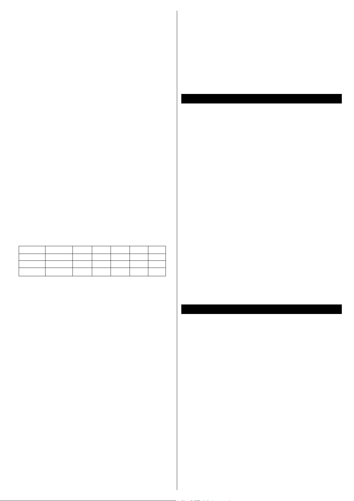
4. Make sure the battery is not connected to the receiver.
Referring to the label on the side of the receiver and the
table below, configure the “SEL” output on the Rx as
needed to match the radio type, turn on the transmitter
and then connect the battery to the receiver.
Note: If the receiver is turned on first then the shunt is
inserted, the JR configuration will not be set. Therefore,
insert the shunt onto the “SEL” output BEFORE turning
on the receiver. Again, do NOT insert the shunt onto the
other connectors, as the power of the battery will be
shorted and the receiver will be permanently damaged.
5. Make sure all servos operate in the proper directions
according to the movement of the Tx stick. When the
Tx stick is at center position, the servo horn should
be perpendicular to the servo itself. When connected
to the airplane's control surface, it should be at
neutral position when the stick is at center. If neutral
position of the control surface has changed, even
though the stick is still at center, change the length
of the pushrod by adjusting the clevis on the end of
the rod. Make sure each control surface is set per the
instructions of your airplane.
6. Turn off the system, receiver first, then transmitter.
7. Range test the radio system prior to flight. Because
electric motors generate electrical noise it is critical to
range test the airplane with the motor on. With the
transmitter antenna collapsed and a helper holding the
airplane, operate the flight controls while walking away
from the airplane. Acceptable range should be
approximately 75' to 100' away before losing control of
the airplane. Next, check the range with the motor
running at half throttle. The range should be close to
the range observed with the motor off. If not, it may be
necessary to move the Rx/ESC, antenna, or servo leads
to a different location. Refer to the Troubleshooting
Guide at the end of this manual if problems exist
during the range check.
Before you begin this step, remove the propeller from the
motor and adjust the transmitter to achieve proper forward
and neutral points.
1. Move the throttle stick to idle (towards you).
2. Switch on the transmitter.
3. Connect the battery to the ESC. The idle or motor
off is now set, signaled by one short beep.
4. Move the throttle stick to full power (away from
you). The ESC will beep twice, indicating full power
has been set.
6. Move the throttle stick back to idle (towards you).
The ESC will beep once.
7. The ESC is now ready to operate.
8. As a safety precaution to prevent the motor from
starting when the ESC is first powered on, you will
need to move the throttle to full and off every time
the ESC is switched on.
RECEIVER
Number of channels: 5
Receiving frequencies:
*72MHz - see Rx label for tuning arrangement:
72MHz low = 72.010 - 72.490MHz (ch 11 – 35)
72MHz high = 72.510 - 72.990MHz (ch 36 – 60)
Filters: single conversion, narrow-band
Intermediate frequency: 455kHz
Receiving range: 890 feet ground maximum
Avg. current drain: 12.0mA (no servo or ESC load)
Sensitivity: 3.0 microvolts
Selectivity: 6dB at +/-3kHz
Input power: 3.0 - 10.0V DC
Dimensions: 0.7"x0.59"x1.5" (18x15x36mm)
Weight: 30g (1.05oz -without crystal)
FCC ID#: IYFR5FM-72
ELECTRONIC SPEED CONTROL
Max. Rated Current: 30 amps
BEC Voltage: 5V / 1.5A
Low Voltage Cutoff: 4.8V
Battery Plug: Standard Type
Switching Frequency: 1.5 kHz
SPECIFICATIONS
SPEED CONTROL SET-UP
Tx Type “SEL” “1” “2” “3” “4” “5”
FUT, HIT No shunt AIL ELEV ESC RUD AUX
AIR No shunt ELEV AIL ESC RUD AUX
JR Shunt in ESC AIL ELEV RUD AUX
This device complies with part 15 of the FCC rules.
Operation is subject to the following two conditions:
1. This device may not cause harmful interference.
2. This device must accept any interference
received, including interference that may cause
undesired operation.
The user is cautioned that changes or modifications not
expressly approved by the party responsible for
compliance could void the user's authority to operate
the equipment.
1. Possible causes and cures for no response:
a. Proper crystal. Make sure crystal is a Futaba®
brand single conversion FM crystal.
b. Do Tx and Rx crystal frequencies match?
c. Is receiver battery dead? Replace or fully charge
the battery.
d. Was the transmitter powered up before the receiver?
2. Possible causes and cures for short receiver range.
a. Collapsed or loose Tx antenna. Fully extend
antenna and make sure it is tight.
b. Interference. Check frequencies in area. Check
Rx installation
c. Rx antenna poorly routed. Re-route antenna away
from other wiring.
d. Severed Rx antenna. Send to Hobby Services for
new antenna.
e. Low Tx or Rx battery. Fully charge batteries prior
to use.
f. Rx or Tx out of tune. Send to Hobby Services
for re-tuning.
g. Crash damage. Send to Hobby Services for
inspection and repair.
h. Faulty Rx or Tx crystal. Install new crystal and
perform range check.
3. Possible causes and cures for interference, glitching
servos, or uncontrollable ESC operation:
a. Another system is operating on your channel. Do
not operate your system until other user is finished.
b. Outside environmental interference. Check local R/C
club to learn of dangerous frequencies in your area.
c. Engine or motor noise. Re-route antenna or servo
leads as far away from motor as possible. Install
good quality capacitors on the motor to filter
electrical noise.
d. Malfunctioning servo. Replace servo and try again.
e. Improper transmitter set-up. Re-set speed control
set-up with the transmitter.
f. The three motor capacitors are not installed
correctly or have broken.
g. The motor battery/ESC plugs do not fit tightly.
4. Possible causes and cures for inoperative ESC circuitry:
a. Weak input power. Make sure motor battery
is charged.
b. Poor electrical contacts. Make sure the plug between
the motor battery and ESC are making good contact.
5. Possible causes and cures for motor failures after
only a few minutes of operation:
a. The propeller may be too large, causing high
current draw and overheating the speed control.
The thermal cutoff is switching the motor off.
b. The motor may be damaged (bent shaft, tight bearing
or shorted winding) causing high current draw.
c. The ESC may need more cooling air flowing over it.
6. Possible causes and cures for motor spinning
in the reverse direction: The ESC is wired to the
motor backwards.
Note: Rx/ESCs that operate normally when received
will be charged a minimum service fee and return
shipping charges. Before sending your ESC in for
service, it is important that you review the Trouble-
Shooting Guide completely The ESC may appear to have
failed when other problems exist in the system - such as
a defective transmitter, receiver or servo, or incorrect
adjustments/installation. Hobby dealers are not
authorized to replace ESCs thought to be defective. Do
not cut the input wires or switch harness of the ESC
before sending it for service. A fee will be charged for cut
wires which must be replaced for testing.
1-YEAR LIMITED WARRANTY
*U.S.A. and Canada Only
Great Planes warrants this product to be free from defects
in materials and workmanship for a period of one (1) year
from the date of purchase. During that period, Great Planes
will, at its option, repair or replace without service charge
only product deemed defective due to those causes. You will
be required to provide proof of purchase (invoice or receipt)
for warranty service. This warranty does not cover damage
caused by abuse, misuse, alteration or accident. If there is
damage stemming from these causes within the stated
warranty period, Great Planes will, at its option, repair or
replace it for a service charge not greater than 50% of its
then current retail list price. Be sure to include your
daytime telephone number in case we need to contact you
about your repair. This warranty gives you specific rights.
You may have other rights, which vary from state to state.
For service on your Great Planes product, warranty or
non-warranty, send it post-paid and insured to:
Hobby Services
1610 Interstate Drive
Champaign, IL 61822
Phone: (217) 398-0007
Made in Korea
WARRANTY
SERVICE PROCEDURES
TROUBLESHOOTING GUIDE
FCC STATEMENT
Entire Contents © Copyright 2002 GPMZ0246 For GPML0056 – 0057 V1.0

This manual suits for next models

1

Popular Receiver manuals by other brands

New Focus 1544-B user guide

New Focus

New Focus 1544-B user guide

Lanzar VBD1900MP owner's manual

Lanzar

Lanzar VBD1900MP owner's manual

PCB Piezotronics JM352C67/M000-50AD Installation and operating manual

PCB Piezotronics

PCB Piezotronics JM352C67/M000-50AD Installation and operating manual

Harman Kardon STEREO RECITAL TA224 Instructional manual

Harman Kardon

Harman Kardon STEREO RECITAL TA224 Instructional manual

Prevail-Catv WR1002RJL manual

Prevail-Catv

Prevail-Catv WR1002RJL manual

Nokia MEDIAMASTER 9460 S owner's manual

Nokia

Nokia MEDIAMASTER 9460 S owner's manual

Berker 8516 51 00 Operation instructions

Berker

Berker 8516 51 00 Operation instructions

Kramer PT-580T user manual

Kramer

Kramer PT-580T user manual

NPG Real DSTR-4000 SD user manual

NPG

NPG Real DSTR-4000 SD user manual

CAMBRIDGE CXR120 Reference

CAMBRIDGE

CAMBRIDGE CXR120 Reference

Sur-Gard SG-MLR2-E Installation and operation manual

Sur-Gard

Sur-Gard SG-MLR2-E Installation and operation manual

NAD T 787 owner's manual

NAD

NAD T 787 owner's manual

Kathrein UFD 345 Mode d'emploi

Kathrein

Kathrein UFD 345 Mode d'emploi

Yamaha RX-V340 owner's manual

Yamaha

Yamaha RX-V340 owner's manual

PCB Piezotronics 080B197 Installation and operating manual

PCB Piezotronics

PCB Piezotronics 080B197 Installation and operating manual

Imperial BAD 1 quick start guide

Imperial

Imperial BAD 1 quick start guide

JVC RX-6000VBK instructions

JVC

JVC RX-6000VBK instructions

Grundig DTR 1782 VC user manual

Grundig

Grundig DTR 1782 VC user manual

manuals.online logo
manuals.online logoBrands
  • About & Mission
  • Contact us
  • Privacy Policy
  • Terms and Conditions

Copyright 2025 Manuals.Online. All Rights Reserved.