Allmatic B.RO X40 DISPLAY User manual

MADE IN ITALY
B.RO X40 DISPLAY
4 channels Rolling Code receiver, with
display.

2/20 6-1620020 rev.0 27/10/2015
ITA ENG FRA ESP DEU POR
ENG
B.RO X40 Display is a 4-channels Rolling Code receiver compatible with all Allmatic Rolling Code remotes. This device has an easy
and intuitive functioning thanks to the display interface and 3 buttons. 4 relay outputs are available with dry contact normally open
(N.O.) and/or closed (N.C.). Outputs can work with 4 different modes: dead man, step by step, timed and timed with delay. Each
output can be controlled by a dedicated wired input or by a single key of a memorized transmitter. The output function is directly
associated to the input command and no to the relay.
The learning of a key of a transmitter can be realized with 3 procedures: default learning (customizable), sequential and advanced.
Power supply 12-24 Vdc/Vac with automatic selection of the voltage.
CONNECTIONS
1-5: wired input (N.O. contact) for relay 1.
2-5: wired input (N.O. contact) for relay 2.
3-5: wired input (N.O. contact) for relay 3.
4-5: wired input (N.O. contact) for relay 4.
6-7: power supply.
8-9: relay output 1 (N.O. contact).
9-10: relay output 1 (N.C. contact).
11-12: relay output 2 (N.O. contact).
12-13: relay output 2 (N.C. contact).
14-15: relay output 3 (N.O. contact).
15-16: relay output 3 (N.C. contact).
17-18: relay output 4 (N.O. contact).
18-19: relay output 4 (N.C. contact).
20: antenna braiding.
21: antenna.
1
2
DISPLAY
UP
MENU
DOWN
+ -
INPUTS LED
OUT1 OUT2 OUT3 OUT4
IN1 (NO)
COM
IN2 (NO)
IN3 (NO)
IN4 (NO)
POWER SUPPLY
12-24 Vdc-Vac
NC1
COM1
NO1
NC2
COM2
NO2
NC3
COM3
NO3
NC4
COM4
NO4
1 2 3 4 5 6 7 8 9 10 11 12 13 14 15 16 17 18 19
20 21
OUTPUTS LED
RADIO MODULE
MEMORY
ELECTRICAL CONNECTIONS
DESCRIPTION
Please read this instruction manual very carefully before installing and programming your control unit.
After the installation keep this instruction in a safe place for any further consultation.
• The device must not be used by people (children included), whose physical, sensory and mental capacities are reduced, or without
experience or knowledge, unless they could bene!t through the intermediation of a person responsible for their safety, of a
surveillance or of instructions related to the use of the device.
• Children must be kept under surveillance to make sure that they do not play with the device.
• If the power supply’s cable is damaged, it must be replaced by the manufacturer or by his assistance service or in any case by a
person with similar status in order to prevent any risk.
• This instruction manual is only for quali!ed technicians, who specialize in installations and automations.
• The contents of this instruction manual do not concern the !nal user.
• Every programming and/or every maintenance service should be done only by quali!ed technicians.
• The installer must provide the installation of a device (es. magnetothermical switch) that ensures the omnipolar sectioning of the
equipment from the power supply.
REMARKS

3/20
6-1620020 rev.0 27/10/2015
ITA ENG FRA ESP DEU POR
ENG
3
BBBB
Make sure that the receiver is out from any menu.
The display shows:
Press briefly the UP (+) button.
The display shows:
GUDG
S
Press a key of the transmitter.
The display shows the position in the memory, for example:
GRQH
The display shows:
Otherwise, if the remote is already memorized, a new learning restores the
transmitter to the default values and the display shows:
IRXQG
GUDG
The receiver waits for a new transmitter.
The display shows:
To quit, press briefly the UP (+) button or wait 10s of inactivity.
The device has available 3 modality for the learning of a transmitter:
• Default learning - press briefly the UP (+) button for the activation.
• Sequential learning - press briefly the DOWN (-) button for the activation.
• Advanced learning - press briefly the MENU button for the activation.
ATTENTION: outputs are disabled during the learning.
3.1 - DEFAULT LEARNING
The default learning memorizes all keys of a remote control with a single press of a key.
The memorized transmitter will have the same settings of the default transmitter. The default transmitter is stored in the memory
and his parameters could be personalized inside the modif menu with the selection of the pdef position (see paragraph 4.2).
If the remote is already memorized, a new learning restores the transmitter to the default values.
The receiver exits from the learning phase after 10 seconds of inactivity or with the press of the UP (+) button.
LEARNING OF A TRANSMITTER
NOTE.
The default transmitter leaves the factory with the following settings:
- Key 1 (b01) activates OUT1 output (CH01) with dead man function (F00).
- Key 2 (b02) activates OUT2 output (CH02) with dead man function (F00).
- Key 3 (b03) activates OUT3 output (CH03) with dead man function (F00).
- Key 4 (b04) activates OUT4 output (CH04) with dead man function (F00).
- Keys from 5 to 16 (b05...b16) are with dead man function (F00), but they are not associated to any outputs.
ATTENTION: with the default learning, B.RO OVER and TECH3 PLUS transmitters are associated to outputs in this way:
- Upper key (b01) activates OUT1 output (CH01) with dead man function (F00).
- Central key (b03) activates OUT3 output (CH03) with dead man function (F00).
- Lower key (b02) activates OUT2 output (CH02) with dead man function (F00).

4/20 6-1620020 rev.0 27/10/2015
ITA ENG FRA ESP DEU POR
ENG
BBBB
Make sure that the receiver is out from any menu.
The display shows:
Press brie•y the DOWN (-) button.
The display shows:
VUDG
S
Press a key of the transmitter.
The display shows the position in the memory, for example:
GRQH
The display shows:
Otherwise, if the remote is already memorized, the display shows:
IRXQG
VUDG
The receiver waits for a new key to be memorized.
The display shows:
To change the selected channel, press and release the DOWN (-) button until the
lighting of the corresponding LED.
OUT1, OUT2, OUT3 and OUT4 LEDS indicate the involved channel during the
learning.
For the selection of the channel press and release the DOWN (-) button until the
lighting of the corresponding LED.
To quit, press and release DOWN (-) button until you switch off of all LEDs of the
outputs or wait 10s of inactivity.
3.2 - SEQUENTIAL LEARNING
The sequential learning memorizes the single key of a transmitter and it associates the key on the desired output.
To the stored key is assigned the DEAD MAN function.
The receiver exits from the learning phase after 10 seconds of inactivity or with the multiple press of the DOWN (-) button.
This learning is activated also with the press of the hidden key of a stored remote control. For the selection of the desired output,
press more times the hidden key.

5/20
6-1620020 rev.0 27/10/2015
ITA ENG FRA ESP DEU POR
ENG
BBBB
Make sure that the receiver is out from any menu.
The display shows:
Press brie•y the MENU button.
The display shows:
DUDG
S
Select the location of the transmitter in the memory with UP (+) and
DOWN (-) buttons of the receiver.
The display shows:
Otherwise, if the remote is already memorized in that location, the display shows:
With UP (+) and DOWN (-) buttons it is possible to change the location where a
transmitter is stored.
QHZ
Press a key of the transmitter.
The display shows:
Otherwise, if the remote is already memorized, the display shows:
IRXQG
S
)
Press and hold the MENU button until the display shows:
if the key is already memorized, the display shows the previous function of the
key:
Select the function of the key with UP (+) and DOWN (-) buttons.
)
)
)
&+
Press and hold the MENU key until the display shows:
Enable/disable the key of the transmitter in the channel 1 with UP (+) and
DOWN (-) buttons of the receiver.
If the key is enabled, the display shows:
&+
3.3 - ADVANCED LEARNING
The advanced learning memorizes the single key of a transmitter.
During the learning phase it is possible to set the parameters of the memorized remote control. See paragraph 4for more information
about single parameters.
The receiver exits from the learning phase after 10 seconds of inactivity or with the press of the MENU button.

6/20 6-1620020 rev.0 27/10/2015
ITA ENG FRA ESP DEU POR
ENG
DUDG
The receiver waits for a new key to be memorized.
The display shows:
To quit, press brie•y the MENU button or wait 10s of inactivity.
&+
Press and hold the MENU button until the display shows:
Enable/disable hte key of the transmitter in the channel 2 with UP (+) and
DOWN (-) buttons of the receiver.
If the key is enabled, the display shows:
&+
Press and hold the MENU button until the display shows:
VDYHG
&+
Press and hold the MENU button until the display shows:
Enable/disable hte key of the transmitter in the channel 3 with UP (+) and
DOWN (-) buttons of the receiver.
If the key is enabled, the display shows:
&+
&+
Press and hold the MENU button until the display shows:
Enable/disable hte key of the transmitter in the channel 4 with UP (+) and
DOWN (-) buttons of the receiver.
If the key is enabled, the display shows:
&+
WARNING: the short pressure of the MENU button during the parameter selection returns the process to the previous point. For
example: the brief pressure of the MENU button in channel 1 enabling menu (the display shows CH01) returns the process to the
selection of the function (the display shows F00 or the last function selected).

7/20
6-1620020 rev.0 27/10/2015
ITA ENG FRA ESP DEU POR
ENG
4
BBBB
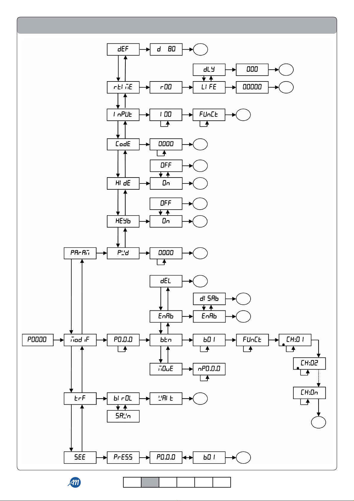
To enter inside the base menu, press the MENU button for at least 1 second.
After the MENU button is pressed, the password is requested, if it has been set (see paragraph 4.1.1).
Use UP (+) and DOWN (-) buttons to move inside the items of the menu, while with the long pressure of the MENU button it is
possible to:
• enter the following group of parameters;
• enter the following step of the running process, or !nish the procedure if it is in the last step (the changes are saved;
• enter the change mode, in the case of parameters that can be changed;
• save the parameter just modi!ed.
During the change of the selected parameter, the value starts blinking. It is possible to change its value with the use of the UP[+] and
DOWN[-] buttons. Instead, with a short pressure of the MENU button it is possible to:
• cancel the change of the parameter in progress;
• go to the previous group of parameters;
• go to the previous step of the procedure in progress.
To quit the menu, press brie"y the MENU button until the display shows , or wait 1 minute of inactivity.
MENU
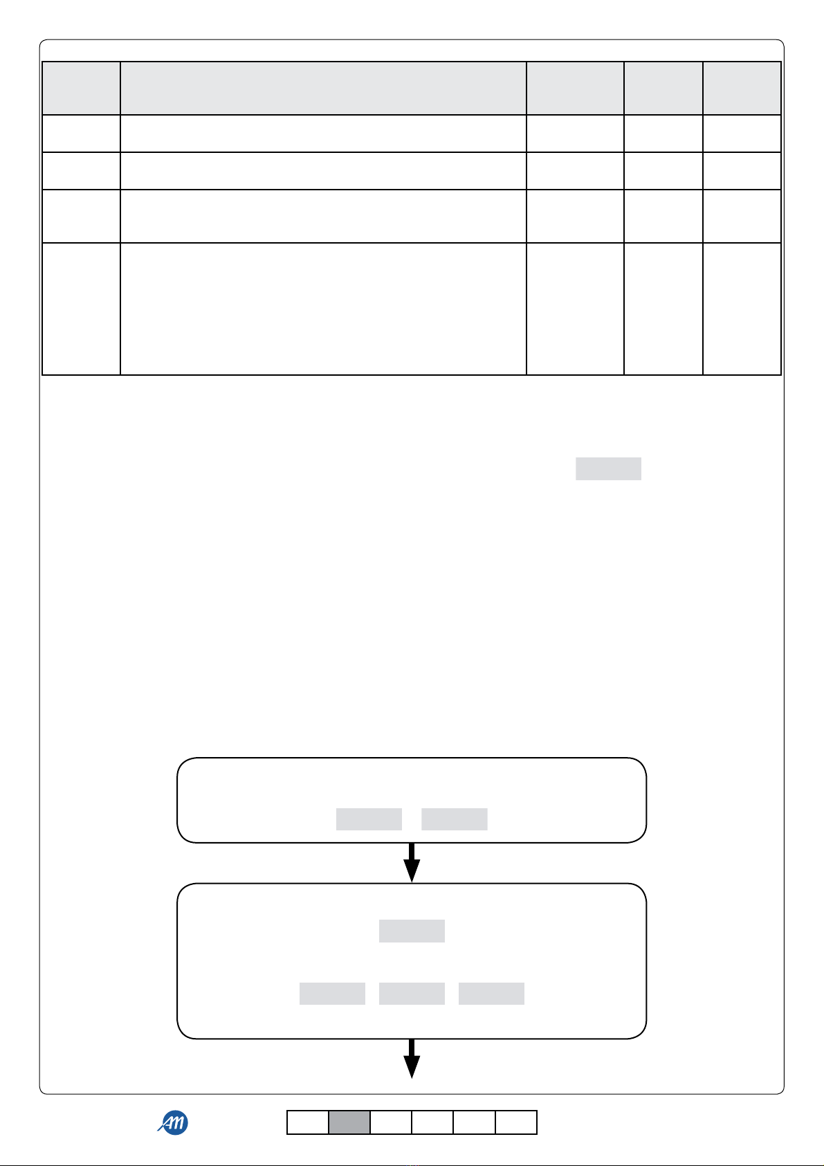
MENU DESCRIPTION
PARAM
PARAMETERS OF THE RECEIVER
Sub-menu of the receiver where it is possible to:
- set the password (PWD);
- enable/disable the learning of the transmitters through the buttons in the receiver (HEYB);
- enable/disable the hidden key of the transmitters (HIde);
- set the function associated to a single wired input (Input);
- set the time and the delay of the outputs that are used with Timed function or Timed+Delay function (rtime);
- reset the receiver to default settings (def).
MODIF PERSONALIZATION OF THE TRANSMITTERS
Sub-menu where it is possible to change all the parameters of a remote control that is located in the memory.
TRF
RESET OF THE TRANSMITTERS
It erases from the memory all the memorized transmitters. During this process it is possible to select the type of
coding that you want to set to the receiver:
- biroL: Rolling Code Allmatic;
- sawn: Custom.
SEE
CHECKING MODE OF THE REMOTE CONTROL
It checks if the transmitter is memorized and shows:
- the location in the memory;
- the index of the pressed key;
- the outputs that are associated to the key.
MENU DESCRIPTION
SELECTABLE
VALUES
min-max
DEFAULT UNIT
Pwd PASSWORD
Value for the protection of the menu. 0(OFF)-9999 OFF
HEYb
LEARNINGS
It is possible to enable or disable the learnings of the transmitters
through buttons in the receiver.
ON-OFF ON
HIde HIDDEN KEY (only with biroL coding)
It is possible to enable or disable the hidden key of transmitters. ON-OFF ON
InPUT
PARAMETERS FOR THE WIRED INPUT
With the selection of the wired input (I01, I02, I03 o I04) you can
associate to it the output function (FUnCT):
- 0: Dead Man;
- 1: Step by Step;
- 2: Timed;
- 3: Timed+Delay.
0-3 0
4.1 Param - SUB-MENU FOR PARAMETERS

8/20 6-1620020 rev.0 27/10/2015
ITA ENG FRA ESP DEU POR
ENG
,QSXW
Go to the menu item Input.
The display shows:
Select the wired input using the UP (+) and DOWN (-) buttons of the receiver.
The display shows:
or or or
,
Select the wired input using the UP (+) and DOWN (-) buttons of the receiver.
The display shows:
Press and hold the MENU button
until the display shows:
IXQ&7
,
,
,
Press and hold the MENU button until the parameter blinks.
Select the desired function with the UP (+) and DOWN (-) buttons of the receiver.
Con!rm the change with a long pressure of the MENU button.
,
,
,
,
4.1.1 PWD - PASSWORD
The menu of the receiver can be protected by a password that will be requested at every login attempt.
This is shown in the display with P0000 and the !rst digit blinking. To change the digit you can use the UP (+) and DOWN (-) buttons.
To move to the next digit press brie"y the MENU button. At the end of the procedure, if the password is correct you will enter the
menu, otherwise the display will show: P Err.
After 1 minute of inactivity the password will be re-enabled.
ATTENTION: it is not possible to delete a forgotten password. You will need a recovery procedure by the manufacturer.
4.1.2 Heyb - LEARNINGS
It is possible to enable or disable all the learnings. These are the only active functionality that does not require a password (if
enabled): in this way you add a further degree of protection to the receiver.
4.1.3 HIde - HIDDEN KEY (only with biroL coding)
It is possible to enable or disable the hidden button of the transmitters. This button allows you to enter the sequential learning/
delete the remote control.
4.1.5 Input - WIRED INPUTS PARAMETERS
It allows to associate to each wired input an output function.
There are 4 different functions:
- 0: Dead Man;
- 1: Step by step;
- 2: Timed;
- 3: Timed + Delay.
To change the parameter please follow the procedure below:
MENU DESCRIPTION
SELECTABLE
VALUES
min-max
DEFAULT UNIT
rtIme
PARAMETERS FOR OUTPUTS
Sub-menu where you can:
- set the activation time of the output with the Timed function or
Timed+Delay function (LiFE);
- set the delay time for the Timed+Delay function (dLy).
LiFE
1-65535
dLy
0-255
LiFE
5
dLy
2
s
def RESET OF THE PARAMETERS
It restores the receiver to default settings.

9/20
6-1620020 rev.0 27/10/2015
ITA ENG FRA ESP DEU POR
ENG
4.1.6 rtime - OUTPUT PARAMETERS
In this sub-menu, for each relay (r01, r02, r03 o r04) it is possible to change the activation duration (LIFE) and the output delay
time (dLy).
To change the parameters, please follow the procedure below:
4.1.7 def - PARAMETERS RESET
By accessing the item def it is possible to restore the default values of the receiver. This reset does not delete the password and the
transmitters registered in the memory except for the parameters of the default transmitter.
In order to proceed with the reset, move to the item def and then con!rm with a long pressure of the MENU button. Keep pressed
until the display shows the value 0, then release the button. Keep pressed again the MENU button: a countdown starts d80, d79, …,
d01, d00. Once the countdown ends, the reset has successfully been performed, and the display shows .
4.2 Modif - TRANSMITTER PERSONALIZATION
By accessing the item ModiF it is possible to customize the transmitters in the memory.
In order to proceed with the change, move to the item Modif, and then con!rm with a long pressure of the MENU button.
Keep pressed until the display shows the !rst position occupied by a transmitter (e.g. p0.0.0), then release the button. The positions
of the memory occupied by a transmitter are indicated by the presence of a point between the digits (for example P0.0.1).
The default transmitter, used during the learning (see section 3.1), is indicated in the memory as Pdef: it is possible to change its
characteristics as for any other remote control, but it cannot be moved/deleted/enabled.
Pdef is located before the position P000.
Use the UP (+) and DOWN (-) buttons to choose the desired transmitter, then con!rm with a long pressure of the MENU button. To
know the location of a speci!c transmitter, use the function SEE (see section 4.4) of the receiver.
Once the transmitter is con!rmed, a sub-menu opens, where it is possible:
UWLPH
Go to the menu item rtime.
The display shows:
Press and hold the MENU button
until the display shows:
or or or
U
Select the output with the UP (+) and DOWN (-) buttons of the receiver.
The display shows:
Press and hold the MENU button until the display shows:
o
/,IH
U
U
U
U
U
U
U
G/\
Select the desired parameter with the UP (+) and DOWN (-) buttons.
Press and hold the MENU button until the parameter blinks.
Set the desired value using the UP (+) and DOWN (-) buttons.
Con!rm the change with a long pressure of the MENU button
GGRQ
10/20 6-1620020 rev.0 27/10/2015
ITA ENG FRA ESP DEU POR
ENG
MENU DESCRIPTION
SELECTABLE
VALUES
min-max
DEFAULT UNIT
deL REMOVAL OF THE TRANSMITTER
It allows the removal of the single transmitter.
enab ENABLING OF THE TRANSMITTER
It allows to enable or disable the transmitter. ON-OFF ON
move
MOVING OF THE TRANSMITTER
It allows to move the location where the transmitter has been
registered in the memory.
000-999
btn
BUTTONS PERSONALISATION
By selecting the button (b01, b02, ..., b15, b16) it is possible:
• to associate the output function (FUnCT):
- F00: Dead Man;
- F01: Step by Step;
- F02: Timed;
- F03: Timed+delay.
• to associate output channels (CH01, CH02, CH03, CH04).
4.2.1 deL - REMOVAL OF THE TRANSMITTER
By accessing the item deL it is possible to delete the single transmitter from the receiver.
In order to proceed with the removal, move to the item deL and then con!rm by a long pressure of the MENU button. Keep pressed
until the display shows the value 0, then release the button. Hold again the MENU button: a countdown starts d20, d19, …, d1, d0.
Once the countdown ends, the reset has successfully been performed, and the display shows .
4.2.2 enAb - ENABLING OF THE TRANSMITTER
It allows to enable or disable the single transmitter. This function serves to disable the transmitter during a period of time, without
removing it from the memory and thus maintaining the con!gured characteristics.
4.2.3 Move - MOVING OF THE TRANSMITTER
It allows to move the position of the transmitter in the receiver’s memory.
In order to proceed with the change, move to the item Move, then con!rm with a long pressure of the MENU button. Keep pressed
until the display shows the !rst free position (e.g. p000), then release the button. The positions of the memory occupied by a
transmitter are indicated by the presence of a point between the digits (for example P0.0.1).
Use the UP (+) and DOWN (-) buttons to select the desired position and con!rm by a long pressure of the MENU button. Keep
pressed until the display shows the value Moved, then release the button.
4.2.4 btn - BUTTONS PERSONALISATION
It allows to personalize the transmitter’s single button. It is possible to associate the function and the output channels (even more
than 1) to each transmitter’s button.
Please follow the procedure below to proceed with the changes:
&/HDU
Select the button to modify with the UP (+) and DOWN (-) buttons of the receiver.
The display shows:
-
)
Press and hold the MENU button until the display shows:
If the key was already saved, the display can show the function previously
assigned:
Select the desired function with the UP (+) and DOWN (-) buttons.
)
)
)
E
E

11/20
6-1620020 rev.0 27/10/2015
ITA ENG FRA ESP DEU POR
ENG
&+
Press and hold the MENU button until the display shows:
Enable/disable the transmitter key in the output channel 1 with the UP (+) or
DOWN (-) buttons of the receiver.
If the button is enabled, the display shows:
&+
S
The receiver returns to the selection screen of the position of the transmitter,
in the position just used. For example:
To quit, press the MENU button or wait one minute of inactivity.
Press and hold the MENU button until the display shows:
VDYHG
&+
Press and hold the MENU button until the display shows:
Enable/disable the transmitter key in the output channel 4 with the UP (+) or
DOWN (-) buttons of the receiver.
If the button is enabled, the display shows:
&+
&+
Press and hold the MENU button until the display shows:
Enable/disable the transmitter key in the output channel 2 with the UP (+) or
DOWN (-) buttons of the receiver.
If the button is enabled, the display shows:
&+
&+
Press and hold the MENU button until the display shows:
Enable/disable the transmitter key in the output channel 3 with the UP (+) or
DOWN (-) buttons of the receiver.
If the button is enabled, the display shows:
&+

12/20 6-1620020 rev.0 27/10/2015
ITA ENG FRA ESP DEU POR
ENG
)GRQ
)HUU
5
6
B
BBB
BBBB
B
BBB
BBBB
ATTENTION: the short pressure of the MENU button during the parameter selection returns the process to the previous point. For
example: the brief pressure of the MENU button in channel 1 enabling menu (the display shows CH01) returns the process to the
selection of the function (the display shows F00 or the last function selected).
4.3 TRf - TRANSMITTERS RESET
By accessing the item TRF it is possible to erase all the transmitters. This reset does not erase the general parameters of the receiver.
To process the reset, move to the item trf then con!rm by pressing and holding the MENU button. Hold until the display shows the
value BiroL, then release the button.
Select the type of encoding that you want to assiociate to the receiver: biroL (Rolling Code) or sawn (Custom).
Con!rm by pressing and holding the MENU button until the display shows the value 0, then release the button. Hold again the
MENU button: a countdown starts d80, d79, …, d01, d00. Once the countdown ends, the reset has successfully been performed, and
the display shows . If the memory is not present, the reset fails and the display shows .
4.4 see - ASSESSMENT METHODS OF THE RADIO CONTROL
By accessing the item SEE it is possible to assess the learning of a remote control, without activating the output relays.
To process the assessment move to the item SEE and then con!rm by pressing and holding the MENU button. Hold until the display
shows the value Press, then release the button.
Press the transmitter’s button. The receiver display shows:
• not, if the transmitter is not learned. After 2 seconds the display shows the index of the pressed key;
• the position of the transmitter in the memory, for example P000 (transmitter not enabled) o P0:00 (transmitter enabled). After
2 seconds the display shows the index of the pressed key and at the same time the LEDs of the outputs associated with the
button.
The receiver returns waiting for a new signal from a transmitter. The display shows Press.
In order to quit, press the MENU button or wait 15sec of inactivity.
Each output can be used with the following functionalities:
- Dead man: the output remains active as long as the button is held down.
- Step by Step: each pressure of the key changes the exit state.
- Timed: when pressing the key, the output gets active for a selectable time (Life). A further pressure during the timing restarts the
timer.
- Timed with delay: when pressing the button, the output is activated after a set time (dLy) and remains active for a selectable time
(Life). A new pressure during the waiting time has no effect; if done while the output is active, instead, it restarts the timer (as in
the Timed case).
ATTENTION: when multiple commands arrive at the same time, the following priorities are given:
1. DEAD MAN;
2. STEP BY STEP;
3. TIMED;
4. TIMED WITH DELAY.
OUTPUTS USING MODE
REPORTS
During the normal functioning, there are two types of output status report: via the display and via the LEDs OUT1, OUT2, OUT3
and OUT4:
The display shows the status of the outputs through four horizontal lines. To each line a relay is associated (the rightmost one is
associated to the relay 4). Reports can be:
• Not-active output: is indicated by an horizontal line in the lower part of the display, for example the relays 1, 2 and 4 not active
or all the relays inactive .
• Active output: is indicated by an horizontal line at the top of the display, for example relay 3 active or all the relays
active .
• Timed active output: is indicated by an horizontal line at the top of the display and in the last 9 seconds it is replaced by a
countdown, e.g. outputs 2 and 4 timed 3 and 6 seconds . .
• Delayed output: is indicated by a horizontal line in the lower part of the display and in the last 9 seconds is replaced by a
countdown, e.g. outputs 2 and 4 delayed 3 and 6 seconds .
The LEDs OUT1, OUT2, OUT3 and OUT4 associate the following functions to the output status:
• Output not active, LED off.

13/20
6-1620020 rev.0 27/10/2015
ITA ENG FRA ESP DEU POR
ENG
7
BBBB
B
BBB
B
BBB
B
BBB
B
BBBB
B
GUDG
VUDG
DUDG
GRQH
QHZ
SGHI
S
S
IRXQG
GGRQ
ZDLW
)GRQ
)HUU
3UHVV
HPH
HPH
HPH
HPH
HPHG
SRZHU
&/HDU
DISPLAY AND STATUS OF THE CONTROL UNITS
Standby.
Outputs not activated.
Output 1 active.
Output 2 active.
Output 3 active.
Output 4 active.
Countdown associated to the output (in the example relay 4).
Displayed during the learning by default.
Displayed during the sequential learning.
Displayed during the advanced learning.
Displayed when a key of a new transmitter has been learned.
Displayed when a key of a new transmitter has been learned during the advanced learning.
Appears when learned one key of a transmitter already learned.
Indicates the position in the default transmitter memory.
Indicates the position in an already-learned transmitter memory.
Indicates a free position in the memory for the learning of a new transmitter.
Appears when the default parameters are restored.
Appears during the cancelation process of all the transmitters.
Appears when all the transmitters are canceled.
Appears when a single transmitter is canceled.
Appears during the reset of the transmitters, if memory is not present.
Appears when the control unit is waiting for a signal from a transmitter during the remote control
assessment mode.
7.1 - NORMAL FUNCTIONING
• Output active, LED on.
• Output active and timed, slow blinking.
• Output delayed waiting for activation, fast blinking.
The receiver will enter the standby mode after 2 minutes of inactivity. The display shows andtheLEDOUTaredisabled.
For exit the mode press briefly a key of the receiver.
Memory not found, not assembled, not electrically functional.
Wrong memory size.
Memory full.
Incorrect coding type or not compatible with the detected memory, or wrong signature.
Wrong identifier code (IdCode).
Supply voltage lower than 8.4 V - possible malfunction of the relays.
7.2 - ERROR REPORTING
14/20 6-1620020 rev.0 27/10/2015
ITA ENG FRA ESP DEU POR
ENG
8FLOWCHART

15/20
6-1620020 rev.0 27/10/2015
ITA ENG FRA ESP DEU POR
ENG
9
DISPLAY
UP
MENU
DOWN
+ -
OUT1 OUT2 OUT3 OUT4
POWER SUPPLY
12-24 Vdc-Vac
NC1
COM1
NO1
NC2
COM2
NO2
NC3
COM3
NO3
NC4
COM4
NO4
1 2 3 4 5 6 7 8 9 10 11 12 13 14 15 16 17 18 19
20 21
PUSH
TO OPEN
PUSH
TO OPEN
PUSH
TO OPEN
EXAMPLE OF USING
9.1 - EXAMPLE 1
Control gate delayed - button with N.O. contact.
I01: FUNCT=3; r01: LIFE=1; DLY=30.
Pedestrian gate control - button with N.O. contact.
I02: FUNCT=0.
Bascule door control - button with N.O. contact.
I03: FUNCT=0.
Bascule door
Electrical lock
pedestrian gate
Gate
Power supply.
4-channels transmitter:
- Key 1 (gate): F00; CH:01; CH02; CH03; CH04.
- Key 2 (pedestrian gate): F00; CH01; CH:02; CH03; CH04.
- Key 3 (bascule door): F01; CH01; CH02; CH:03; CH04.
- Key 4 (gate and bascule door): F01; CH:01; CH02; CH:03; CH04.

16/20 6-1620020 rev.0 27/10/2015
ITA ENG FRA ESP DEU POR
ENG
DISPLAY
UP
MENU
DOWN
+ -
OUT1 OUT2 OUT3 OUT4
POWER SUPPLY
12-24 Vdc-Vac
NC1
COM1
NO1
NC2
COM2
NO2
NC3
COM3
NO3
NC4
COM4
NO4
1 2 3 4 5 6 7 8 9 10 11 12 13 14 15 16 17 18 19
20 21
PUSH
TO OPEN
PUSH
TO OPEN
PUSH
TO OPEN
Shutter control - button with N.O. contact.
I01: FUNCT=0.
Door opener control - button with N.O. contact.
I02: FUNCT=0.
Lighting sign control - light dependent relay with N.O. contact.
I04: FUNCT=2; r03: LIFE=36000 (10 hours).
Lighting sign
Door opener
Shutter
4-channels transmitter:
- Key 1 (shutter): F00; CH:01; CH02; CH03; CH04.
- Key 2 (door opener): F00; CH01; CH:02; CH03; CH04.
- Key 3 (Lighting sign): F01; CH01; CH02; CH:03; CH04.
- Key 4 (road barrier): F00; CH01; CH02; CH03; CH:04.
9.2 - EXAMPLE 2
Road barrier
Road barrier control - button with N.O. contact.
I04: FUNCT=0.
Power supply.

17/20
6-1620020 rev.0 27/10/2015
ITA ENG FRA ESP DEU POR
ENG
Control gate delayed - button with N.O. contact.
I01: FUNCT=3; r01: LIFE=1; DLY=30.
Pedestrian gate control - button with N.O. contact.
I02: FUNCT=0.
2-channels time switch with N.O. contact and impulsive mode.
The irrigation is activated for 30 minutes - I03: FUNCT=2; r03: LIFE=1800.
Theoutdoor lightingisactivatedfor12hours-I04:CH2:FUNCT=2;r04:LIFE=43200.
Outdoor lighting
Irrigation system
Electrical lock
pedestrian gate
Gate
Power supply.
4-channels transmitter:
- Key 1 (gate): F00; CH:01; CH02; CH03; CH04.
- Key 2 (pedestrian gate): F00; CH01; CH:02; CH03; CH04.
- Key 3 (irrigation system): F01; CH01; CH02; CH:03; CH04.
- Key 4 (Outdoor lighting): F01; CH01; CH02; CH03; CH:04.
9.3 - EXAMPLE 3
DISPLAY
UP
MENU
DOWN
+ -
OUT1 OUT2 OUT3 OUT4
POWER SUPPLY
12-24 Vdc-Vac
NC1
COM1
NO1
NC2
COM2
NO2
NC3
COM3
NO3
NC4
COM4
NO4
1 2 3 4 5 6 7 8 9 10 11 12 13 14 15 16 17 18 19
20 21
PUSH
TO OPEN
PUSH
TO OPEN
CANALE 1
CANALE 2
COMUNE

18/20 6-1620020 rev.0 27/10/2015
ITA ENG FRA ESP DEU POR
ENG
9.3.1 - ENTER SETTING STEP BY STEP
• Wired input 1:
1. Press and hold MENU button for at least 1 second.
2. Select the item of the menu param and con!rm the selection by pressing the MENU button for at least 1 second.
3. Select the item of the menu Input and con!rm the selection by pressing the MENU button for at least 1 second.
4. Select the item of the menu I01 and con!rm the selection by pressing the MENU button for at least 1 second.
5. To modify the Funct parameter, press and hold the MENU button for at least 1 second.
6. Set the Funct parameter to 3and con!rm by pressing the MENU button for at least 1 second.
7. Press brie"y the MENU button for 2 times to quit the Input menu.
8. Select the item of the menu rtime and con!rm the selection by pressing the MENU button for at least 1 second.
9. Select the item of the menu r01 and con!rm the selection by pressing the MENU button for at least 1 second.
10. Select the item of the menu LIfe and con!rm the selection by pressing the MENU button for at least 1 second.
11. Set the parameter to 1(1 second) and con!rm by pressing the MENU button for at least 1 second.
12. Select the item of the menu dLy and con!rm the selection by pressing the MENU button for at least 1 second.
13. Set the parameter to 30 (30 seconds) and con!rm by pressing the MENU button for at least 1 second.
14. Press brie"y the MENU button for 4 times to quit the menu.
• Wired input 2:
1. Press and hold the MENU button for at least 1 second.
2. Select the item of the menu param and con!rm the selection by pressing the MENU button for at least 1 second.
3. Select the item of the menu Input and con!rm the selection by pressing the MENU button for at least 1 second.
4. Select the item of the menu I02 and con!rm the selection by pressing the MENU button for at least 1 second.
5. To modify the Funct parameter, press and hold the MENU button for at least 1 second.
6. Set the Funct parameter to 0and con!rm by pressing the MENU button for at least 1 second.
7. Press brie"y the MENU button for 4 times to quit the menu.
• Wired input 3:
1. Press and hold the MENU button for at least 1 second.
2. Select the item of the menu param and con!rm the selection by pressing the MENU button for at least 1 second.
3. Select the item of the menu Input and con!rm the selection by pressing the MENU button for at least 1 second.
4. Select the item of the menu I03 and con!rm the selection by pressing the MENU button for at least 1 second.
5. To modify the Funct parameter, press and hold the MENU button for at least 1 second.
6. Set the Funct parameter to 2and con!rm by pressing the MENU button for at least 1 second.
7. Press brie"y the MENU button for 2 times to quit the Input menu.
8. Select the item of the menu rtime and con!rm the selection by pressing the MENU button for at least 1 second.
9. Select the item of the menu r03 and con!rm the selection by pressing the MENU button for at least 1 second.
10. Select the item of the menu LIfe and con!rm the selection by pressing the MENU button for at least 1 second.
11. Set the parameter to 1800 (30 minutes) and con!rm by pressing the MENU button for at least 1 second.
12. Press brie"y the MENU button for 4 times to quit the menu.
• Wired input 4:
1. Press and hold the MENU button for at least 1 second.
2. Select the item of the menu param and con!rm the selection by pressing the MENU button for at least 1 second.
3. Select the item of the menu Input and con!rm the selection by pressing the MENU button for at least 1 second.
4. Select the item of the menu I04 and con!rm the selection by pressing the MENU button for at least 1 second.
5. To modify the Funct parameter, press and hold the MENU button for at least 1 second.
6. Set the Funct parameter to 2and con!rm by pressing the MENU button for at least 1 second.
7. Press brie"y the MENU button for 2 times to quit the Input menu.
8. Select the item of the menu rtime and con!rm the selection by pressing the MENU button for at least 1 second.
9. Select the item of the menu r04 and con!rm the selection by pressing the MENU button for at least 1 second.
10. Select the item of the menu LIfe and con!rm the selection by pressing the MENU button for at least 1 second.
11. Set the parameter to 43200 (12 hours) and con!rm by pressing the MENU button for at least 1 second.
12. Press brie"y the MENU button for 4 times to quit the menu.
• Learning and setting of the default transmitter with 4 channels:
NOTE: the setting of the default transmitter is necessary only for the first remote control.
1. Press and hold the MENU button for at least 1 second.
2. Select the item of the menu Modif and con!rm the selection by pressing the MENU button for at least 1 second.
3. Select the item of the menu Pdef and con!rm the selection by pressing the MENU button for at least 1 second.
4. Select the item of the menu btn and con!rm the selection by pressing the MENU button for at least 1 second.
5. Select the item of the menu b01 and con!rm the selection by pressing the MENU button for at least 1 second.
6. Select the item of the menu f00 and con!rm the selection by pressing the MENU button for at least 1 second.
7. Enable the key in the CH:01 output and con!rm the selection by pressing the MENU button for at least 1 second.
8. Disable the key in the CH02 output and con!rm the selection by pressing the MENU button for at least 1 second.
9. Disable the key in the CH03 output and con!rm the selection by pressing the MENU button for at least 1 second.
10. Disable the key in the CH04 output and con!rm the selection by pressing the MENU button for at least 1 second.
11. Select the item of the menu Pdef and con!rm the selection by pressing the MENU button for at least 1 second.
12. Select the item of the menu btn and con!rm the selection by pressing the MENU button for at least 1 second.
13. Select the item of the menu b02 and con!rm the selection by pressing the MENU button for at least 1 second.
14. Select the item of the menu f00 and con!rm the selection by pressing the MENU button for at least 1 second.

19/20
6-1620020 rev.0 27/10/2015
ITA ENG FRA ESP DEU POR
ENG
Coding Rolling code
Memorisable transmitters 1000 with dedicated memory
Power supply 12 / 24 Vdc / Vac
Number of outputs 4 N.O./N.C.
Outputs operating modes • Dead Man
• Step by Step
• Timed
• Timed with delay
Number of wired inputs 4 (N.O. contact)
Antenna Tuned at 433.92 MHz
Frequency 433.92 MHz
Range 80 - 250 m (*)
Relay contact 16A a 230 Vac
Temperature of use -10…55 °C
* The radio range depends on the transmitter, the antenna and the interferences on the !eld.
10 TECHNICAL FEATURES
15. Disable the key in the CH01 output and con!rm the selection by pressing the MENU button for at least 1 second.
16. Enable the key in the CH:02 output and con!rm the selection by pressing the MENU button for at least 1 second.
17. Disable the key in the CH03 output and con!rm the selection by pressing the MENU button for at least 1 second.
18. Disable the key in the CH04 output and con!rm the selection by pressing the MENU button for at least 1 second.
19. Select the item of the menu Pdef and con!rm the selection by pressing the MENU button for at least 1 second.
20. Select the item of the menu btn and con!rm the selection by pressing the MENU button for at least 1 second.
21. Select the item of the menu b03 and con!rm the selection by pressing the MENU button for at least 1 second.
22. Select the item of the menu f01 and con!rm the selection by pressing the MENU button for at least 1 second.
23. Disable the key in the CH01 output and con!rm the selection by pressing the MENU button for at least 1 second.
24. Disable the key in the CH02 output and con!rm the selection by pressing the MENU button for at least 1 second.
25. Enable the key in the CH:03 output and con!rm the selection by pressing the MENU button for at least 1 second.
26. Disable the key in the CH04 output and con!rm the selection by pressing the MENU button for at least 1 second.
27. Select the item of the menu Pdef and con!rm the selection by pressing the MENU button for at least 1 second.
28. Select the item of the menu btn and con!rm the selection by pressing the MENU button for at least 1 second.
29. Select the item of the menu b04 and con!rm the selection by pressing the MENU button for at least 1 second.
30. Select the item of the menu f01 and con!rm the selection by pressing the MENU button for at least 1 second.
31. Disable the key in the CH01 output and con!rm the selection by pressing the MENU button for at least 1 second.
32. Disable the key in the CH02 output and con!rm the selection by pressing the MENU button for at least 1 second.
33. Disable the key in the CH03 output and con!rm the selection by pressing the MENU button for at least 1 second.
34. Enable the key in the CH:04 output and con!rm the selection by pressing the MENU button for at least 1 second.
35. Press brie"y MENU button for 2 times to quit the menu.
36. Press brie"y the UP (+) button to carry out the default learning.
37. Press the key of the transmitter that you want to memorize.
GUARANTEE
In compliance with legislation, the manufacturer’s guarantee is valid from the date stamped on the product and is restricted to
the repair or free replacement of the parts accepted by the manufacturer as being defective due to poor quality materials or
manufacturing defects. The guarantee does not cover damage or defects caused by external agents, faulty maintenance, overloading,
natural wear and tear, choice of incorrect product, assembly errors, or any other cause not imputable to the manufacturer. Products
that have been misused will not be guaranteed or repaired.
Printed speci!cations are only indicative. The manufacturer does not accept any responsibility for range reductions or malfunctions
caused by environmental interference. The manufacturer’s responsibility for damage caused to persons resulting from accidents of
any nature caused by our defective products, are only those responsibilities that come under Italian law.

MADE IN ITALY
ALLMATIC S.r.l
32020 Lentiai - Belluno – Italy
Via dell’Artigiano, n°1 – Z.A.
Tel. 0437 751175 – 751163 r.a. Fax 0437 751065
http://www.allmatic.com - E-mail: info@allmatic.com
6-1620020 rev.0 27/10/2015
Other manuals for B.RO X40 DISPLAY
1
Table of contents
Other Allmatic Receiver manuals


Popular Receiver manuals by other brands


Kenwood
Kenwood DPX-M3200BT instruction manual

TV Star
TV Star T1010p user manual

World Time Solutions
World Time Solutions WWVB1000 user manual

Lectrosonics
Lectrosonics M2R instruction manual

ML Accessories
ML Accessories Knightsbridge DC010 Installation and maintenance manual

Onkyo
Onkyo TX-NR636 Basic Manual