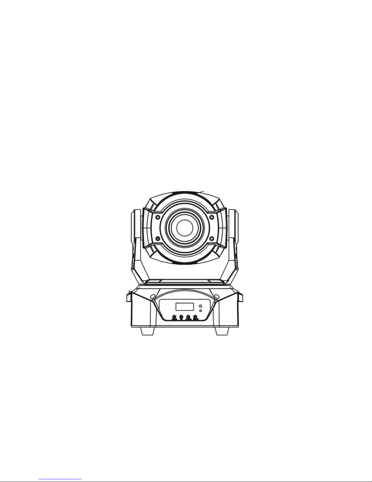
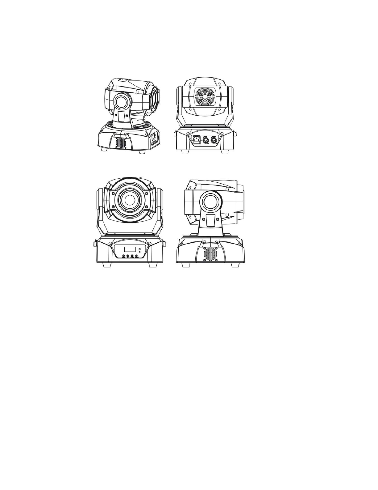
Great Stage Light GLM015 User manual

90W SPOT MOVING HEAD
USER MANUAL

1
TABLE OF CONTENTS
1.BEFORE YOU BEGIN
WHAT IS INCLUDED
UNPACKING NSTRUCTIONS
MANUAL CONVENTIONS
ICONS
SAFETY INSTRUCTIONS
2.INSTRODUCTION
TECHNICAL SPECIFICATION
PRODUCT DIMENSIONS
PRODUCT OVERVIEW
3.SETUP
AC POWER
POWER LINKING
SIGNAL LINKING(DMX)
FUSE REPLACEMENT
MOUNTING ORIENTATION RIGGING
4. OPERATING INSTRUCTIONS
CONFIGURING THE STARTING ADDRESS
CONTROL PANEL FUNCTIONS
MENU MAP
DMX CHANNEL VALUES
5. APPENDIX
DMX PRIMER
GENERAL MAINTENANCE
FIXTURE LINKING
DATA CABLING
DMX DATA CABLE
CABLE CONNECTORS
3-PIN TO 5-PIN CONVERSION CHART
SETTING UP A DMX SERIAL DATA LINK
SETTING THE STARTING ADDRESS
GENERAL TROUBLESHOOTING

2
1. BEFORE YOU BEGIN
What is included
1 x Spot
1 x Mounting bracket and screws
1 x Power cable
1 x User Manual
Unpacking Instructions
Immediately upon receiving a fixture, carefully unpack the carton, check the
contents to ensure that all parts are present, and have been received in good
condition. Notify the shipper immediately and retain packing material for
inspection if any parts appear damaged from shipping or the carton itself
shows signs of mishandling. Save the carton and all packing materials. In the
event that a fixture must be returned to the factory, it is important that the
fixture be returned in the original factory box and packing.
Manual Conventions
manuals use the following conventions to differentiate certain types of
information from the regular text.
Icons
This manual uses the following icons to indicate information that requires
special attention on the part of the user.
CONVENTION
MEANING
[10]
A LCD display to be configured
<Menu>
A key to be pressed on the fixture’s control panel
1~512
A range of values
50/60
A set of values of which only one can be chosen
Settings
A menu option not to be modified (for example,
showing the operating mode/current status)
MENU >Settings
A sequence of menu options to be followed
ON
A value to be entered or selected

3
Safety Instructions
● Please keep this User Manual for future consultation. If you sell the unit
to another user, be sure that they also receive this instruction booklet.
● Always make sure that you are connecting to the proper voltage, and that
the line voltage you are connecting to is not higher than that stated on the
decal or rear panel of the fixture.
● This product is intended for indoor use only! To prevent risk of fire or
shock, do not expose fixture to rain or moisture.
● Make sure there are no flammable materials close to the unit while
operating.
● The unit must be installed in a location with adequate ventilation, at least
20 in (50 cm) from adjacent surfaces. Be sure that no ventilation slots are
blocked.
● Always disconnect from power source before servicing or replacing fuse
and be sure to replace with same fuse source.
● Secure fixture to fastening device using a safety chain.
● Maximum ambient temperature (Ta) is 104° F (40° C). Do not operate
fixture at temperatures higher than this.
● In the event of a serious operating problem, stop using the unit
immediately.
Never try to repair the unit by yourself. Repairs carried out by unskilled
people can lead to damage or malfunction. Please contact the nearest
ICONS
MEANING
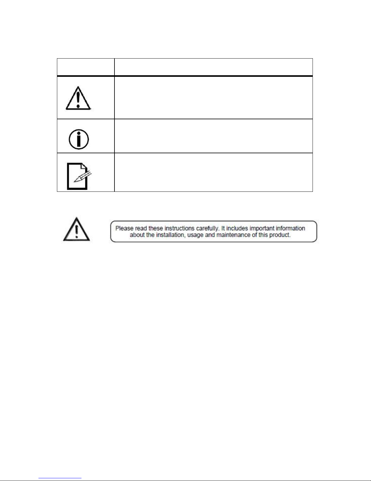
This paragraph contains critical installation, configuration or
operation information. Failure to comply with this
information may render the fixture partially or completely
inoperative, cause damage to the fixture or cause harm to
the user.
This paragraph contains important installation or
configuration information. Failure to comply with this
information may prevent the fixture from functioning
correctly.
This paragraph reminds you of useful, although not critical,
information

4
authorized technical assistance center.
● Never connect the device to a dimmer pack.
● Make sure the power cord is never crimped or damaged.
● Never disconnect the power cord by pulling or tugging on the cord.
● Never carry the fixture directly from the cord. Always use the
hanging/mounting bracket.
● Avoid direct eye exposure to the light source while it is on.
● Never carry the fixture by holding the head. Always use the carrying
handle.
2. INTRODUCTION
Technical Specification
1) Voltage: 100-240V,50-60Hz
2) Power consumption: 110W
3) LED: ultra bright 90W LED
4) LED color wheel: Basic 7 colors+ white, can adjust speed rainbow effect
5) Fixed gobo: 8 gobos+ white, Gobo rotating CW and CCW from slow to
fast), gobo shaking
6) Rotation gobo: 6 gobos + white, can bidirectional speed change
rotation, gobo shaking
7) Dimmer/Strobe: Dimmer, 1-20t/s
8) Focus: Electronic Focus
9) Pan::540° Tilt: 270
10) Control: DMX 512, 14/16 /11CHs
11) Working mode: Stand-alone mode, Controller mode, Master/Slave
synchronization mode
12) Other function: Pan/Tilt speed adjustable
Housing: High temperature resistant engineering plastic + aluminum
alloy.
13) Weight: 6.5KG
14) Product Size: 240*240*370mm
15) Packing Size: 350*340*375mm

5
Product Dimensions

6
Product Overview

7
3. SET UP
AC Power
This fixture runs on 100-240VAC, 50/60 Hz. This fixture used switch power
supply, it can transform by itself when user input power.
Always connect the fixture to a switched circuit. Never connect
the fixture to a rheostat (variable resistor) or dimmer circuit, even if the
rheostat or dimmer channel is used only as a 0 to 100% switch.
Always connect the fixture to a circuit with a suitable electrical
ground.
The maximum quantity of fixtures that may be linked is 4.
Power Linking
This fixture contains power linking via the outlet located in front of the power
input cable. Please see the diagram below for further explanation.

8
Signal Linking (DMX)
The diagrams below illustrate the signal (DMX) linking for this fixture. This is
used both in DMX mode and when operating the fixtures in Master/Slave
mode. Please see the diagram below for further explanation.
Fuse Replacement

9
With a flat head screwdriver unscrew the fuse holder out of its housing,
turning counter-clockwise. Remove the damaged fuse from its holder and
replace with exact same type fuse. Insert the fuse holder back in its place and
reconnect power.
Mounting
Orientation
The Spot may be mounted in any safe position provided there is adequate
room for ventilation.
Rigging
Be sure that the structure can support 10 times the weight of the fixture.
Please see the “Technical Specifications” section of this manual for a detailed
weight listing. Mount the fixture securely. Two hanging clamps for truss
mounting may be used, or nuts and bolts for permanent installation may be
used. The holes in each bracket are 13 mm in size. When rigging, consider
routine maintenance and control panel access. Please see the following steps
for installation.
●If the power link out is intended to be used with multiple fixture, take into
account the length of each power cable, and mount the fixtures close
enough to one another to accommodate for this.
●Attach both included bolts in the locations indicated below, using a metric
8 mm Allen wrench.
●Attached 2 hanging clamps to the bracket in each of the two locations
indicated below
●Safety cables must always be used.

10
Do NOT mount this fixture sideways!

11
4. OPERATING INSTRUCTIONS
Configuring the Starting Address
Each fixture requires a starting address from 1~512. A fixture requiring one or
more channels for control begins to read the data on the channel indicated by
the starting address. For example, a fixture that uses seven DMX channels
and is addressed to start on DMX channel 100, will read data from channels:
100, 101, 102, 103, 104, 105 and 106. Choose the starting addresses for
each fixture so that the channels used do not overlap. In addition, you should
note the starting address selected for future reference.
Control Panel Functions
The Control Panel shows the current state of the unit. It is used to select the
operating mode, as well as the sub-features. For a detailed layout of the
control panel functions, please see the “menu map” section on the following
page.
[MENU] menu selection or return to previous menu.
[UP] press [UP] through the menu list to increase/change the value of the
current function.
[DOWN] press [DOWN] through the menu list to decrease/change the value
of the current function.
[ENTER] confirm & quit out current function setting.
Menu Map

12

13
DMX CHANNEL VALUES
16-Channel Mode
16 CHS
CH value
Function
1CH X rotation
000-255
X rotation 0°-540°
2CH X fine adjustment
000-255
Xfine adjustment
3CH Y rotation
000-255
Y rotation 0°-270°
4CH Y fine adjustment
000-255
Yfine adjustment
5CH X/Y Speed
000-255
XY speed from fast to slow
6CH Dimmer
000-255
From dark to bright
7CH Strobe
0-5
6-249
250-255
ON
Strobe from slow to fast
ON
8CH 7Color + White
0-9
10-180
181-255
White
Colors/ half colors
Rainbow Effect(slow to fast)
9CH Focus
000-255
Focus, from near to far
10CH 6 rotation Gobo wheel
0-19
20-39
40-59
60-79
80-99
100-119
120-139
140-255
White
Gobo 1
Gobo 2
Gobo 3
Gobo 4
Gobo 5
Gobo 6
Gobo rotating CW and CCW
from slow to fast)
11CH Gobo self-rotation
0-19
20-139
140-255
No function
Gobo self-rotating clockwise
from slow to fast
Gobo self-rotating counter-
clockwise from slow to fast
12CH Rotation gobo shaking
000-255
Slow-fast
13CH 8 Static Gobos wheel
0-9
10-19
20-39
40-59
60-79
80-99
100-119
120-139
White
Gobo 1
Gobo 2
Gobo 3
Gobo 4
Gobo 5
Gobo 6
Gobo 7

14
140-159
160-255
Gobo 8
Gobo rotating CW and CCW
from slow to fast
14CH Static gobo shaking
000-255
Slow-fast
15CH Prism
0-19
20-63
64-255
OFF
ON
Forward Rotating from fast to
slow
16CH Reset
1-199
200-219
220-255
No function
Reset after 3 second
No function
14-Channel Mode
14 CHS
CH value
Function
1CH X rotation
000-255
X rotation 0°-540°
2CH X fine adjustment
000-255
Xfine adjustment
3CH Y rotation
000-255
Y rotation 0°-270°
4CH Y fine adjustment
000-255
Yfine adjustment
5CH X/Y Speed
000-255
XY speed from fast to slow
6CH Dimmer
000-255
From dark to bright
7CH Strobe
0-5
6-249
250-255
ON
Strobe from slow to fast
ON
8CH 7Color + White
0-9
10-180
181-255
White
Colors/ half colors
Rainbow Effect(slow to fast)
9CH Focus
000-255
Focus, from near to far
10CH 6 Gobos + White
0-19
20-39
40-59
60-79
80-99
100-119
120-139
140-255
White
Gobo 1
Gobo 2
Gobo 3
Gobo 4
Gobo 5
Gobo 6
Gobo rotating CW and CCW
from slow to fast)
11CH Gobo self-rotation
0-19
No function

15
20-139
140-255
Gobo self-rotating clockwise
from slow to fast
Gobo self-rotating counter-
clockwise from slow to fast
12CH 8 Gobos + White
0-9
10-19
20-39
40-59
60-79
80-99
100-119
120-139
140-159
160-255
White
Gobo 1
Gobo 2
Gobo 3
Gobo 4
Gobo 5
Gobo 6
Gobo 7
Gobo 8
Gobo rotating CW and CCW
from slow to fast
13CH Prism
0-19
20-63
64-255
OFF
ON
Forward Rotating from fast to
slow
14CH Reset
1-199
200-219
220-255
No function
Reset after 3 second
No function
11-Channel Mode
11 CHS
CH value
Function
1CH X rotation
000-255
X rotation 0°-540°
2CH Y rotation
000-255
Y rotation 0°-270°
3CH X/Y Speed
000-255
XY speed from fast to slow
4CH Dimmer
000-255
From dark to bright
5CH Strobe
0-5
6-249
250-255
ON
Strobe from slow to fast
ON
6CH 7Color + White
0-9
10-180
181-255
White
Colors/ half colors
Rainbow Effect(slow to fast)
7CH Focus
000-255
Focus, from near to far
8CH 6 Gobos + White
0-19
20-39
40-59
White
Gobo 1
Gobo 2

16
60-79
80-99
100-119
120-139
140-255
Gobo 3
Gobo 4
Gobo 5
Gobo 6
Gobo rotating CW and CCW
from slow to fast)
9CH Gobo self-rotation
0-19
20-139
140-255
No function
Gobo self-rotating clockwise
from slow to fast
Gobo self-rotating counter-
clockwise from slow to fast
10CH 8 Static Gobos wheel
0-9
10-19
20-39
40-59
60-79
80-99
100-119
120-139
140-159
160-255
White
Gobo 1
Gobo 2
Gobo 3
Gobo 4
Gobo 5
Gobo 6
Gobo 7
Gobo 8
Gobo rotating CW and CCW
from slow to fast
11CH Prism
0-19
20-63
64-255
OFF
ON
Forward Rotating from fast to
slow
5. APPENDIX
DMX Primer
There are 512 channels in a DMX connection. Channels may be assigned in
any manner. A fixture capable of receiving DMX will require one or a number
of sequential channels. The user must assign a starting address on the fixture
that indicates the first channel reserved in the controller. There are many
different types of DMX controllable fixtures and they all may vary in the total
number of channels required. Choosing a start address should be planned in
advance. Channels should never overlap. If they do, this will result in erratic
operation of the fixtures whose starting address is set incorrectly. You can

17
however, control multiple fixtures of the same type using the same starting
address as long as the intended result is that of unison movement or
operation. In other words, the fixtures will be slaved together and all respond
exactly the same.
DMX fixtures are designed to receive data through a serial Daisy Chain. A
Daisy Chain connection is where the DATA OUT of one fixture connects to
the DATA IN of the next fixture. The order in which the fixtures are connected
is not important and has no effect on how a controller communicates to each
fixture. Use an order that provides for the easiest and most direct cabling.
Connect fixtures using shielded two conductor twisted pair cable with three
pin XLR male to female connectors. The shield connection is pin 1, while pin
2 is Data Negative (S-) and pin 3 is Data positive (S+).
General Maintenance
To maintain optimum performance and minimize wear, fixtures should be
cleaned frequently. Usage and environment are contributing factors in
determining frequency. As a general rule, fixtures should be cleaned at least
twice a month. Dust build up reduces light output performance and can cause
overheating. This can lead to reduced lamp life and increased mechanical
wear. Be sure to power off fixture before conducting maintenance.
● Unplug fixture from power.
● Use a vacuum or air compressor and a soft brush to remove dust
collected on external vents.
● Clean all glass when the fixture is cold with a mild solution of glass cleaner
or Isopropyl Alcohol and a soft lint free cotton cloth or lens tissue.
● Apply solution to the cloth or tissue and drag dirt and grime to the outside
of the lens.
● Gently polish optical surfaces until they are free of haze and lint.
The cleaning of external optical lenses and/or mirrors must be carried out
periodically to optimize light output. Cleaning frequency depends on the
environment in which the fixture operates. Damp, smoky or particularly dirty
surroundings can cause greater accumulation of dirt on the unit’s optics.
Clean with soft cloth using normal glass cleaning fluid. Clean the external
optics at least every 20 days. Clean the fixture at least every 30/60 days.
Always dry the parts carefully after cleaning them.

18
Never spin a fan using compressed air.
Fixture Linking
You will need a serial data link to run light shows of one or more fixtures using
a DMX controller or to run synchronized shows on two or more fixtures set to
a master/slave operating mode. The combined number of channels required
by all the fixtures on a serial data link determines the number of fixtures the
data link can support.
Fixtures on a serial data link must be daisy chained in one
single line. To comply with the EIA485 standard, no more than 32
fixtures should be connected on one data link. Connecting more than 32
fixtures on one serial data link without the use of a DMX
optically-isolated splitter may result in deterioration of the digital DMX
signal.
Maximum recommended serial data link distance: 500 m (1640 ft)
Maximum recommended number of fixtures on a serial data link: 32
Data Cabling
To link fixtures together you must obtain data cables. You can purchase
certified DMX cables directly from a dealer/distributor or construct your own
cable. If you choose to create your own cable please use data-grade cables
that can carry a high quality signal and are less prone to electromagnetic
interference.
DMX Data Cable
Use a Belden© 9841 or equivalent cable which meets the specifications for
EIA RS-485 applications. Standard microphone cables cannot transmit DMX
data reliably over long distances. The cable must have the following
characteristics:
Type: shielded, 2-conductor twisted pair
Maximum capacitance between conductors: 30 pF/ft
Maximum capacitance between conductor and shield: 55 pF/ft
Maximum resistance: 20 ohms/1000 ft
Nominal impedance: 100 ~ 140 ohms
Cable Connectors

19
Cabling must have a male XLR connector on one end and a female XLR
connector on the other end.
Do not allow contact between the common and the fixture’s
chassis ground. Grounding the
common can cause a ground loop, and your fixture may perform
erratically. Test cables with
an ohm meter to verify correct polarity and to make sure the pins are not
grounded or shortedto the shield or each other.
3-Pin to 5-Pin Conversion Chart
If you use a controller with a 5-pin DMX output connector, you will
need to use a 5pin to 3-pin adapter. The chart below details a proper
cable conversion:
3-PIN TO 5-PIN CONVERSION CHART
Table of contents
Other Great Stage Light Dj Equipment manuals