Gree FHBQ-D3.5-K User manual

Energy-Recovery Ventilation System
Service Manual
( GC201110-I )
en
Energ
Ve
en
Ve
e
ice
e
e
e M
en
e

II
Energy-Recovery Ventilation
System Service Manual
Contents
PRODUCT ............................................................................................... 2
1 MODELS LIST ....................................................................................................2
2 NOMENCLATURE...............................................................................................2
3 FEATURES..........................................................................................................2
4 PRODUCT DATA.................................................................................................3
5 PIPING DIAGRAM...............................................................................................5
CONTROL................................................................................................ 7
1 OPERATION FLOWCHART................................................................................7
2 MAIN LOGIC .......................................................................................................8
3 WIRED REMOTE CONTROLLER.......................................................................9
INSTALLATION...................................................................................... 18
1 DIMENSION DATA ...........................................................................................18
2 INSTALLATION SITE .......................................................................................19
3 UNIT INSTALL...................................................................................................19
4 CAUTIONS FOR INSTALLATION ....................................................................20
5 ELECTRIC WIRING WORK ..............................................................................21
MAINTENANCE..................................................................................... 24
1 TROUBLE TABLE ............................................................................................24
2 FLOW CHART OF TROUBLE SHOOTING .....................................................25
3 WIRING DIADRAM ...........................................................................................26
4 DISASSEMBLY AND ASSEMBLY PROCEDURE OF MAIN PARTS ...............28
5 EXPLODED VIEWS AND PART LIST...............................................................30

1
Energy-Recovery Ventilation
System Service Manual
PRODUCT
QSPEVDU

2
Energy-Recovery Ventilation
System Service Manual
QSPEVDU
PRODUCT
1 MODELS LIST
1.1 Outdoor Unit
Model Code Air Flow(m3/h) External Static
Pressure (Pa)
Power
Supply Appearance
FHBQ-D3.5-K EH01100010
H 350 H 100
220V
50Hz~
M 260 M 80
L 210 L 60
FHBQ-D5-K EH01100020
H 500 H 100
M 380 M 80
L 300 L 60
FHBQ-D8-K EH01100030
H 800 H 110
M 600 M 85
L 480 L 65
FHBQ-D10-K EH01100040
H 1000 H 110
M 750 M 85
L 600 L 65
FHBQ-D15-M EH01100050 1500 150 380V3N~
50Hz
FHBQ-D20-M EH01100060 2000 150 380V3N~
50Hz
FHBQ-D30-M EH01100070 3000 220 380V3N~
50Hz
2 NOMENCLATURE
FH B Q - D 3.5 - K
123456
NO. Description Options
1The symbol of energy
recovery ventilation /
2 The structure of heat exchanger board
3 The diathermanous mode Total heat exchange
4 The mode of installation Celling mounted type
5 Nominal Air Flow 3.5:350m3/h;5:500 m3/h;
…… ;30:3000 m3/h
6 The phase of power supply K: single-phase;
M:three- phase
3 FEATURES
3.1 Description
Our living environments are more and more affected by modern civilization. As the application of air-
FRQGLWLRQLQJV\VWHPDQGYDULRXVFRPSRVLWHPDWHULDOVSRSXODUL]DWLRQRIRI¿FHHTXLSPHQWVDQGGHYHORSPHQWRI
closeness of constructions and for the purpose of energy saving and reduction of cost which cause decrease of
fresh air volume, harmful gas and pollution of creature won’t be diluted properly and replaced. Healthy, energy-
VDYLQJVLPSOHDQGUHOLDEOHIUHVKDLUV\VWHPDQGHTXLSPHQWKDVEHHQWKHIRFXVIRUHQJLQHHUVDQGXVHUV*UHH
energy recovery ventilation system has solved this problem. This kind of system has two-way air exchange
IXQFWLRQVRWKDWWKHFKDQJHRILQGRRUWHPSLVOLWWOHGXULQJDLUH[FKDQJH7KHLQGRRUDLUFDQEHHI¿FLHQWO\¿OWHUHG
E\WKHDLU¿OWHU1HZWHFKQRORJ\DQGQHZPDWHULDOVDQGVSHFLDOWHFKQLTXHDSSOLHGLQWKHXQLWFDQHQVXUHORZ
energy consumption, great performance ,low noise and easy installation.

3
Energy-Recovery Ventilation
System Service Manual
QSPEVDU
3.2 Standard Features
1. Replacement and Ventilation Function
It introduces fresh air into room and discharges indoor airout of room to make you feel comfortable as in
the nature.
2. Energy-recovery Function
Internal heat exchanger makes the discharged air and introduced air for cooling and heating exchange.
Energy-recovery rate above 70% keeps heat preservation and ventilation realized.
3. Low-noise Design
Special low-noise ventilation fan is set.
4. Air Filtration and Purge Function
,QWHUQDODLU¿OWHUNHHSVWKHIUHVKDLULQWURGXFHGLQWRURRPSXUHDQGGXVWOHVV
5. 9DULRXV6HULHVDQG0XOWLSOH6SHFL¿FDWLRQV
There are various series to match with the buildings of various structures.
4 PRODUCT DATA
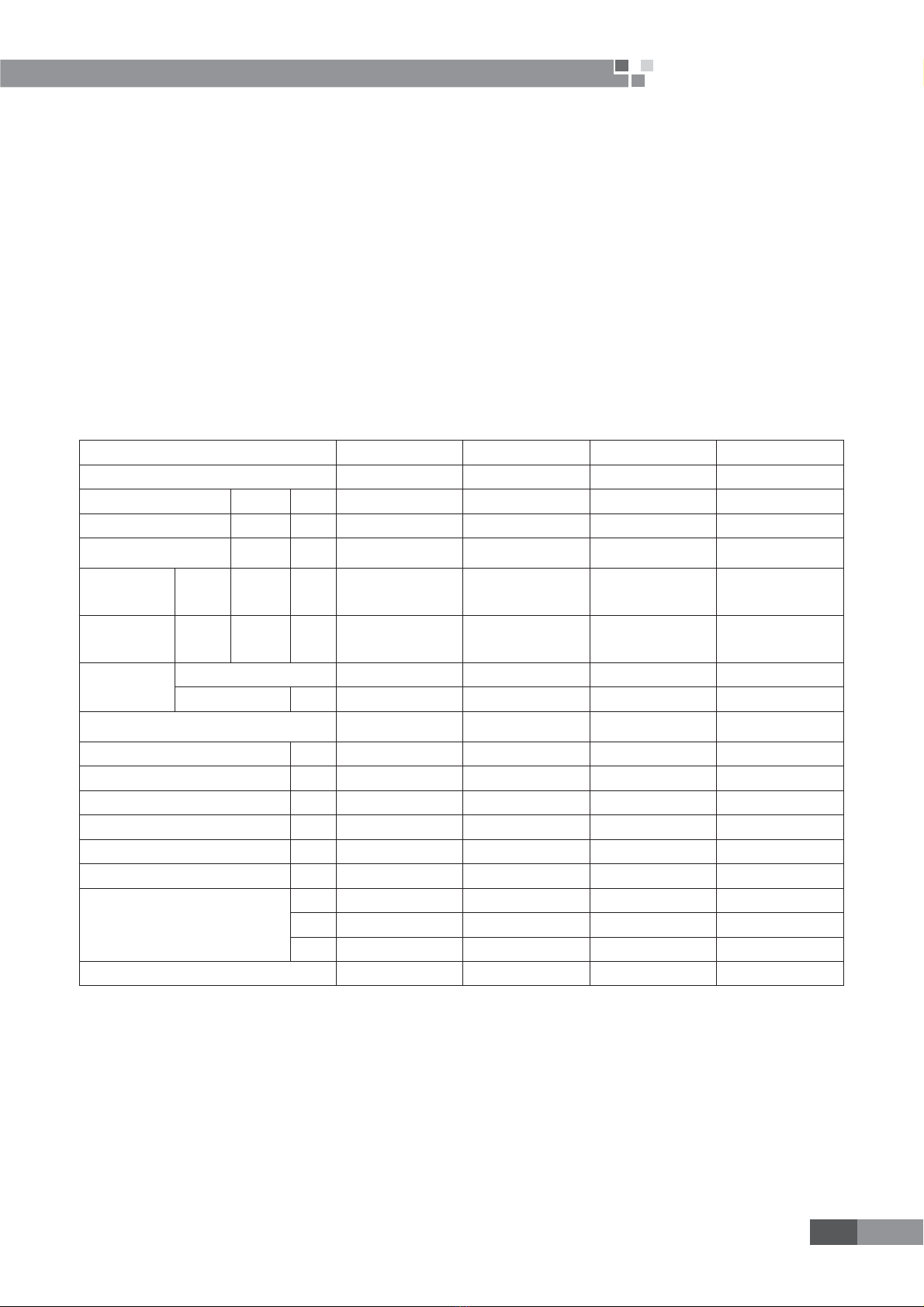
4.1 Product Data at Rated Condition
Model FHBQ-D3.5-K FHBQ-D5-K FHBQ-D8-K FHBQ-D10-K
Code EH01100010 EH01100020 EH01100030 EH01100040
$LUÀRZ9ROXPH H-M-L m3/h 360-260-210 500-380-300 800-600-480 1000-750-600
External Statics Pressure H-M-L Pa 100-80-60 100-80-60 110-85-65 110-85-65
Temperature
H[FKDQJHHI¿FLHQF\ H-M-L % 71-73-75 68-70-72 70-72-74 75-77-79
Enthalpy
exchange
HI¿FLHQF\
Heating H-M-L % 65-67-68 62-64-65 63-65-67 66-68-70
Enthalpy
exchange
HI¿FLHQF\
Cooling H-M-L % 61-63-65 57-59-61 60-62-64 62-64-65
Recommended
wiring
Quantity 3 3 3 3
Area mm21.0 1.0 1.0 1.0
Power Supply 220~240V~1Ph-
50Hz
220~240V~1Ph-
50Hz
220~240V~1Ph-
50Hz
220~240V~1Ph-
50Hz
Power Input W 165 262 400 440
Sound Pressure level dB(A) 37 39 45 46
Outline Dimension (W X D X H) mm 800X879X306 800X879X306 832X1016X380 832X1016X380
Package Dimension (WX D X H) mm 1050X1165X315 1050X1165X315 1087X1320X400 1087X1320X400
Net. Weight kg 45 45 57 57
*URVVZHLJKW kg 53 53 66.5 66.5
/RDGLQJTXDQWLW\
*3 63 63 40 40
*3 147 147 85 59
40'HQ 168 168 104 67
Standard wired remote controller Z5N15 Z5N15 Z5N15 Z5N15

4
Energy-Recovery Ventilation
System Service Manual
QSPEVDU
Model FHBQ-D15-M FHBQ-D20-M FHBQ-D30-M
Code EH01100050 EH01100060 EH01100070
$LUÀRZ9ROXPH H-M-L m3/h 1500 2000 3000
External Statics Pressure H-M-L Pa 150 150 220
Temperature
H[FKDQJHHI¿FLHQF\ H-M-L % 73 71 70
Enthalpy
exchange
HI¿FLHQF\
Heating H-M-L % 65 62 62
Enthalpy
exchange
HI¿FLHQF\
Cooling H-M-L % 60 58 58
Recommended
wiring
Quantity 5 5 5
Area mm21.5 1.5 1.5
Power Supply 380~415V 3N~50Hz 380~415V 3N~50Hz 380~415V 3N~50Hz
Power Input W 600 950 2800
Sound Pressure level dB(A) 48 50 54
Outline Dimension (W X D X H) mm 1210X1215X452 1210X1215X452 1340X1550X572
Package Dimension (WX D X H) mm 1550X1540X470 1550X1540X470 1710X1610X700
Net. Weight kg 100 100 240
*URVVZHLJKW kg 115 115 280
/RDGLQJTXDQWLW\
*3 15 15 9
*3 37 37 24
40'HQ 44 44 24
Standard wired remote controller Z5N15 Z5N15 N/A
Note:
1. The models of 220v power supply type has 3types of fan speed and the models of 380V have one fan
speed.
2. 7KHWHPSHUDWXUHH[FKDQJHHI¿FLHQF\DQGHQWKDOS\H[FKDQJHHI¿FLHQF\DUHWHVWHGXQGHUWKHVHWHVWLQJ
conditions as below:
&RROLQJHI¿FLHQF\,QGRRUDLUćDB, 19.5ćWB, outdoor temperature 35ćDB, 28ćWB.
+HDWLQJHI¿FLHQF\ćDB,13ćWB. Outdoor air temperature: 5 ćDB, 2ćWB.
3. Sound power level according to ISO 5151-sound pressure calculated at 1.5m distance.
4. Operation condition:ambient temperature-15ć-50ć
relevate humidity less than 80ˁRH.

5
Energy-Recovery Ventilation
System Service Manual
QSPEVDU
4.2 Electrical Data
Model
Power
Supply
Fan
Motor
Max. Fuse
Breaker Size
Min.
Disconnect Size
V,Ph,Hz FLA Each Amperes Amperes
FHBQ-D3.5-K
220V~50Hz
0.76A×2 2.47A 1.71A
FHBQ-D5-K 0.76A×2 2.47A 1.71A
FHBQ-D8-K 1.0A×2 3.25A 2.25A
FHBQ-D10-K 1.0A×2 3.25A 2.25A
FHBQ-D15-M
380V 3N~50Hz
1.4A×2 4.55A 3.15A
FHBQ-D20-M 1.4A×2 4.55A 3.15A
FHBQ-D30-M 4.2A×2 13.65A 9.45A
Notes:
1. RLA:Rated load amperes .
2. LRA:Locked rotor amperes .
3. FLA:Full load current .
5 PIPING DIAGRAM
Fresh air
Outdoor
Air discharge
Heat
exchanger
Indoor
Air supply
Room air

6
Energy-Recovery Ventilation
System Service Manual
CONTROL
DPOUSPM

7
Energy-Recovery Ventilation
System Service Manual
DPOUSPM
CONTROL
1 OPERATION FLOWCHART
Initialize
1
Judge running
mode?
By Pass mode
Heat Exchange
mode
Auto mode
N
Y
Y
Y
Y
N
N
Y
N
Y
N
Bengin
L0 Error
Energy-saving function on Energy-saving on
Timer on
Timer function on
Cleaning
Humidifying function on? Stop or move according to the opposite
humidity, Humidity sensor error display L 1
Remind until the time setting come
Air valve interface with electricity?
Air valve
checked OK

8
Energy-Recovery Ventilation
System Service Manual
DPOUSPM
2 MAIN LOGIC
2.1 Auto mode
Detect the temperature indoor and outdoor for durative a period of time.
1. The system will operate under by pass mode according to temperature and temperature difference
between room and outdoors is little in transient season.
7KHV\VWHPZLOORSHUDWHDVVXFKUHTXHVW
By Pass air valve opens, the air discharge fan and air supply fan will operate according to setting fan
speed.
2. The system will operate under heat exchange mode according to temperature and temperature
difference between room and outdoors is large in transient season.
7KHV\VWHPZLOORSHUDWHDVVXFKUHTXHVW
By Pass air valve closes, the air discharge fan and air supply fan will operate according to setting fan
speed.
3. The system will operate according to the primary mode before the system was off.
2.2 By Pass mode
1. Under By pass mode, air valve is open.
2. 7KHV\VWHPZLOORSHUDWHDVVXFKUHTXHVW
If the air valve is close, the air discharge fan and air supply fan will stop. When the air valve is open , the
fan will operate according to setting fan speed .
2.3 Heat Exchange mode
1. Under Heat Exchange mode, the air valve is close
2. 7KHV\VWHPZLOORSHUDWHDVVXFKUHTXHVW
Electrify the air valve motor, judge the position of the air valve. The air discharge fan and air supply fan will
stop if the air valve is open, or they will operate according to setting fan speed .

9
Energy-Recovery Ventilation
System Service Manual
DPOUSPM
3 WIRED REMOTE CONTROLLER
3.1 Operation View
Fig.1 Front panel of wired controller
Constitution of wired controller
1 Timer display 9 &OHDQLQJVWDWXVRI¿OWHUGLVSOD\
2 Energy-saving status display 10 Mode button
3 Setting humidity display 11 Setting humidity increase button
4 Ambient humidity display 12 Setting humidity decrease button
5Air exchange mode (half-half air
exchange ,discharge and supply) 13 Fan speed button
6 Fan speed display (high, mid, low) 14 Reset/Switch button
7Mode(auto, by-pass,
heat exchange) 15 Timer button
8 Error status display 16 On/Off button
1) Turn On / Off the Unit
1. Press ON/OFF button to start the unit. (Fig.2)
2. Press ON/OFF button once again to stop the unit.
Fig.2

10
Energy-Recovery Ventilation
System Service Manual
DPOUSPM
)DQ6SHHG&RQWURO)LJ7KH¿JXUHLVDERXWUHODWLYHGLVSOD\DUHDWKHVDPHDVEHORZ
1. During half-half air exchange, With each press of FAN button, the fan speed will change in the following
order(Fig.3):
Fig.3
2. During air discharge and air supply, with each press of FAN button, the fan speed with switch between
high speed and low peed(Fig.4).
Low High
Fig.4
3) Humidity Adjustment (Fig.5)
If there is humidifying function in the unit, press humidify button:
Ÿ: Used to increase setting humidity.
ź8VHGWRGHFUHDVHVHWWLQJKXPLGLW\
Once press of this button, the temperature will increase or decrease by 5%.
Fig.5
1RWH/RFNIXQFWLRQ3UHVVLQJŸDQGźVLPXOWDQHRXVO\IRUVWKHSODFHRIVHWWLQJKXPLGLW\ZLOOGLVSOD\EE

11
Energy-Recovery Ventilation
System Service Manual
DPOUSPM
DQGDOOUHVSRQVHWRWKHEXWWRQV)LJZLOOEHVKLHOGHG$QGWKHQSUHVVŸDQGźVLPXOWDQHRXVO\IRUVWRUHOHDVH
Lock Function.
When long-distance monitoring or centralized control shield displayed, the signals of buttons and from
remote controller will be shielded, and CC will be displayed in the place of setting humidity.
Setting range of humidity: 40%~60%RH.
4) Reset/ Switch Function Setting ( Fig.6)
Not having pressed Timer button, long press Reset/ Switch button for 5s to clear operation time and icon.
ƇAfter pressing of Timer button:
Under On status of the unit:
Short press Reset/ Switch button to switch among Timer off setting, Energy saving startup setting,Energy
saving stop setting and Clear time setting.
Fig.6
5) Running Mode Setting (Fig.7)
1. Each press of this button, the operation mode will change as follow,
2. Under Auto mode, the letter of Auto will light, so the system will operate according to temperature
and temperature difference between room and outdoors.
3. Under By pass mode, the letter of By Pass will light, so the fan will operate according to setting Fan
mode and fan speed. Make this mode operate in transient season to prolong service life of the core of heat
exchanger.
4. Under Heat Exchange mode, the letter of Heat Exchangewill light. After shutdown of air valve, the
fan will operate according to setting fan mode and fan speed. Under this mode, the total heat exchange of
temperature and humidity can be realized along with exchange of fresh air, which is energy saving and healthy.

12
Energy-Recovery Ventilation
System Service Manual
DPOUSPM
Fig.7
6) Timer Setting(Fig.8)
1. In off status of the unit, timer on can be set and in on status, timer off, energy-saving on and energy –
saving off and air clear can be set.
2. Press Timer button into timer setting status. TIMER,Hr and letters corresponding setting will blink.
3. (JGXULQJWLPHURIIVHWWLQJ7LPHU+UDQG2))ZLOOIODVK,QWKLVFDVHWKHXVHUFDQSUHVVŸRUźWR
increase or decrease setting time. Repress Timer button to make the timer valid and the timing will be Fig.9
calculated after that. When the unit is under timer state, press theTimer button to cancel it. The time interval is
0.5 hr.
4. The setting range of Timer on/off is 0.5-24hr.
5. The setting range of Energy Saving On is 2-5hr and the default is 2hr.
6. 7KHVHWWLQJUDQJHRI(QHUJ\6DYLQJ2IILVKUDQGWKHGHIDXOWLVKU1RWHSUHVV)$1DQGźDWWKH
same time for 5s only after energy saving timer setting, the energy saving function can operate.
7. The setting range of Timer Clear is 1250hr, 2500hr and 00000.The default is 1250hr.
Fig.8
7) Ambient Temp Display
Under normal state, only indoor ambient humidity is display at ENV.
Notice: The humidifying function with the unit can be valid after it is started.
8) Humidifying ON/OFF Display
3UHVV02'(DQGźDWWKHVDPHWLPHIRUVWRVZLWFKEHWZHHQKXPLGLI\LQJ212))
Note:The unit with humidifying function can normally run. The indoor humidity and setting humidity can be
GLVSOD\HGRQO\,IWKLVIXQFWLRQLVRQ7KHGHIDXOWLV2)),WLVUHFRPPHQGHGWR21LQGU\SHULRG7KH¿WWLQJVDUH
optional.

13
Energy-Recovery Ventilation
System Service Manual
DPOUSPM
9) Fan Mode Display
3UHVV)$1DQGŸDWWKHVDPHWLPHIRUVWRVZLWFKDPRQJKDOIKDOIDLUH[FKDQJHGLVFKDUJHDQGVXSSO\
Refer to Fig.2 for details. The fan mode is selected by the users. E.g. plus pressure is needed in the room, fan
mode can be adopted and if negative pressure is needed, air discharge mode can be adopted. Half-half air
exchange is for normal station.
10) Energy Saving Mode Display
3UHVV)$1DQGźDWWKHVDPHWLPHIRUVWRVZLWFKEHWZHHQHQHUJ\VDYLQJRQRII,IXQGHUHQHUJ\VDYLQJ
on state, Energy Saving will be displayed. Refer to Fig.2 for details. If the unit needn’t operate for a long time,
HQHUJ\VDYLQJPRGHFDQEHDGRSWHGWRPHHWWKHGHPDQGVRIERWKIXQFWLRQRIIUHVKDLUH[FKDQJHDQGTXDOLW\RI
indoor air by users.
3.3 Dimension
Panel Dimension and Installation Dimension

14
Energy-Recovery Ventilation
System Service Manual
DPOUSPM
Bottom Panel Dimension and Installation Dimension
3.4 Installation
1. Locate the installation position firstly, and then reserve a groove or hole for embedding of
communication wire according to its dimension.
2. If wired controller and indoor communication wire are mounted visibly, 1 ʿPVC pipe can be used and
corresponding grooves should be set in the wall. If in hidden, 1 ʿPVC pipe can be used.
3. Whether mounted visibly or in hidden, drill two holes (keep level) in the wall as the distance (60mm)
between the two holes in underplate of wired controller, and then inset stopper into the holes through which the
ZLUHGFRQWUROOHUFDQEH¿[HG,QVHUWFRPPXQLFDWLRQZLUHLQWKHFRQWUROERDUG$WODVWFODVSWKHFRQWUROOHUSDQHO
Note: During installation of underplate of wired controller, pay attention to its direction. The side with 2
breaches must be kept downwards.
PVC pipe
No. Name Remarks

15
Energy-Recovery Ventilation
System Service Manual
DPOUSPM
1 Wall
The appearance of the controller
should be subject to entity.
2 Underplate of wire controller
3 Screw M4X10
4 Controller panel
We must not tear down the panel in these wrong ways as:
From
above From
below
From
right
From
left
When you want to check the panel ,you need use a screwdriver to tear down it like this:

16
Energy-Recovery Ventilation
System Service Manual
Screwdriver
ķ
ĸ Ĺ
ĺ Ļ
Display board and Bottom panel are
separate absolutely.
Clip button
Circumrotate the screwdriver
clockwise or anticlockwise, the
same to the other side.
Pull the display board
to make the clip break
off.
ļ
Insert this position with
a screwdriver

17
Energy-Recovery Ventilation
System Service Manual
INSTALLATION

18
Energy-Recovery Ventilation
System Service Manual
INSTALLATION
1 DIMENSION DATA
Fresh air
outlet
Room air
inlet
Fresh
air intlet
Room air
outlet
Uint: mm
Model A A1 B B1 C C1 D E F *HN
FHBQ-D3.5-K 879 823 800 852 306 125 90 125 175 136 416 197
FHBQ-D5-K 879 823 800 852 306 125 90 125 175 136 416 197
FHBQ-D8-K 1016 960 832 884 380 165 90 150 230 155 372 246
FHBQ-D10-K 1016 960 832 884 380 165 90 150 230 155 372 246
FHBQ-D15-M 1215 1159 1210 1262 452 200 100 190 277 178 737 297
FHBQ-D20-M 1215 1159 1210 1262 452 200 100 190 277 178 737 297
WL
W2
B2
B1
B
W1
fresh air inlet
room air inlet
room air outlet
L1
electric
box
H
H1
A2
A
A3
A1
flange dimention
fresh air outlet
Uint: mm
Model L L1 W W1 W2 H H1 A A1 A2 A3 B B1 B2
FHBQ-D30-M 1550 1650 1340 1310 670 572 249 346 386 180 366 332 372 352
This manual suits for next models
6
Table of contents
Other Gree Fan manuals