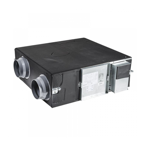
Gree FHBQGL-D1.5DA-T User manual

Owner's Manual
Original Instructions
Energy Recovery Ventilation System
Models:
FHBQGL-D1.5DA-T
FHBQGL-D2.5DA-T
FHBQGL-D3.5DA-T
FHBQGL-D5DA-T

To Users
Thank you for selecting Gree product. Please read this instruction manual
carefully before installing and using the product, so as to master and correctly use
the product. In order to guide you to correctly install and use our product and
achieve expected operating effect, we hereby instruct as below:
(1) This appliance is not intended for use by persons (including children) with
reduced physical, sensory or mental capabilities, or lack of experience
and knowledge, unless they have been given supervision or instruction
concerning use of the appliance by a person responsibility for their safety.
Children should be supervised to ensure that they do not play with the
appliance.
(2) In order to ensure reliability of product, the product may consume some
power under stand-by status for maintaining normal communication of
system and preheating refrigerant and lubricant. If the product is not to
be used for long, cut off the power supply; please energize and preheat
the unit in advance before reusing it.
(3) Please properly select the model according to actual using environment,
otherwise it may impact the using convenience.
(4) If the product needs to be installed, moved or maintained, please contact
our designated dealer or local service center for professional support.
Users should not disassemble or maintain the unit by themselves,
otherwise it may cause relative damage, and our company will bear no
responsibilities.
(5) All the illustrations and information in the instruction manual are only for
reference. In order to make the product better, we will continuously
conduct improvement and innovation. If there is adjustment in the
product, please subject to actual product.

Exception Clauses
Manufacturer will bear no responsibilities when personal injury or property loss
is caused by the following reasons:
(1) Damage the product due to improper use or misuse of the product.
(2) Alter, change, maintain or use the product with other equipment without
abiding by the instruction manual of manufacturer.
(3) After verification, the defect of product is directly caused by corrosive
gas.
(4) After verification, defects are due to improper operation during
transportation of product.
(5) Operate, repair, maintain the unit without abiding by instruction manual or
related regulations.
(6) After verification, the problem or dispute is caused by the quality
specification or performance of parts and components that produced by
other manufacturers.
(7) The damage is caused by natural calamities, bad using environment or
force majeure.

Contents
1 Safety Notices (Please be Sure to Abide)·····················1
2 Product Introduction·················································4
2.1 Main Unit Structure······················································ 6
2.2 Outline Dimension ······················································· 7
2.3 Product Performance Parameter ···································· 8
2.4 Accessory List ···························································· 9
3 Installation·······························································9
3.1 General Instruction ······················································ 9
3.2 Engineering Design ····················································· 9
4 Electric Installation·················································16
4.1 Unit External Wiring Diagram ······································· 16
4.2 Electric Installation Demands ······································· 16
4.3 Grounding Demands ·················································· 17
4.4 Wring Demands ························································ 18
4.5 Demands for Selecting Communication Wire ··················· 18
4.6 Wiring Work ····························································· 20
5 Operation and Maintenance·····································24
5.1 Check before Running Test ········································· 25
5.2 Running Test ···························································· 25
5.3 Daily Maintenance····················································· 25
5.4 Table of Error Codes ·················································· 26

Energy Recovery Ventilation System
1
1 Safety Notices (Please be Sure to Abide)
WARNING! If not abide strictly, it may cause severe damage to the unit or
the people.
NOTE! If not abide strictly, it may cause slight or medium damage to the
unit or the people.
This sign indicates that the operation must be prohibited. Improper
operation may cause severe damage or death to people.
This sign indicates that the items must be observed. Improper operation
may cause damage to people or property.
WARNING!
This product can’t be installed at corrosive, inflammable or explosive
environment or the place with special requirements, such as kitchen. Otherwise, it
will affect the normal operation or shorten the service life of the unit, or even cause
fire hazard or serious injury. As for above special places, please adopt special air
conditioner with anti-corrosive or anti-explosion function.
Follow this instruction to
complete the installation
work. Please carefully
read this manual before
unit startup and service.
Installation should be
conducted by dealer or
qualified personnel.
Please do not attempt to
install the unit by
yourself. Improper
handling may result in
water leakage, electric
shock or fire disaster
etc.
Before installation,
please check if the power
supply is in accordance
with the requirements
specified on the
nameplate. And also take
care of the power safety.
Make sure the unit can
be earthed properly and
soundly after plugging
into the socket so as to
avoid electric shock.
Please do not connect
the ground wire to gas
pipe, water pipe,
lightning rod or
telephone line.

Energy Recovery Ventilation System
2
Be sure to use the
exclusive accessory and
part to prevent the water
leakage, electric shock
and fire accidents.
Wire size of power cord
should be large enough.
The damaged power
cord and connection
wire should be replaced
by exclusive cable.
After connecting the
power cord, please fix
the electric box cover
properly in order to avoid
accident.
Do not expose the unit
to the moist or corrosive
circumstances.
Never start up or shut off
the unit by means of
directly plug or unplug
the power cord.
Please firstly connect
the wired controller
before energization,
otherwise wired
controller cannot be
used.
Do not allow children
operate this unit. Do not operate this unit
with wet hands.
Never spray or flush
water towards unit;
Otherwise, malfunction
or electric shock may
happen.
Once installation is
finished, please check if
the connection of power
cord and
communication line are
correct to avoid electric
shock, short circuit, fire
hazard and other
accidents.
Turn off the unit or cut off
the power supply before
cleaning the unit,
otherwise electric shock
or injury may happen.
Do not insert fingers or
objects into air
outlet/inlet grille.

Energy Recovery Ventilation System
3
Volatile liquid, such as
diluent or gas will
damage the unit
appearance. Only use
soft cloth with a little
neutral detergent to
clean the outer casing of
unit.
User is not allowed to
repair the unit. Fault
service may cause
electric shock or fire
accidents. Please
contact Gree appointed
service center for help.
For nonprofessionals,
never touch the fan
volute or other movable
parts, as it may result in
injury.
Please cut off the power
supply when this unit is
not used for a long time
in consideration of
safety.
Please clean the filter
periodically to keep it
clean.
Install a bird screen or a
similar device at the
external air vent.
Outdoor air inlet should
be installed at the
position where is far
away from the discharge
outlet of inflammable
gas.
The air inlet should be
installed at the position
where the air won’t flow
back directly.
Reserve the service port
according to the
dimension indicated by
the installation
instruction.
In order to avoid
incomplete combustion,
which may lead to
intoxication, keep
heating appliances
away f
rom the air flow of
the unit.
As for pipe fan and wall
fan, please note that the
gas must be flow back to
indoors from the open air
way or other fire
equipment.
Please make sure that it
can be used in
special-purpose places
(such as the places
where there are
precision instruments,
food or fine arts).

Energy Recovery Ventilation System
4
If anything abnormal
happens (such as
burning smell), please
power off the unit and cut
off the main power
supply, and then
immediately contact
Gree appointed service
center. If abnormality
keeps going, the unit
might be damaged and
lead to electric shock or
fire.
Due to the limitation of
the detection principle of
the air quality testing
instrument, the air
quality testing
instrument will inevitably
have different deviation
for the places where
there are humidifier and
aromatherapy machine.
The actual performance
of the unit is normal.
Please feel free to use
it.
2 Product Introduction
Energy recovery ventilation system is a kind of device that purifies and precools
or preheats outdoor fresh air. The unit is equipped with filters and a set of
high-efficiency energy recovery cores. When the fan is running, outdoor fresh air
and indoor discharged air enter into the unit along the ducts through outdoor air inlet
port and indoor air discharge port. Outdoor fresh air and indoor discharged air are
filtrated through filters inside the unit. The purified outdoor fresh air is sent to the
indoors after sufficient heat and humidity exchange with indoor discharged air in
energy recovery cores, so as to reduce the load of fresh air to achieve energy
saving.
The unit adopts DC motor and constant air volume control technology to
maintain fresh air volume constant when the filter is dirty in a certain degree. The
unit structure design is flexible with lower maintenance way, so that the
maintenance of filter and motor is simple. Internal unit adopts inner insulation
design, to prevent condensation in summer and winter, as well as reducing noise.
The product accords with Rule (EU) 1253–2014、(EU) 1254–2014.

Energy Recovery Ventilation System
5
Table1 Function List
Function
Model
Remark
FHBQGL-D1.5DA-T
FHBQGL-D2.5DA-T
FHBQGL-D3.5DA-T
FHBQGL-D5DA-T
Operation control
√
—
Linkage control ○
This function is available when the unit is
operating with Gree VRF system
Auto control ○
This function is available when the unit is
operating with Gree air box
Fan speed
√
—
Heat recovery operation mode
√
—
Bypass operation mode
√
—
Discharge operation mode
√
—
Positive and negative pressure
mode
√ —
Air quality detection ○
This function is available when the unit is
operating with Gree air box
Dehaze
√
—
Filter cleaning/replacing
reminder √ —
Timer
√
—
Group control ○
This function is available when the unit is
operating with Gree VRF system or virtual
outdoor unit
Slave wired controller
○
—
Centralized control ○
This function is available when the unit is
operating with Gree centralized controller
Long-distance control ○
This function is available when the unit is
operating with Gree long-distance
monitoring system
Lock
√
—
Shield
√
—
Memory
√
—
Auxiliary heating
×
—
Healthy
×
—
Humidification
×
—
Dehumidification
×
—
Remark: √-Standard function, ○-Optional function, ×-Not available.

Energy Recovery Ventilation System
6
2.1 Main Unit Structure
Main structure diagram of main unit is as below.
No.
Name
No.
Name
1
Exhaust air outlet port
9
Clasp
2
Extract air inlet port
10
Outdoor air filter
3
Outdoor air inlet port
11
Energy recovery core
4
Supply air outlet port
12
Extract air filter
5
Limiting sheet of maintenance panel
13
Filter damper
6
Maintenance panel 1
14
Electric box
7
Maintenance panel 2
15
Limiting sheet of core
8
Hook
16
Filter damper

Energy Recovery Ventilation System
7
2.2 Outline Dimension
①
②
③
Fig.1 Outline Dimension

Energy Recovery Ventilation System
8
Fig② is the front view of maintenance panel of FHBQGL-D3.5DA-T and
FHBQGL-D5DA-T;
Fig③ is the front view of maintenance panel of FHBQGL-D1.5DA-T and
FHBQGL-D2.5DA-T.
Table2 Outline Dimension
Unit: mm
Model
A
B
C
D
E
F
FHBQGL-D1.5DA-T
1326
1160
220
1000
700
318
FHBQGL-D2.5DA-T
1326
1160
220
1000
700
318
FHBQGL-D3.5DA-T
1366
1200
240
897
785
424
FHBQGL-D5DA-T
1584
1385
240
1203
785
383
Model
G
H
I
J
K
L
M
FHBQGL-D1.5DA-T
311
740
636
150
470
216
388
FHBQGL-D2.5DA-T
311
740
636
150
470
216
388
FHBQGL-D3.5DA-T
377
825
650
150
555
277
343
FHBQGL-D5DA-T
366
825
653
185
555
248
375
2.3 Product Performance Parameter
Table3 Performance Parameters
Model Power
supply
Power
(W)
Air
volume
(m3/h)
External
static
pressure
(Pa)
Sound
power
level
(dB)
Thermal
efficienc
y(nomin
al flow
rate )
Thermal
efficienc
y(referen
ce flow
rate)
Net
weight
(kg)
FHBQGL-D
1.5DA-T
208-230V
~,60Hz;
220-240V
~,50Hz
50 150 100 43 80% 90% 50
FHBQGL-D
2.5DA-T
105 250 100 50 75% 79% 50
FHBQGL-D
3.5DA-T
155 350 100 55 76% — 60
FHBQGL-D
5DA-T
250 500 100 57 73% — 71.5
NOTES!
① Sound power level noise is tested in semi-anechoic room according to
related test method specified in standard EN ISO 3744. Actual noise
may be various due to actual environment influence.

Energy Recovery Ventilation System
9
② Thermal efficiency is tested according to related test method and
temperature condition specified in standard EN 13141-7:2010. Actual
thermal efficiency may be various due to actual temperature condition.
③ Specifications may be changed due to product improvement. Please
refer to nameplates of the units.
④ The nominal static pressure is the static pressure tested acquiescently
when leaving the factory, other high-level filter might affect unit
performance parameter.
2.4 Accessory List
Table4 Accessory list
Unit: pc
Model Wired
controller
Nut M10
with washer Nut M10 Flat washer
10
Spring washer
10
FHBQGL-D1.5DA-T
1
4
4
4
4
FHBQGL-D2.5DA-T 1 4 4 4 4
FHBQGL-D3.5DA-T 1 4 4 4 4
FHBQGL-D5DA-T 1 4 4 4 4
NOTE! The package carbon of unit can be used for locating the unit during
installation.
3 Installation
3.1 General Instruction
User should consign the model selection and engineering design to
professional HVAC engineers and employ experienced constructor to complete the
construction. The design and construction should be in accordance with relevant
national norms, regulations.
3.2 Engineering Design
PVC ducts for outdoor air inlet and indoor air supply shall be equipped by the
user. As the unit adopts DC motor, air volume can keep constant in a certain system
resistance range. If system resistance exceeds this range, air volume will be lower

Energy Recovery Ventilation System
10
as resistance gets bigger. When the air flow goes through the ducts, the ducts will
generate resistance to the air flow. If the duct length is too long, duct diameter is too
small and elbows are too many, air resistance in the duct will increase and air
volume will be decreased. To avoid performance degradation, please follow the
following recommended principles for installation and design:
(1) The total length of air inlet duct and air return duct shall be designed
according to the characteristics of the site. The resistance of the air duct
shall not exceed the static pressure requirement of the unit. The air duct
should be made of nonflammable or non-combustible materials.
(2) Elbow shall be set as little as possible. Elbow quantity in each duct line
shall be within 3. The bent part of elbow should be designed as a circular
arc, avoiding a 90° right-angle bend.
(3) Try to avoid using it if the resistance difference of pipeline at both sides
of air outlet of fresh air unit is big.
(4) The outer wall of the ducts connected to the outdoor side (fresh air inlet
duct and discharged air outlet duct) should be insulated; the installation
should be inclined to the outdoors with a slope of 1/100~1/50 to prevent
rainwater intrusion.
Fig.2 Installation Diagram of Outdoor Connection Duct
(5) The internal wall of duct shall be smooth, not afford to dust and not
folded. Outdoor air inlet port shall be installed in the area where is
convenient for maintenance.
(6) If the user wants the indoor noise as small as possible, the muffler shall
be applied in the connection joints of air ducts. Please consult with a

Energy Recovery Ventilation System
11
professional as there are many kinds of muffler. When suitable mufflers
are installed, the noise at air outlet port can be reduced by 4~6 dB.
(7) The air filter inside the unit shall be replaced regularly. Therefore, in
design and installation, the maintenance space should be left under the
unit. The dimension of maintenance space is shown as below.
NOTE!
When installing FHBQGL-D1.5DA-T and FHBQGL-D2.5DA-T in ceiling,
maintenance panel 1 and maintenance panel 2 should be completely exposed to
the maintenance port, so that the user can remove the maintenance panel 2 with a
screwdriver.
Unit: mm
Fig.3 Maintenance Port Illustration

Energy Recovery Ventilation System
12
Unit: mm
Model
A
B
C
D
FHBQGL-D1.5DA-T
600
600
260
80
FHBQGL-D2.5DA-T 600 600 260 80
FHBQGL-D3.5DA-T 600 600 315 80
FHBQGL-D5DA-T 600 600 410 80
(8) The unit shall adopt ceiling installation with installation height of 2.3m
from the floor.
(9) Use expansion bolts for fixing with the ceiling. Installation steps are as
below:
1) Drill 4 holes at the installation position: hole diameter please refer to
the diameter of expansion bolt and the depth is about 60~70mm.
Unit: mm
Fig.4 Sectional View of Drilling Hole
2) Use expansion bolts for fixing with the ceiling. Installation steps are as
below:
NOTE!
The length of bolt can be selected according to installation height. Bolts are
provided by the user.

Energy Recovery Ventilation System
13
Fig.5 Sectional View for Installing Expansion Bolt
3) The unit is installed in the bolts at the ceiling of the room and is fixed
by the nuts provided with other accessories.
Unit: mm
Fig.6 Hanging Frame Placing Diagram
(10) The unit is installed in the bolts at the ceiling of the room and is fixed by
the nuts provided with other accessories.
Unit: mm
Fig.7 Installation Diagram of Hoses

Energy Recovery Ventilation System
14
Installation diagram of the system is as follow:
Fig.8 Installation Diagram of the System
NOTE! Do not put through power until all installation works are done.
Filter and core dimension and replacing time:
Table5 Specification of Filter and Core
Unit: mm
Model
Filter
Energe recovery core
FHBQGL-D1.5DA-T
255×103×28.3
255×204×360
FHBQGL-D2.5DA-T
255×103×28.3
255×204×360
FHBQGL-D3.5DA-T
295×103×28.3
295×204×360
FHBQGL-D5DA-T
295×135×28.3
295×200×400
Recommended reolacing time Cleaning and replacing
reminder by wired controller
2 years
Filter

Energy Recovery Ventilation System
15
Energy Recovery Core
Method for replacing energy recovery core and filter as shown in the figure,
open the limiting sheet of maintenance panel; open the clasp and take off
maintenance panel 1 and 2 (for model FHBQGL-D1.5DA-T and FHBQGL-D2.5DA-T,
remove the fixing screw of maintenance panel 2 with a screwdriver); rotate filter
damper to replace filter; loosen the limiting sheet of core with a screwdriver and pull
away the sheet to replace the energy recovery core.
Fig.9 Filter and Core Replacing Diagram
Method for repairing motor: after main power supply is cut off for 5mins, open
and remove maintenance panel ①, remove energy recovery cores and filters →
remove electric box ②, pull out the motor wiring terminal on the mainboard →
remove filter installation plate ③ → pull out the motor installation plate ④.

Energy Recovery Ventilation System
16
Fig.10 Motor Maintenance Diagram
WARNING!
When the maintenance panel shall be opened during maintenance (e.g. cleaning, replacing filter,
repairing motor and electric box), please remove maintenance panel completely to avoid accidents.
4 Electric Installation
4.1 Unit External Wiring Diagram
External wiring diagram (when it is not corresponding to the electric diagram of
wiring box, please refer to the electric diagram of wiring box).
Fig.11 External Wiring Diagram
4.2 Electric Installation Demands
(1) Install units according to national wiring codes.
(2) Power cord must be reliably secured to avoid stress on wire terminal. Do
not pull the power cord with force.
This manual suits for next models
3
Table of contents
Other Gree Fan manuals
Popular Fan manuals by other brands

Designers Fountain
Designers Fountain 52TB3L5-NI owner's manual

Xpelair
Xpelair C6S Installation and maintenance instructions

WT Knowles & Sons
WT Knowles & Sons KSFM1 Fitting instructions

Somogyi Elektronic
Somogyi Elektronic Home SF41/BK instruction manual

ORIGO
ORIGO CF1532 instruction manual

FUAVE
FUAVE SV7010 manual