8
Energy-Recovery Ventilation
System Service Manual
CONTROL
2 MAIN LOGIC
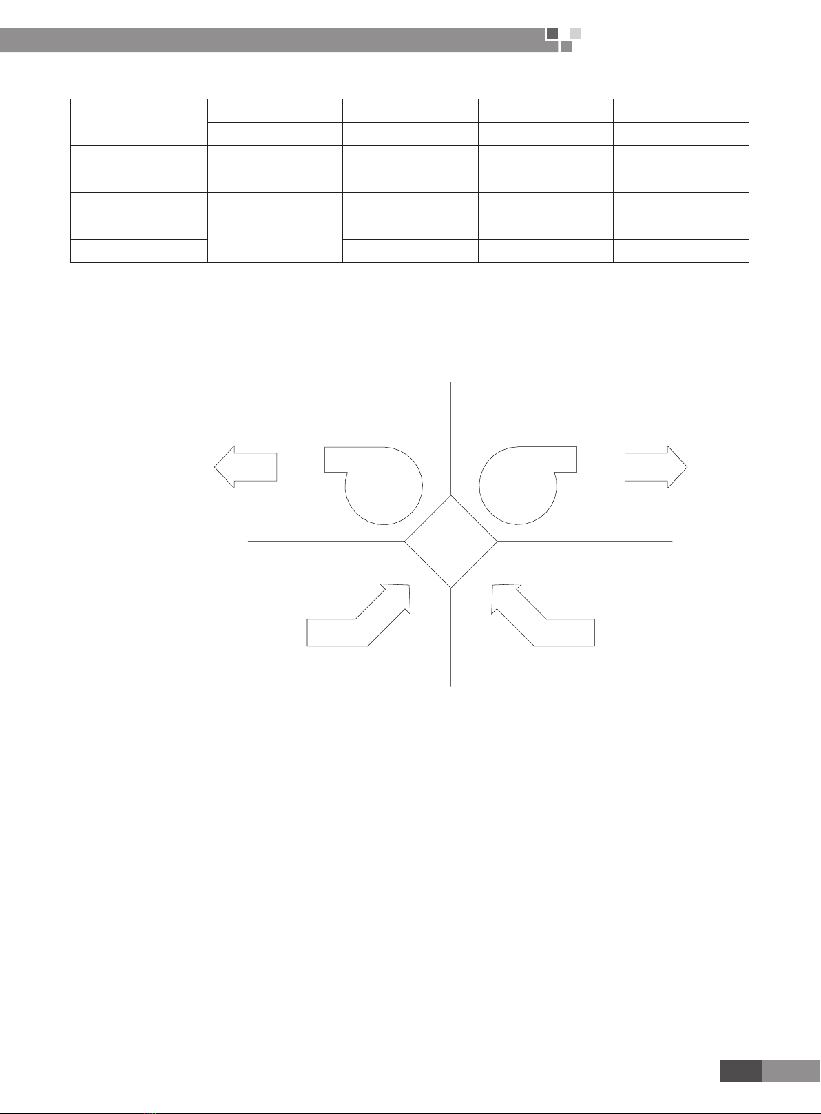
2.1 Auto Mode
Detect the temperature indoor and outdoor for durative a period of time.
(1) The system will operate under by pass mode according to temperature and temperature difference between room and
outdoors is little in transient season.
The system will operate as such request:
By Pass air valve opens, the air discharge fan and air supply fan will operate according to setting fan speed.
(2) The system will operate under heat exchange mode according to temperature and temperature difference between
room and outdoors is large in transient season.
The system will operate as such request:
By Pass air valve closes, the air discharge fan and air supply fan will operate according to setting fan speed.
(3) The system will operate according to the primary mode before the system was off.
2.2 By-pass Mode
(1) Under By pass mode, air valve is open.
(2) The system will operate as such request:
If the air valve is close, the air discharge fan and air supply fan will stop. When the air valve is open , the fan will operate
according to setting fan speed.
2.3 Heat exchange Mode
(1) Under Heat Exchange mode, the air valve is close.
(2) The system will operate as such request:
Electrify the air valve motor, judge the position of the air valve. The air discharge fan and air supply fan will stop if the air
valve is open, or they will operate according to setting fan speed.
3 WIRED REMOTE CONTROLLER
3.1 Operation View
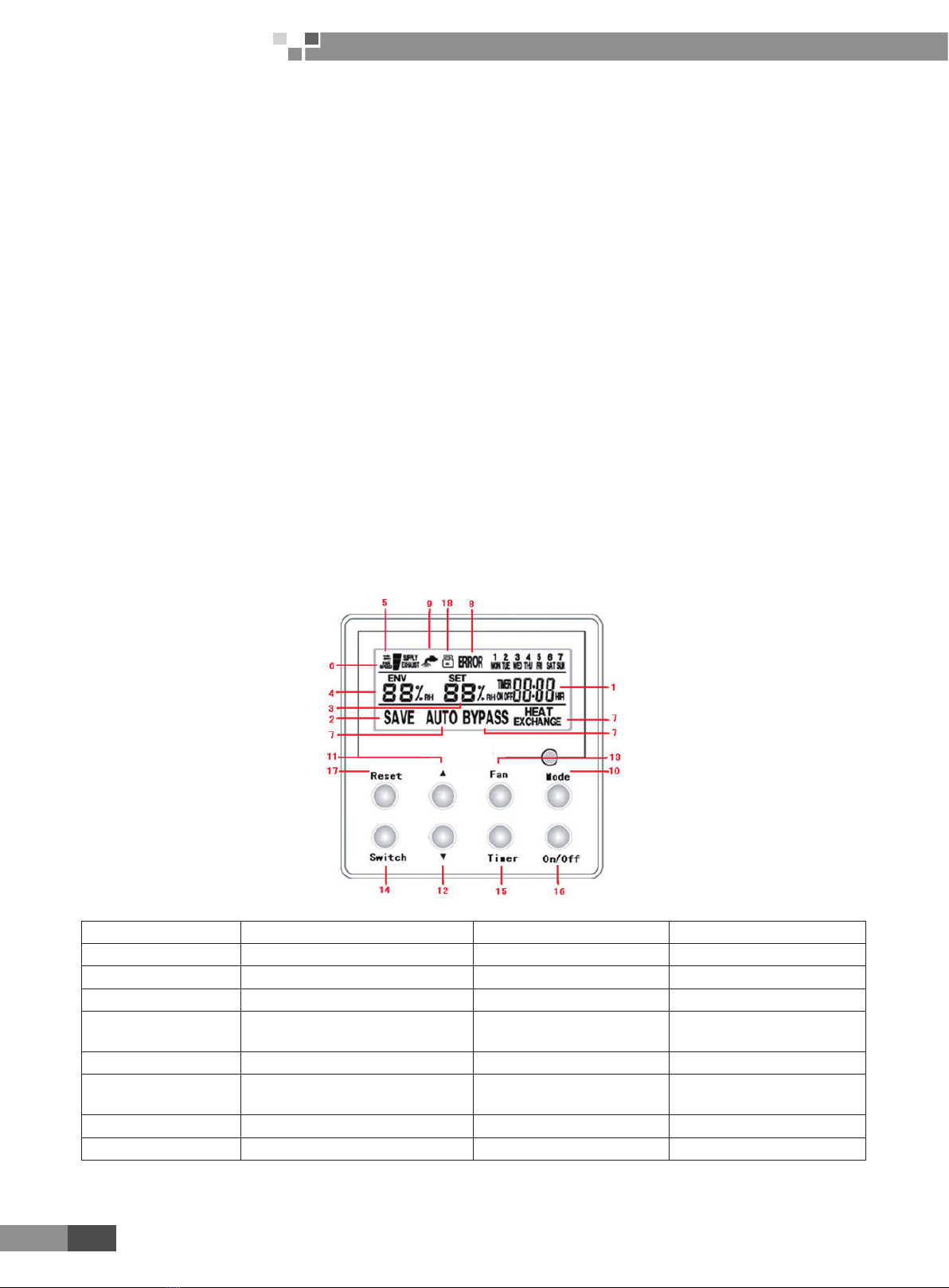
Fig.1 Front panel of wired controller
1 Timing set point 10 Mode key
2 Energy saving status 11 Humidity increasing key
3 Humidity set point 12 Humidity decreasing key
4 Environment temperature 13 Fan speed key
5 Air mode status (fresh air,
discharge air, supply air) 14 Switching key
6 Fan speed status (hi/medium/low) 15 Timing key
7 Mode status (Auto, Bypass,
Heat exchange) 16 On/Off key
8 Error status 17 Reset key
9 Filter cleaning status 18 Child lock icon
Notice: For FHBQ-D15 and FHBQ-D20, there is no discharge air and supply air modes for the item number 5 and fan
speed is uncontrolled for the item number 6.