GREEN BANK XMJ48200 User manual

USER GUIDE
LiFePO4 Battery System for Households
358-010204-01

Contents
1 ABOUT THIS MANUAL .....................................................................................
1.1 Purpose ..................................................................................................
1.2 Scope .....................................................................................................
1.3 Safety Instructions ...................................................................................
1
1
1
1
2 INTRODUCTION .............................................................................................. 2
2.1 Features................................................................................................. 2
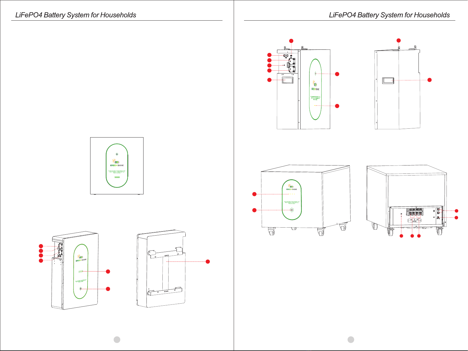
2.2 Product Over View .................................................................................. 2
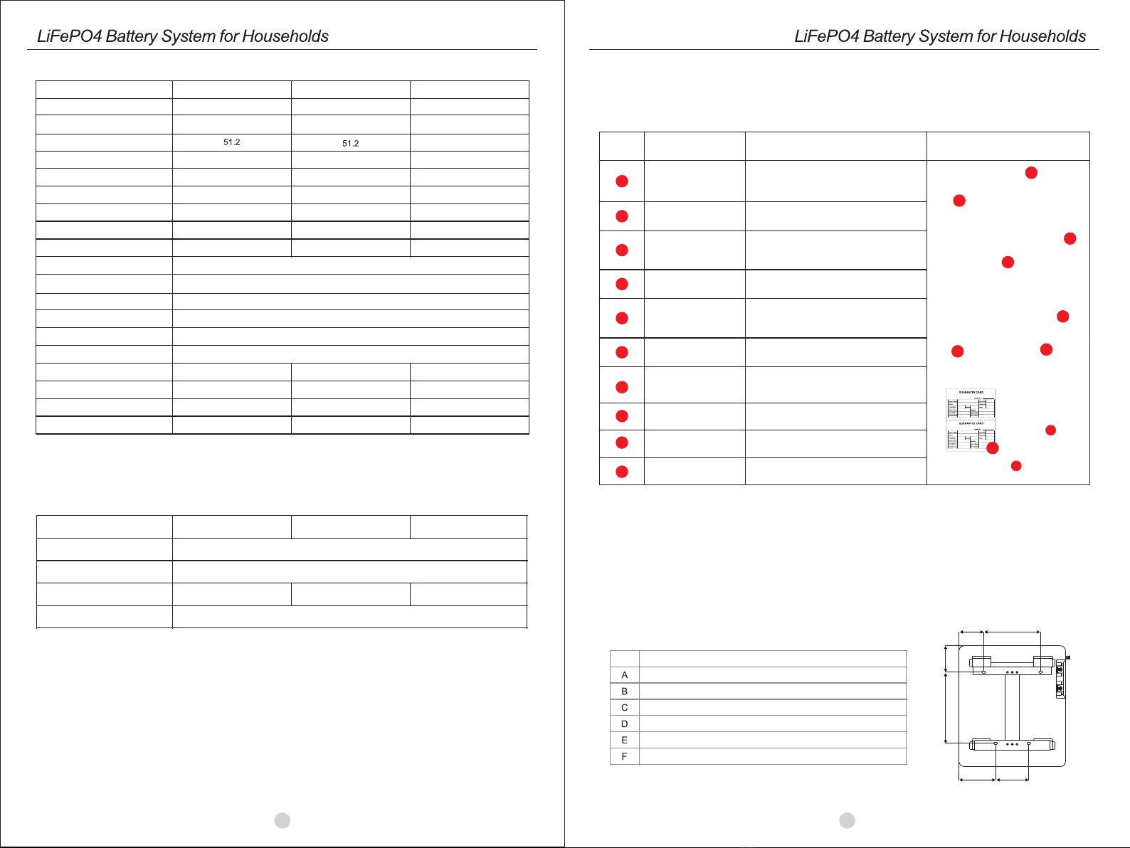
2.3 Specifications ........................................................................................ 4
2.4 Recommended Settings .......................................................................... 4
3. INSTALLATION ................................................................................................ 5
3.1 Unpacking and Inspection ....................................................................... 5
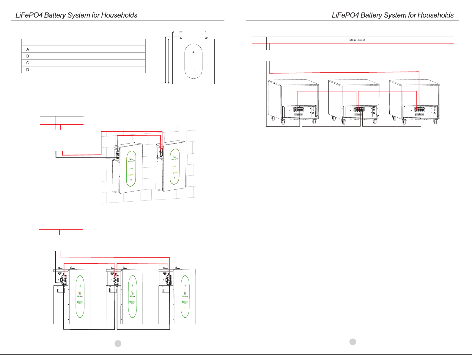
3.2 Mounting the Unit ................................................................ ................... 5
4. OPERATION ................................................................................................... 7
4.1 Switch On/Off........................................................................................... 7
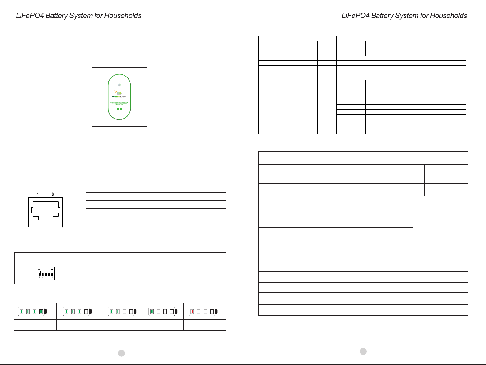
4.2 Description for LED ................................................................................. 7
4.3 ON / OFF or SOC Led (Mode or SOC) ........................................................ 8
3.3 Connection for Parallel Mode ...................................................... ............. 6
5. EMERGENCY SITUATIONS ............................................................................. 9
5.1 Fire .......................................................................................... . . .......... 9
5.2 Leaking Batteries .................................................................... .. .. .. . ....... 9
5.3 Wet Batteries ......................................................................................... 9
5.4 Warranty ............................................................................. . . .. .............. 9
4.4 DIP switch SW1-SW4 Description ............................................................. 8
1.1 Purpose
This manual describes the introduction,installation, operation and emergency situations of the battery bank.
Please read this manual carefully before installations and operations. Keep this manual for future reference.
1.2 Scope
This manual provides safety and installation guidelines as well as information on tools and wiring.
1.3 Safety Instructions
WARNING: This chapter contains important safety and operating instructions. Read and keep this
manual for future reference.
1.Before using the unit, read all instructions and cautionary markings on the unit, the batteries
and all appropriate sections of this manual.
2.CAUTION – ,even burst. please use it following using manual.-- To reduce risk of injury,damage
In case of causing personal
3.Do not disassemble the battery. Take it to a qualified service center when service or repair is
required.Incorrect re-assembly may result in a risk of fire.
4.To reduce risk of electric shock, disconnect all wirings before attempting any maintenance or
cleaning.Turning off the unit will not reduce this risk.
5.CAUTION – Only qualied personnel can install this device with inverter.
6.For optimum operation of this battery, please follow required spec to select appropriate cable size.
7.Be very cautious when working with metal tools on or around batteries. A potential risk exists to drop a tool
to spark or short circuit batteries or other electrical parts and could cause an explosion or fire.
8.Please strictly follow installation procedure.
9.To support full output load, at least 2 sets of XMJ48V for inverter larger than 6KVA in parallel connection.
10.GROUNDING INSTRUCTIONS - This System should be connected to a permanent grounded
wiring system. Be sure to comply with local requirements.
11.NEVER cause AC ou t pu t a n d DC input short circuited. Do not connect to the mains when
DC input short circuits.
12.Warning!! Only qualified service persons are able to service this device.
13.Battery should be installed indoor and kept away from water, high temperature mechanical force and flames.
14.Do not install the battery in any environment of temperature below 0°C or over 55°C,andhumidity over 80%.
15.Do not put any heavy objects on the battery.
01
Special Attention: Due to the built-in protection board of the lithium battery pack is with
over-discharge protection function, it is strongly recommended to stop using the load when
the battery pack is over-discharged. The battery pack cannot be repeatedly activated for
discharge. Therefore, when the battery pack is low power, please charge the battery as
soon as possible when main power or solar energy is available.
1. The batteries can be connected in parallel. Series connection is not allowed.
Use in upright position only.
2. The batteries are not allowed to connected with PWM controller for charging.
1.4 Can be connected in parallel

02
2. INTRODUCTION
The battery system main using Solar power system for Family house.It also have a with to controller the
battery easily and protect our Household application timely.
•Iron phosphate-lithium power battery
•Long warranty period:2 years
•Higher energy density,smaller volumn for household.
•Support connected in parallel mode for expansion
•Photovoltaic system: This battery pack is designed for household photovoltaic systems.
•Battery management system (BMS): The battery packs built-in BMS monitors its
operation and prevents the battery from operating outside design limitations.
•Expandability: This battery pack can be easily expanded by adding expansion battery packs
in parallel connection.
2.2 Product Over View
2.1 Features
03
48V Front view
2
1
6
3
5
4
8
7
10
9
XMJ48200
3
5
1
6
4
8
XMJ48250
2
1.Power On/Charging indicator 3.Battery Positive+
2. LED display
4.Battery Negative- 5. Earth wire 6.Wall mounted fixing
7. Handle 8. Communication port 9. Switch
10.Indices.
XMJ48320
34
5
6
7
2
1

2.3 Specifications
2.4 Recommended Settings
Lithium battery pack is not same as lead-acid battery, so for the devices which you connect with the battery pack
for charging or discharging, such as inverters, MPPT charger controllers or UPS, please implement pre-settings
as recommended settings as below before you launched them.
Setting
Max. Charging Voltage
Floating charging Voltage
Recommend Charge Current
Cut-off voltage
Notes: “N” means the number of battery packs connected in parallel.
Model
Usable Capacity
Voltage Range
MAX. Charge & Discharge Current
Recommend Discharge Current
MAX. Output Power
Recommend Output Power
DOD
Modules Connection
Ingress Protection
Cycle Life
Working Temperature Range
Net Weight(KG)
Gross Weight(KG)
Product Dimension(MM)
Package Dimension(MM)
≥95%
1~6in parallel
IP21
≥3000,@25°C,@DOD80%
Discharge: -20°C to +60°C, Charge: +0°C to +55°C
57.6V
57.6V
48V
Nominal Voltage
Recommend Charge Current
730*675*235MM
825*775*395MM
121KG
142KG
XMJ48250
60A*N
Total capacity
XMJ48250
10KWH
48-57.6
120A @30S
6000W
4000W
≤80A
≤60A
12KWH
93KG
99KG
800*545*213MM
922*667*298MM
120A @30S
≤60A
6000W
3000W
XMJ48200
7.5KWH
48-57.6
≤45A
10KWH
XMJ48200
45A*N
Before installation, please inspect the unit. Be sure that nothing inside the package is damaged. You
shouldhave received the following items inside of package.
3.1 Unpacking and Inspection
3. INSTALLATION
NO NA M E SP E C I F I C A T IO N PI C T U R E
Communication line 1
Communication line 2
Used for Communication among batteries
Cables
Used for battery parallel connection
Adapter
Screw
Mounting screw
PV Wake up line
User manual User manual
Guarantee card Guarantee card
5
1
3
4
5
6
2
2
1
7
Grid activation communication wire
( used with 6)
Used for activating the pack when grid
power recover
6
8
Used for auto restart when PV comeback
in off-grid system
9
4
9
7
3
Communication line 3 Used for communication between battery
and host computer
3.2 Mounting the Unit
Consider the following points before selecting where to install:
• Do not mount the battery on flammable construction materials.
• The ambient temperature should be between 0°C and 45°C to ensure optimal operation.
• The recommended installation position is to be adhered to the wall vertically.
• Be sure to keep other objects and surfaces as shown in the right diagram to guarantee sufficient heat
dissipation and to have enough space for removing wires.
8
10
Handle Handle
10
NOTE: ① ② ③ ④ ⑤ ⑥ ⑦ ⑧ ⑨ in XMJ48250&XMJ48320 ① ② ③ ④ ⑤ ⑥ ⑦ ⑧ ⑨ ⑩ in XMJ48200
AB
C
D
EF
92.5
320
232.5
401
132.5
240
XMJ48200
05
04
XMJ48320
12.8KWH
51.2
48-57.6
≤80A
6000W
4000W
120A@30S
≤80A
15KWH
142KG
164KG
697*505*515MM
800*605*665MM
XMJ48320
80A*N
Communication CAN&RS485

The eStrong XMJ series battery support to be connected in parallel for expansion. If you need one more
battery bank work in parallel mode, connect the battery as shown in PIC 2
3.3 Connection for Parallel Mode
Main Circuit
Schematic diagram of parallel connection of battery packs(XMJ48250)
135
405
759
729
XMJ48250
C
AB
D
Schematic diagram of parallel connection of battery packs(XMJ48200)
Main Circuit
06 07
Schematic diagram of parallel connection of battery packs(XMJ48320)

4.3 ON / OFF or SOC Led (Mode or SOC)
BATTERY
MODE ON/OFF SOC REMARK
GREEN
LED RED
LED
LED1
LED2
LED3
LED4
POWER
OFF OFF OFF OFF OFF OFF OFF
POWER
ON OFF ON ON ON ON ON
STANDBY OFF OFF SOC SOC<10%(DEFAULT ):
LED1
FLASH
NORMAL ON OFF RUNNING/SOC SOC<10%(DEFAULT ):
LED1
FLASH
DISCHARGE ON OFF SOC SOC<10%(DEFAULT ):
LED1
FLASH
CHARGE FLASH OFF RUNNING
LOW
POWER FLASH OFF OFF
FAULT OFF ON
ON OFF OFF OFF BATTERY
VOLTAGE
HIGH
OFF ON OFF OFF BATTERY
VOLTAGE
LOW
ON ON OFF OFF CELL
VOLTAGE
HIGH
OFF OFF ON OFF CELL
VOLTAGE
LOW
ON OFF ON OFF CHARGING
CURRENT
HIGH
OFF ON ON OFF DISCHARGING
CURRENT
HIGH
ON ON ON OFF BMS
TEMPERATURE
HIGH
OFF OFF OFF ON BMS
TEMPERATURE
LOW
ON OFF OFF ON CELL
TEMPERATURE
HIGH
OFF ON OFF ON CELL
TEMPERATURE
LOW
ON ON OFF ON CURRENT
SENSOR
ABNOMAL
Sw1 SW2 SW3 SW4 Remarks
0 0 0 0 means ID=0,communication address is0x00/0x10③
1 0 0 0 means ID=1,communication address is0x01④
0 1 0 0 means ID=2,communication address is0x02
1 1 0 0 means ID=3,communication address is0x03
0 0 1 0 means ID=4,communication address is0x04
1 0 1 0 means ID=5,communication address is0x05
0 1 1 0 means ID=6,communication address is0x06
1 1 1 0 means ID=7,communication address is0x07
0 0 0 1 means ID=8,communication address is0x08
1 0 0 1 means ID=9,communication address is0x09
0 1 0 1 means ID=10,communication address is0x0A
1 1 0 1 means ID=11,communication address is0x0B
0 0 1 1 means ID=12,communication address is0x0C
1 0 1 1 means ID=13,communication address is0x0D
0 1 1 1 means ID=14,communication address is0x0E
1 1 1 1 means ID=15,communication address is0x0F
DIP switch SW5 Description②
SW5
1
0
Remarks
means disconnect
120Ω resistor
means connect
120Ω resistor
Remark①: 1 in SW1-SW5 indicates ON status, and 0 indicates OFF status.
Remark②: When multiple battery packs communicate, the last battery pack SW5 needs to be in the ON
status, otherwise the communication may have interference.
Remark③: When the battery pack ID is set to 0, it means stand-alone operation, and it is not necessary to
detect whether the parallel condition is satisfied ⑤
Remark④: When the battery pack ID is set to 1-15, it means that the parallel operation is required, and it is
necessary to detect whether the parallel condition is satisfied ⑤
Remark⑤: The parallel condition is that the difference between the battery voltage of the local battery and
all the battery pack voltages is <3V, otherwise wait until the condition is satisfied
DIP switch SW1-SW4 Description ①
4.4 DIP switch SW1-SW4 Description
08 09
Once the batteries are connected well, simply press On/Off button to enable the output of the battery pack.
4. OPERATION
1.Switch on: press On/Off button to switch on the battery, then the battery will do self-inspection before
enable output. The LED will show the SOC.
2.Switch off: press and hold On/Off button for 3 seconds, the battery will shut down directly.
Description for Communication port
4.1 Switch On / Off
Picture PIN Description
1
2
3
4
5
6
7
8
Trigger-GND
Trigger-VCC
NC
COMM-GND
RS485-B
RS485-A
CANL
CANH
The SOC of the battery is shown by the LED
4.2 Description for LED
DIP SWITCH
1-4
5
Communication Address
Termination Resister
Note: The battery need to be fully charged for at least once in one month to ensure the accurate SOC
calculation.
100% 75% 50% 25% Flashing SOC<10%
48V Front view

08 09
5. EMERGENCY SITUATIONS
GREEN BANKcannot guarantee battery absolute safety.
5.1 Fire
In case of fires, make sure that the following equipment is available near the system.
• SCBA (self-contained breathing apparatus) and protective gear in compliance with the Directive on Personal
Protective Equipment 89/686/EEC.
• NOVEC 1230, FM-200, or dioxide extinguisher
Batteries may explode when heated above 150°C. KEEP FAR AWAY from the battery ifit catches fire.
If the battery pack leaks electrolyte,avoid contact with the leaking liquid or gas.If one is exposed the leaked
substance,immediately perform the actions described below.
• Inhalation: Evacuate the contaminated area, and seek medical attention.
• Contact with eyes: Rinse eyes with running water for 5 minutes, and seek medical attention.
• Contact with skin: Wash the affected area thoroughly with soap and water, and seek medical attention.
• Ingestion: Induce vomiting, and seek medical attention.
If the battery pack is wet or submerged in water, do not let people access it, and contact your supplier for help.
Damaged Batteries
Damaged batteries are not fit for use and are dangerous and must be handled with the utmost care.
It may leak electrolyte or produce flammable gas. If the battery pack seems to be damaged, pack it
in its original container, and then return it to your supplier.
Products that are operated strictly in accordance with the user manual are covered by the
warranty. Any violation of this manual may void the warranty.
Limitation of Liability
Any product damage or property loss caused by the following conditions, GREEN BANK does not assume any
direct or indirect liability.
• Product modified, design changed or parts replaced.
• Changed, or attempted repairs and erasing of series number or seals;
• System design and installation are not in compliance with standards and regulations;
• The product has been improperly stored in end user’s premises;
• Transport damage (including painting scratch caused by movement inside packaging during shipping).
A claim should be made directly to shipping or insurance company.
5.2 Leaking Batteries
5.3 Wet Batteries
5.4 Warranty
This manual suits for next models
2
Table of contents
Other GREEN BANK Camera Accessories manuals
Popular Camera Accessories manuals by other brands

VORTEX OPTICS
VORTEX OPTICS STX quick start guide

Photoflex
Photoflex SilverDome Nxt instruction sheet

Goodwe
Goodwe Lynx Home FH US Series user manual

Sharp
Sharp Compact Image Sensor Camera Line up guide

Clas Ohlson
Clas Ohlson iHere Bluetooth 4.0 manual

Lithium Valley
Lithium Valley LV-BST-L2.56Aa Operation manual