Green Machines 636 User manual

636
*9006280*
www.greenmachines.com
9006280
Rev. 04 (10-2011)
CloudMaker®Technology
Air Sweeper
Operator Manual
Vari- track
t
Technology
Global

This manual is furnished with each new model. It provides necessary operation and maintenance instructions.
Read this manual completely and understand
the machine before operating or servicing it.
Read this manual completely and understand the machine before operating or servicing it.
This machine will provide excellent service. However, the best results will be obtained at minimum costs if:
SThe machine is operated with reasonable care.
SThe machine is maintained regularly - per the machine maintenance instructions provided.
SThe machine is maintained with manufacturer supplied or equivalent parts.
PROTECT THE ENVIRONMENT
Please dispose of packaging materials,
old machine components such as
batteries, hazardous fluids, including
antifreeze and oil, in an environmentally
safe way according to local waste
disposal regulations.
Always remember to recycle.
MACHINE DATA
Please fill out at time of installation for future reference.
Model No. --
Serial No. --
Machine Options --
Sales Rep. --
Sales Rep. phone no. --
Customer Number --
Installation Date --
The following publications are included with this
machine:
Operators Manual
Service Schedule
Parts Catalog
Kubota Engine Manual
The following optional publications can be purchased
separately:
Kubota Engine Workshop Manual
Kubota Engine Parts Catalog
Please contact a local Green Machines distributor to
order additional publications.
Green Machines
Bankside, Falkirk FK2 7XE
Scotland, United Kingdom
Phone: (+44) 1324--611666
www.greenmachines.com
Tennant Company
PO Box 1452
Minneapolis, MN 55440
Phone: (800) 553--8033 or (763) 513--2850
www.tennantco.com
CALIFORNIA PROPOSITION 65 WARNING:
Engine exhaust from this product contains chemicals known to the State of California to cause cancer,
birth defects, or other reproductive harm.
Vari--track Technology is a US registered and unregistered trademark of Green Machines Company.
Specifications and parts are subject to change without notice.
Copyright E2009, 2010, 2011 Green Machines Company, Printed in U.S.A.

CONTENTS
1
636 9006280 (10--11)
CONTENTS
Page
Safety Precautions 3.......................
Operation 7...............................
Machine Components 7..................
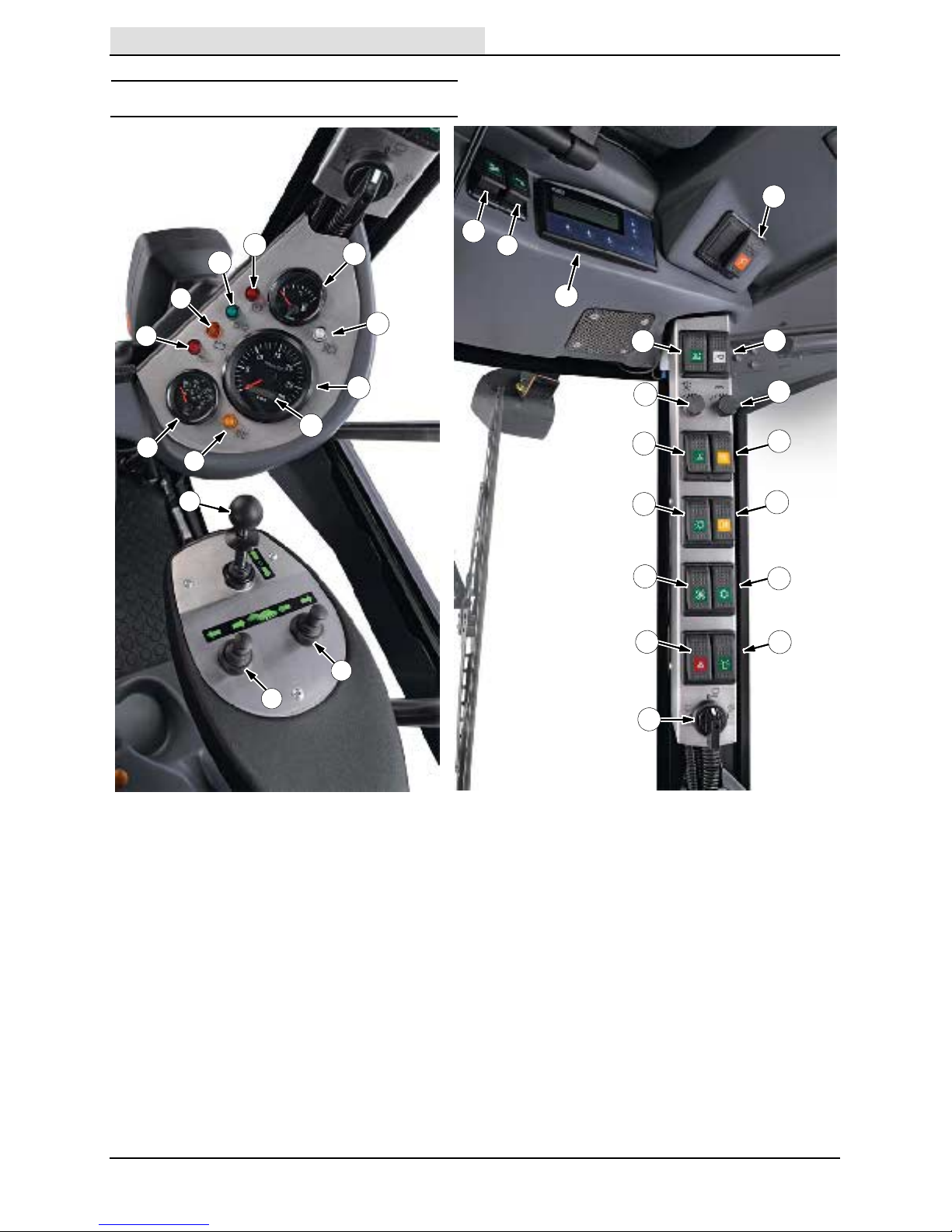
Controls And Instruments 8...............
Symbol Definitions 10.....................
Operation Of Controls 11..................
Drive Lever
(Forward / Neutral / Reverse) 11......
Brush Levers 11.......................
Fuel Gauge 11........................
Tachometer 11........................
Hour Meter 11........................
Engine Temperature Gauge 12..........
Parking Brake Indicator (Red) 12........
Turn Signal / 4--Way Warning Light
Indicator (Green) 12................
Charging System Malfunction
Indicator (Amber) 12................
Engine Oil Indicator (Red) 12...........
Headlight High Beam Indicator 12.......
Glow Plug Indicator (Amber) 13.........
Hopper Drain Switch 13................
Transit / Work Modes Switch 14.........
Brush Speed Knob 14..................
Vacuum Fan Speed Knob 15............
Vacuum Fan Speed Boost 15...........
Windshield Defroster Switch 15.........
Master Light Switch 16.................
Overhead Work Light Switch 16.........
Rear Fog Light Switch 16...............
Cab Temperature Control Knob 16.......
Heater Fan Switch 17..................
Air Conditioner (Option) 17.............
4--Way Warning Light Switch 17.........
Warning Beacon / Audible
Alarm Switch 17....................
Water Switch (Dust Suppression) 18.....
Water Flow Control Knob 18............
Brush Pressure Adjustment Knob 19.....
Parking Brake Lever 19................
Accelerator Pedal 19...................
Brake Pedal 19.......................
Steering Wheel Height
Adjustment Handle 20...............
Headlight And Multifunctional Switch 20..
Windshield Wiper / Washer Switch 20....
Horn Button 20........................
Operator Seat 21......................
Seat Belts 21.........................
Door Locks 21........................
Brush Information 22.....................
How The Machine Works 22...............
Pre--operation Checklist 23................
Post Operation Cleaning 23................
Page
Starting The Machine 24..................
Turning Off The Machine 25...............
While Operating The Machine 25...........
Sweeping 26............................
Driving Over Curbs 27....................
Raising / Lowering The Hopper 28..........
Engaging The Hopper Safety Arm 29.......
Disengaging The Hopper Safety Arm 30.....
Using The Wander Hose 30...............
Emptying The Hopper 32..................
Cleaning The Machine 33.................
Cleaning The Vacuum Fan Assembly 37....
Checking / Filling The Water Tank 37.......
Using The Machine Display
Module (MDM) System 38..............
Adjusting The Engine Speed 38............
Using The Engine Speed Boost 39.........
Machine Display Module (MDM)
Fault Screens 40......................
Options 42..............................
Pressure Washer (Option) 42...........
Rear View Camera (Option) 43..........
Radio And Compact Disk
Player (Option) 43..................
Automatic Greasing (Option) 43.........
Filling The Automatic Greasing
System Reservoir 43.............
Winter Equipment (Option) 44...........
Snow Brush (Option) 44.............
Snow Plows (Option) 45.............
Grit (Sand / Road Salt)
Dispenser (Option) 46............
Machine Troubleshooting 47...............
Conditions Table 49.......................
Maintenance 50.............................
Maintenance Chart 50....................
Lubrication 55...........................
Lubrication Points 55...................
Hydraulics 56............................
Hydraulic Hoses 57....................
Hydraulic Fluid 57.....................
Engine 58...............................
Engine Oil 58.........................
Cooling System 58....................
Engine Belt 58........................
Air Filter 59..........................
Fuel Filters 60........................
Fuel Lines 60.........................
Priming The Fuel System 60............
Valve Clearances 60...................
Battery 61
...............................
Fuses 62................................
Replacing The Fuses 62................

CONTENTS
636 9006280 (10--11)
2
Page
Brushes 63..............................
Replacing The Brushes 63..............
Adjusting The Brush Angle 63...........
Brush Linkage 64......................
Dust Suppression / Vacuum 65.............
Adjusting / Replacing The Nozzle Flap 65.
Vacuum Nozzle Skid 66................
Cast Iron Skid 66......................
Spray Jets 66.........................
CloudMaker 67........................
Water Tank 67..........................
Drain Cap Filter 67....................
Water Tank Door Retainer Chain 67......
Water Level Sensor 67.................
Hopper 68...............................
Hopper Door, Hopper Inlet, And
Vacuum Fan Access Door Seals 68...
Hopper Drain Seal 68..................
Hopper Cyclones Screens 68...........
Hopper Drain Screen 68................
Hopper External Drain Tube 69..........
Hopper Door Screen 69................
Hopper Raised Safety Switch 69........
Vacuum Fan Door Safety Switch 69......
Vacuum Fan Access Door 69...........
Cab 70..................................
Windshield Wiper Blades 70............
Rear View Camera (Option) 70..........
Windshield Washer Fluid 70...............
Steering And Suspension 71...............
Brakes And Tires 72......................
Service Brakes 72.....................
Parking Brakes 72.....................
Tires 72..............................
Wheel Torque 72......................
Wander Hose 73.........................
Pressure Washer (Option) 73..............
Tilting / Lowering The Cab 74..............
Tilting The Cab 74.....................
Lowering The Cab 74..................
Tilting / Lowering The Hopper Manually 75...
Tilting The Hopper Manually 75..........
Lowering The Hopper Manually 76.......
Towing / Transporting The Machine 77......
Towing The Machine 77................
Transporting The Machine 77...........
Machine Jacking 79......................
Storage And Freeze Protection 80..........
Storing The Machine 80................
Freeze Protection 80...................
Specifications 81............................
General Machine Dimensions/Capacities 81.
General Machine Performance 81..........
Hydraulic System 82......................
Steering 82..............................
Power Type 82...........................
Tires 82.................................
Machine Dimensions 83...................

SAFETY PRECAUTIONS
3
636 9006280 (10--11)
SAFETY PRECAUTIONS
The following precautions are used throughout
this manual as indicated in their description:
WARNING: To warn of hazards or
unsafe practices that could result in
severe personal injury or death.
CAUTION: To warn of unsafe practices
that could result in minor or moderate
personal injury.
FOR SAFETY: To identify actions that must be
followed for safe operation of equipment.
The machine is suited to sweep disposable
debris. Do not use the machine other than
described in this Operator Manual.
The following information signals potentially
dangerous conditions to the operator or
equipment:
WARNING: Moving belt and fan. Keep
away.
WARNING: Machine emits toxic gases.
Serious injury or death can result.
Provide adequate ventilation.
WARNING: Raised hopper may fall.
Engage hopper support arm.
WARNING: Lift arm pinch point. Stay
clear of hopper lift arms.
WARNING: Flammable materials can
cause explosion or fire. Do not use
flammable materials in tank. Only use
water.
WARNING: Do not spray people or
animals. Severe personal injury can
result. Wear eye protection. Hold
sprayer with two hands.
FOR SAFETY:
1. Do not operate machine:
-- Unless trained and authorized.
-- Unless operator manual is read and
understood.
-- Unless mentally and physically
capable of following machine
instructions.
-- If it is not in proper operating
condition.
-- In flammable or explosive areas.
2. Before starting machine:
-- Check for fuel, oil, and liquid leaks.
-- Keep sparks and open flame away
from refueling area.
-- Make sure all safety devices are in
place and operate properly.
-- Check brakes and steering for proper
operation.
-- Adjust seat and fasten seat belt.
3. When starting machine:
-- Keep foot on brake and place
directional lever in neutral.
4. When using machine:
-- Do not pick up burning or smoking
debris, such as cigarettes, matches or
hot ashes
-- Use brakes to stop machine.
-- Go slow on inclines and slippery
surfaces.
-- Use care when reversing machine.
-- Move machine with care when hopper
is raised.
-- Make sure adequate clearance is
available before raising hopper.
-- Do not make adjustments on Machine
Display Module (MDM) System while
the machine is moving. Always stop
machine before making adjustments.
-- Do not carry passengers on machine.
-- Always follow safety and traffic rules.
-- Report machine damage or faulty
operation immediately.
5. Before leaving or servicing machine:
-- Stop on level surface.
-- Place the drive lever in neutral.
-- Set parking brake.
-- Turn off machine.
-- Remove key from ignition.

SAFETY PRECAUTIONS
636 9006280 (2--08)
4
6. When servicing machine:
-- Avoid moving parts. Do not wear loose
clothing or jewelry.
-- Block machine tires before jacking
machine up.
-- Jack machine up at designated
locations only. Support machine with
jack stands.
-- Use hoist or jack that will support the
weight of the machine.
-- Wear eye and ear protection when
using pressurized air or water.
-- Disconnect battery connections before
working on machine.
-- Avoid contact with battery acid.
-- Avoid contact with hot engine coolant.
-- Do not remove cap from radiator when
engine is hot.
-- Allow engine to cool.
-- Keep flames and sparks away from
fuel system service area. Keep area
well ventilated.
-- Use cardboard to locate leaking
hydraulic fluid under pressure.
-- Use Tennant supplied or approved
replacement parts.
7. When loading/unloading machine
onto/off truck or trailer:
-- Turn off machine.
-- Use truck or trailer that will support
the weight of the machine.
-- Use winch. Do not drive the machine
onto/off the truck or trailer unless the
load height is 380 mm (15 in) or less
from the ground.
-- Set parking brake after machine is
loaded.
-- Block machine tires.
-- Tie machine down to truck or trailer.

SAFETY PRECAUTIONS
5
636 9006280 (2--08)
The following safety labels are mounted on the
machine in the locations indicated. If any label
becomes damaged or illegible, install a new label
in its place.

SAFETY PRECAUTIONS
636 9006280 (2--08)
6

OPERATION
7
636 9006280 (2--09)
OPERATION
MACHINE COMPONENTS
23
4
5
1
11
14
13
15
16
17
6
7
10
20
9
18
12
19
21
8
1. Wander hose
2. Hopper
3. Warning beacon
4. Overhead work lights
5. Headlights / Turn signals
6. Right access door
7. Vacuum fan access door
8. Right brush
9. CloudMaker (dust suppression)
10. Spray jets (dust suppression)
11. Rear view camera (Optional)
12. Rear fog light
13. Water tank
14. Taillights / Turn signals
15. Water tank level tube
16. Water tank door
17. Left access door
18. Wander hose access door
19. Hydraulic fluid level indicator
20. Engine compartment
21. Left brush

OPERATION
8636 9006280 (2--09)
CONTROLS AND INSTRUMENTS
1
2
4
5
6
7
8
9
11
12
10
16
18
17
19
20
21
22
23
24
25
26
27
28
3
14 15
29
30
13
1. Left Brush Lever
2. Right Brush Lever
3. Drive Lever
(Forward / Neutral / Reverse)
4. Glow Plug Indicator (Amber)
5. Engine Temperature Gauge
6. Engine Oil Indicator (Red)
7. Charging System Malfunction
Indicator (Amber)
8. Turn Signal / 4--Way Warning Light
Indicator (Green)
9. Parking Brake Indicator (Red)
10. Fuel Gauge
11. Headlight High Beam Indicator
12. Tachometer
13. Hour Meter
14. Wander Hose Switch
15. Pressure Washer Switch (Optional)
16. Machine Display Module (MDM)
17. Hopper Drain Switch
18. Hopper Raise / Lower Switch
19. Transit / Work Modes Switch
20. Brush Speed Knob
21. Vacuum Fan Speed Knob
22. Windshield Defroster Switch
23. Overhead Work Light Switch
24. Rear Fog Light Switch
25. Master Light Switch
26. Air Conditioner Switch (Optional)
27. Heater Fan Switch
28. Warning Beacon / Audible Alarm Switch
29. 4--Way Warning Light Switch
30. Water Control Knob (Dust Suppression)

OPERATION
9
636 9006280 (2--09)
2
4
13
5
8
6
7
9
10
11
1. Parking Brake Lever
2. Cab Temperature Control Knob
3. Brush Pressure Adjustment Knob
4. Water Flow Control Knob
5. Accelerator Pedal
6. Brake Pedal
7. Steering Wheel
8. Steering Wheel Height Adjustment
Handle
9. Headlight and Multifunctional Switch
10. Windshield Wiper / Washer Switch
11. Horn Button

OPERATION
10 636 9006280 (2--09)
SYMBOL DEFINITIONS
These symbols are used on the machine to
identify controls, displays, and features.
Transit / Work Mode Hazard Lights
Brush Speed Signal Light / 4--Way Hazard Light
Brush Pressure Glow Plug (Preheat)
Vacuum Fan Speed Voltmeter
Horn Air Conditioner (Option)
Warning Beacon Parking Brake
Operating Lights Bright Headlights
Windshield Defroster Overhead Lights
Oil Pressure Dust Suppression 0
Master Lights Dust Suppression 1
Heater Fan Dust Suppression 2
Rear Fog Lights Water Flow Control
Raise / Lower Hopper Wander Hose (Option)
Hopper Drain Pressure Washer (Option)

OPERATION
11
636 9006280 (2--09)
OPERATION OF CONTROLS
DRIVE LEVER
(FORWARD / NEUTRAL / REVERSE)
NOTE:Lift the lock toward the ball handle before
moving the drive lever to the desired position.
Forward: Place the Drive lever into the forward
position and press the accelerator pedal.
Neutral: Place the Drive lever into the middle
position.
Reverse: Place the Drive lever into the reverse
position and press the accelerator pedal.
BRUSH LEVERS
Use the Brush levers to adjust the brush path
width and edge sweep.
FUEL GAUGE
The Fuel gauge displays the amount of fuel in the
tank. Use diesel fuel only.
TACHOMETER
The Tachometer displays the engine speed in
rotations per minute (rpm).
HOUR METER
The Hour meter displays the number of hours the
machine was operated. Use this information to
determine machine service intervals.

OPERATION
12 636 9006280 (2--09)
ENGINE TEMPERATURE GAUGE
The Engine temperature gauge indicates the
engine temperature.
PARKING BRAKE INDICATOR (RED)
The Parking brake indicator illuminates when the
parking brake is engaged.
TURN SIGNAL / 4--WAY WARNING LIGHT
INDICATOR (GREEN)
The Turn signal /4--way warning light indicator
illuminates when the turn signals or 4--way
warning lights are activated.
CHARGING SYSTEM MALFUNCTION
INDICATOR (AMBER)
The Charging system malfunction indicator
illuminates when the alternator is not charging the
battery.
ENGINE OIL INDICATOR (RED)
The Engine oil indicator illuminates when the oil
pressure is low.
HEADLIGHT HIGH BEAM INDICATOR
The Headlight high beam indicator illuminates
when the headlight high beams are on.

OPERATION
13
636 9006280 (2--09)
GLOW PLUG INDICATOR (AMBER)
The Glow plug indicator illuminates when the
ignition switch is turned clockwise far enough to
activate light, but not far enough to start the
engine.
HOPPER DRAIN SWITCH
Use the Hopper drain switch to drain excess
water from the hopper.

OPERATION
14 636 9006280 (2--09)
TRANSIT / WORK MODES SWITCH
Transit Mode (top position) is for moving between
job sites. The machine can reach speeds up to 40
km/h (25 mph) when in this mode. The front
wheels automatically track out to provide more
stability when the machine exceeds 5 km/h
(approximately 3 mph). The brushes raise and
stop rotating, the vacuum head raises, and the
vacuum fan stops operating.
Work Mode 1 (middle position) is for sweeping.
The machine can reach speeds up to 12 km/h
(8 mph) when in this mode. If the front wheels are
in the out position, they will automatically track in
when the machine exceeds 5 km/h (approximately
3 mph). The brushes lower and begin rotating, the
vacuum head lowers, and the vacuum fan begins
operating.
Work Mode 2 (bottom position) is for moving short
distances between work areas and driving over
curbs or speed bumps. The machine can reach
speeds up to16 km/h (9 mph) when in this mode.
The brushes raise and stop rotating, the vacuum
head raises, and the vacuum fan stops operating.
The machine automatically provides increased
traction.
BRUSH SPEED KNOB
Turn the Brush speed knob clockwise to increase
the speed of both brushes and counterclockwise
to decrease the speed of both brushes.

OPERATION
15
636 9006280 (9--09)
VACUUM FAN SPEED KNOB
Turn the Vacuum fan speed knob clockwise to
increase the vacuum and counterclockwise to
decrease the vacuum.
NOTE: For normal operating conditions the
vacuum fan speed should be set to below 2400
rpm.
VACUUM FAN SPEED BOOST
The vacuum fan speed can be set to above 2400
rpm (boost) for a short time (5 minutes). A
countdown bar appears on the MDM display.
Reduce the vacuum fan speed to less than 2400
rpm before the countdown bar expires. It must be
reduced for at least 30 seconds or the machine
must be stopped and the drive lever placed in
neutral for five seconds before returning to
vacuum fan speed boost. If not, an audible alarm
will sound at the end of the five minutes, the fan
will shut off, and a warning message will appear
on the MDM display.
To reset the vacuum fan speed boost limiting
system, stop the machine and place the drive
lever in neutral. Restart the machine and turn the
vacuum speed to below 2400 rpm.
This vacuum fan speed boost is available for only
five 5--minute intervals per hour. After five boost
periods, the vacuum fan speed will be limited to
2300 rpm for the rest of the hour
WINDSHIELD DEFROSTER SWITCH
Use the Windshield defroster switch to defrost the
windshield.

OPERATION
16 636 9006280 (2--09)
MASTER LIGHT SWITCH
Use the 3--position Master light switch to control
the headlights, overhead work lights, and rear fog
lights. Push the switch to the second position to
operate only the headlights. Push the switch back
to the first position to turn off all lights.
Push the switch to the third position to operate the
headlights and allow use of the overhead work
lights and rear fog lights.
NOTE: The rear fog light and overhead work light
switches must be in the on position for the lights
to function.
OVERHEAD WORK LIGHT SWITCH
Use the Overhead work light switch to operate the
overhead work lights. The Master light switch
must be in the third position to operate the
overhead work lights.
REAR FOG LIGHT SWITCH
Use the Rear fog light switch to operate the rear
fog lights. The Master light switch must be in the
third position to operate the rear fog lights.
CAB TEMPERATURE CONTROL KNOB
Turn the Cab temperature control knob clockwise
to increase the temperature and counterclockwise
to decrease the temperature inside the cab when
the heater is on.

OPERATION
17
636 9006280 (2--09)
HEATER FAN SWITCH
Use the 2--speed Heater fan speed switch to
operate / adjust the heater fan.
AIR CONDITIONER (OPTION)
Use the 2--speed Air conditioner fan speed switch
to operate / adjust the air conditioner fan.
4--WAY WARNING LIGHT SWITCH
Use the 4--way warning light switch to operate the
4--way warning lights.
WARNING BEACON / AUDIBLE ALARM
SWITCH
Use the 3--position Warning beacon / audible
alarm switch to activate the warning beacon and
audible alarm. Push the switch to the second
(middle) position to operate only the warning
beacon.
Push the switch to the third (lower) position to
operate both the warning beacon and audible
alarm. Push the switch back to the first position to
turn off the warning beacon and audible alarm.
The warning beacon can be swung back behind
the cab to allow for lower clearances.

OPERATION
18 636 9006280 (2--09)
WATER SWITCH (DUST SUPPRESSION)
Turn the water switch to position 0 in areas where
dust suppression is not necessary. Neither the
brush head spray jets nor the vacuum tube spray
jets operate in this mode. The CloudMaker nozzle
continues to rotate to keep the spray head clean,
but does not use water.
Turn the water switch to position 1 for dry areas
where full dust suppression is necessary. The
CloudMaker nozzle, brush head spray jets, and
vacuum tube spray jet operate in this mode.
Turn the water switch to position 2 in areas where
some dust suppression (wet sweeping) is
necessary. Only the brush head spray jets and
vacuum tube spray jets operate in this mode. The
CloudMaker nozzle continues to rotate to keep
the spray head clean, but does not use water.
WATER FLOW CONTROL KNOB
Turn the Water flow control knob clockwise to
decrease the amount of water supplied to the
brush jets and counterclockwise to increase the
amount of water to the brush jets.
NOTE: To operate only the CloudMaker and
conserve water, turn the water switch to position 1
and the water flow control knob to the minimum
flow setting to turn off the water to the brush
spray jets.
Table of contents
Other Green Machines Blower manuals
Popular Blower manuals by other brands

Canarm
Canarm 400 Series Operation instructions and parts manual

matev
matev SWE-45 operating manual

Weed Eater
Weed Eater 545146904 instruction manual

Greencut
Greencut EB260X instruction manual

Solo
Solo Master 466 Evolution Original instructions

Spear & Jackson
Spear & Jackson SCBV36 Original instruction manual