Greenfield GFT9404 User manual

GFT9404
EIGHTCHANNELDIGITALDELAYGENERATOR
USERMANUAL
Four high resolution delay channels
o1 ps delay resolution
o< 50 ps rms jitter + delay x10-7
o> 20 second delay range
Four auxiliary delay channels
o5 ns delay resolution
o< 100 ps rms jitter + delay x10-7
o> 20 second delay range
oAvailable on front panel and PXI TRIG
Four sources of trigger: external, internal, PXI STAR
and software trigger
Two trigger modes: single shot or repetitive
One Slot 3U PXI, hybrid compatible
Totalsheets:21
GREENFIELD TECHNOLOGY
NUT018.Ed.3.1
06/2010
USERMANUAL

NUT 018 Ed. 3.1 février 16
©GREENFIELDTECHNOLOGY 2GFT9404UserManual
CONTENT
1.GENERAL INFORMATION ....................................................................................................... 4
What do you need to get started.......................................................................................................................... 5
Unpacking........................................................................................................................................................... 5
2.INSTALLING AND CONFIGURING......................................................................................... 6
Installing the Software ........................................................................................................................................ 6
Installing the Hardware....................................................................................................................................... 6
3.OPERATING INFORMATION................................................................................................... 7
Functional Overview........................................................................................................................................... 7
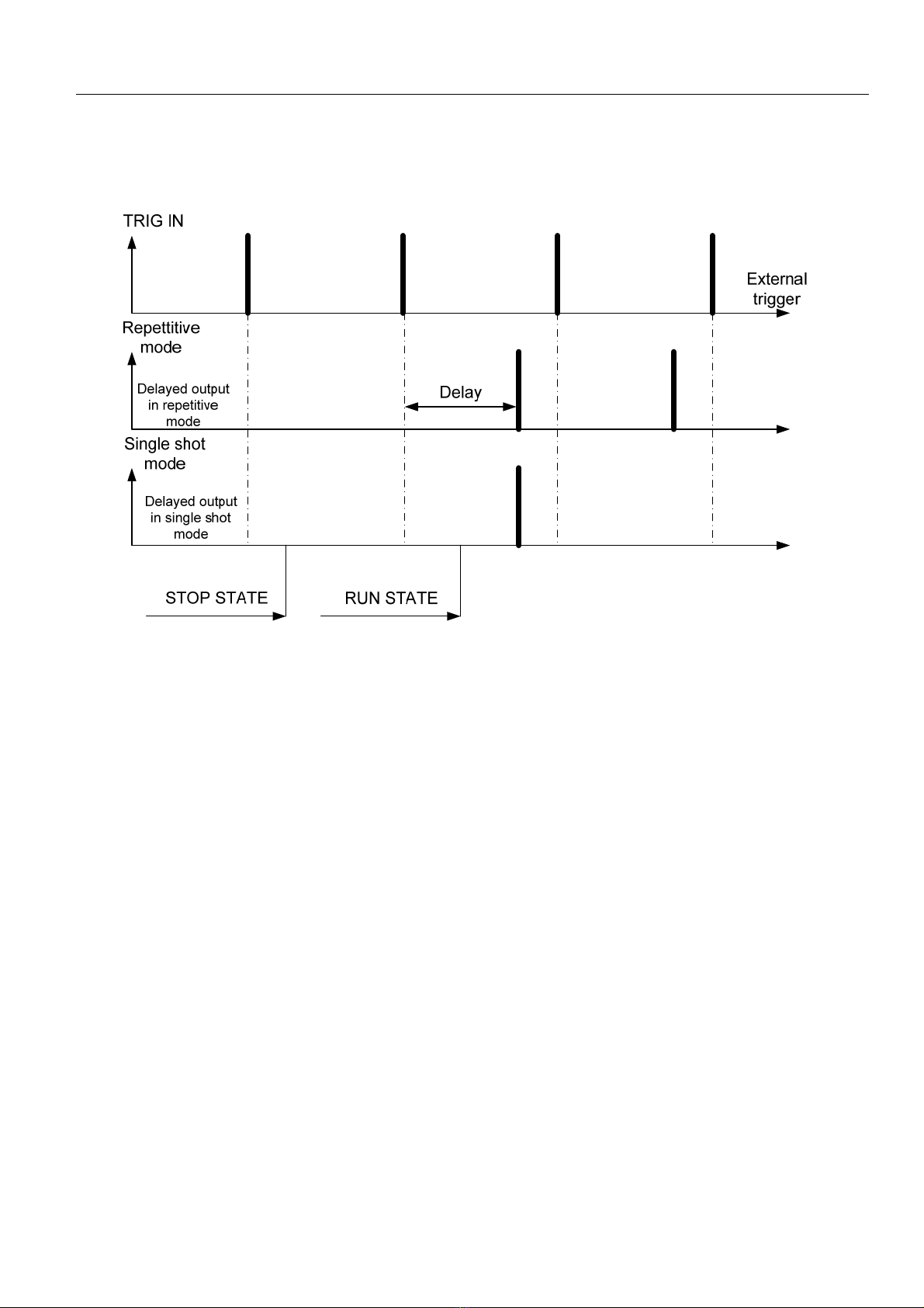
Timing Principle Using External Triggering....................................................................................................... 8
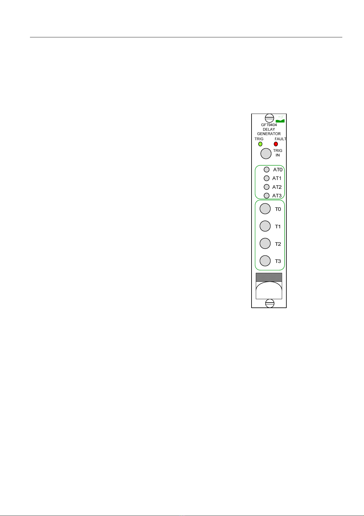
Front Panel.......................................................................................................................................................... 9
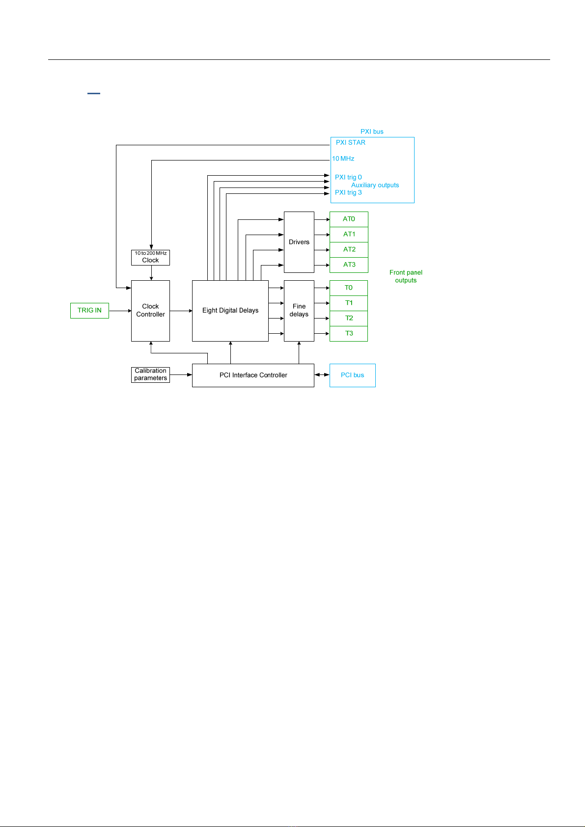
Trigger Routing Architecture............................................................................................................................ 10
Self-Test............................................................................................................................................................ 10
Status................................................................................................................................................................. 11
Multiple Board Synchronization....................................................................................................................... 11
4.APPLICATION SOFTWARE.................................................................................................... 13
Connecting a Board........................................................................................................................................... 13
Board Setup....................................................................................................................................................... 14
Delay Reference................................................................................................................................................ 15
Channel Setup................................................................................................................................................... 15
Trigger Setup .................................................................................................................................................... 16
RUN and STOP Delay Sequence...................................................................................................................... 16
Checking Board Status...................................................................................................................................... 17
Saving and Loading Configuration Files .......................................................................................................... 18
APPENDIX A: SPECIFICATIONS.................................................................................................. 19
APPENDIX B: TECHNICAL SUPPORT AND PROFESSIONAL SERVICES.......................... 21

NUT 018 Ed. 3.1 février 16
©GREENFIELDTECHNOLOGY 3GFT9404UserManual
EDITION
Ed.DateDescription
115/05/2009Creation
230/09/2009Updatethespecification
327/07/2010Updatethespecification
3.126/02/2016MinorcorrectionBoardsetupsection.

NUT 018 Ed. 3.1 février 16
©GREENFIELDTECHNOLOGY 4GFT9404UserManual
1. GENERALINFORMATION
TheGFT9404moduleprovidesfourindependentdelaychannels(T0toT3).Thedelayresolutionis
1ps,andtrigger‐to‐channeljitterislessthan50ps.SMBoutputsdeliver5V,2nsrisetime,under
50Ω.Amplitudeandwidthareadjustableoneachoutputchannel.
TheGFT9404alsoprovidesfourauxiliarydelaychannelsavailableonthefrontpanel(AT0toAT3)
and/oronPXItriggerlines(PXITRIG0toPXITRIG3).Thedelayresolutionis5ns(onetimebase
clock),andtrigger‐to‐channeljitteris100ps.
Oneinputtrigger(TRIGIN),PXISTAR,internalfrequency,orsoftwaretriggerisusedtotriggeroff
alloutputchannels.
Themoduleofferstwooperatingtriggermodes,repetitiveorsingleshot.
ThecontrolpanelsoftwareforWindowsprovidesasimplemethodtoconfiguresettingsforeach
channel,suchasamplitude,width,triggersource,andtriggermode,andtocontroloperation.You
cansaveandrecallsettings.ThesoftwareallowsyoutoinstallandoperatemultipleGFT9404
boardsinthesamePXIchassis.Themoduleserialnumberspecifiesthemoduleaddress.
TheGFT9404istheidealinstrumenttoprovidepreciselytimedpulses,asencounteredin
picosecondlasersystemandotheracceleratorapplications.
PackageContents
Theboxyoureceivedshouldcontainthefollowing:
GFT9404 module,
CD containing the PDF user manual, LabVIEW driver, and GFT9404 application
software,
Certificate of calibration.

NUT 018 Ed. 3.1 février 16
©GREENFIELDTECHNOLOGY 5GFT9404UserManual
Whatdoyouneedtogetstarted
To set up and use the GFT9404, you need the following items:
GFT9404 delay generator,
GFT9404 user manual,
GFT9404 CD driver,
NI-VISA,
PXI chassis, or PXI Express chassis with hybrid slots,
PXI embedded controller or a computer connected to the PXI chassis using MXI.
Unpacking
The GFT9404 is shipped in an antistatic package to prevent electrostatic damage to the
module. Electrostatic discharge (ESD) can damage several components on the module.
Caution: Never touch the exposed pins of connectors.
To avoid such damage when handling the module, take the following precautions:
Ground yourself using a grounding strap or by touching a grounded object.
Touch the antistatic package to a metal part of the computer chassis before removing
the module from the package.
Remove the module from the package and inspect the module for loose components or any
sign of damage. Notify Greenfield Technology if the module appears damaged in any way. Do
not install a damaged module into the computer.
Store the GFT9404 in the antistatic package when not in use.

NUT 018 Ed. 3.1 février 16
©GREENFIELDTECHNOLOGY 6GFT9404UserManual
2. INSTALLINGANDCONFIGURING
This chapter describes how to install the GFT9404 hardware and software and how to
configure the device.
InstallingtheSoftware
Refer to the readme.htm file on the GFT9404 CD for software installation directions.
Note : be sure to install the driver software before installing the GFT9404 hardware.
The software includes a control application for using the board directly, as well as a library for
designing C/C++ applications and LabVIEW VIs.
This release of the GFT9404 control application supports Microsoft Windows XP SP2, Vista,
and Windows 7.
For application development, you need either a C/C++ compiler and an IDE such as Visual
Studio, or LabVIEW.
InstallingtheHardware
The following information provides general installation instructions. Consult the chassis user
manual or technical reference manual for specific instructions and warnings about installing
new modules.
1. Power off and unplug the chassis.
2. Choose an available PXI or PXI hybrid slot in the chassis.
3. Remove the filler panel for the PXI slot you chose in step 2.
4. Ground yourself using a grounding strap or by touching a grounded object. Follow the ESD
protection precautions described in the Unpacking section of Chapter 1, General information.
5. Insert the GFT9404 into the PXI slot. Use the ejector handle to fully insert the module into
the chassis.
6. Screw the front panel of the device to the front panel mounting rail of the chassis.
7. Visually verify the installation. Make sure the module is not touching other modules or
components and is fully inserted into the slot.
8. Plug in and power on the chassis.

NUT 018 Ed. 3.1 février 16
©GREENFIELDTECHNOLOGY 7GFT9404UserManual
3. OPERATINGINFORMATION
FunctionalOverview
Figure3‐1FunctionalOverview
When the module is in the RUN state, a rising edge on a trigger starts a delay sequence. The
internal trigger comes from TRIG IN, PXI STAR, or software trigger.
The sequence includes two external trigger phases:
After an insertion delay, a pulse appears on each channel after a specified delay
At the end of sequence, after the last delayed pulse, the delay generator is ready for
repetitive trigger mode.
When a sequence is in progress, the instrument does not respond to any trigger event.
The GFT9404 must be configured (trigger, delay, etc.) in the STOP state before starting any
sequence. In the STOP state, outputs are automatically disabled.
When a delay sequence starts, the green front panel LED turns on for 1 second.

NUT 018 Ed. 3.1 février 16
©GREENFIELDTECHNOLOGY 8GFT9404UserManual
TimingPrincipleUsingExternalTriggering
Figure3‐2TriggerTiming
In response to the input trigger the board can generate a single delayed output (single shot
mode) or repetitive delayed outputs (repetitive mode).
Calibration parameters are saved onboard.

NUT 018 Ed. 3.1 février 16
©GREENFIELDTECHNOLOGY 9GFT9404UserManual
FrontPanel
The GFT9404 fits into a single slot of a 3U PXI or PXI Express hybrid chassis.
The front panel has two LEDs and 9 connectors.
LEDs
TRIG(green)Lightsonwhenatriggeris
detected
FAULT(red)Lightsonifafaultisdetected
ConnectorsSMBtype
TRIGINExternaltriggerinput
T0toT3Fourhighresolutionoutputs
ConnectorsMMCXtype
AT0toAT3Fourauxiliaryoutputs
Ejectorhandle
Includesalabelwiththeserialnumber
Figure3‐3FrontPanel

NUT 018 Ed. 3.1 février 16
©GREENFIELDTECHNOLOGY 10GFT9404UserManual
TriggerRoutingArchitecture
Thetablebelowlistsavailableconnections.Ifaparticularcellisfilledin,theconnectionispossible.If
acellisempty,thisconnectionisnotpossible.
Destinations
FrontPanelBackplaneOnboard
Front
Panel
T<0..3>AT<0..3>PXI_CLK10
STAR
TRIGGER<0..12>
PXI
TRIG<0..7>Clock
TRIGINX(1)X(2) 0..3(2)
Internal
X(1)X(2)0..3(2)
Backplane
PXI_CLK10 X
STAR
TRIGGER<0..12>X(1)X(2)0..3(2)
PXI_TRIG<0..7>
Onboard
Clock
GlobalSW
TriggerX(1)X(2)0..3(2)
(1)Resolution=1ps
(2)Resolution=5ns
Triggers available on the PXI_TRIG lines are copies of the auxiliary triggers. Accordingly, to
control the delay on a PXI_TRIG line you have to set the appropriate delay for the
corresponding auxiliary trigger. The mapping is as follows: AT0 is available on PXI _TRIG0,
AT1 on PXI_TRIG1, AT2 on PXI_TRIG2, and AT3 on PXI_TRIG3. Note that, in order to avoid
accidental “double driving” of PXI_TRIG lines when using multiple boards in the same chassis,
triggers on PXI_TRIG lines are disabled by default. You will have to issue a specific software
call to enable the copy of an auxiliary trigger to the corresponding PXI_TRIG line.
Self‐Test
The red FAULT LED indicates whether the board has one of the following problems:
Loss of 10 MHz PXI backplane
PLL unlock
Oscillator unlock

NUT 018 Ed. 3.1 février 16
©GREENFIELDTECHNOLOGY 11GFT9404UserManual
Status
Foreachchannel,astatusindicatorshowsifthechannelhasgeneratedthepulses.
In single shot mode, this status indicator is erased when the RUN state is activated.
In repetitive mode, this status is erased when the STOP state is activated.
MultipleBoardSynchronization
Externaltriggercopy:
T0
TRIG
IN
T1
T2
T3
AT0
AT1
AT2
AT3
TRIG FAULT
GFT9404
DELAY
GENERATOR
T0
TRIG
IN
T1
T2
T3
AT0
AT1
AT2
AT3
TRIG FAULT
GFT9404
DELAY
GENERATOR
TRIG
IN
TRIG
IN / 2
TRIG
IN / 2
T splitter
Figure3‐4MultipleBoardSynchronization
WithaTsplitter(e.g.RadiallreferenceR114781000),youcansynchronizemultipleboards(passive
solution)asshownabove.
WithanyNIPXI‐665X,PXIe‐6672,orPXI‐6682board,multipleGFT9404boardscanbesynchronized
usingthePXISTARlines.

NUT 018 Ed. 3.1 février 16
©GREENFIELDTECHNOLOGY 12GFT9404UserManual
Fivemodulessynchronized:
Thisconfigurationprovides36synchronizeddelayedoutputsfromasingletriggersource.Theuseof
anexternaltriggersourceisshownbelow.TheGFT9404boardontheleftisusedtocontrolthe
sourceoftriggerstosynchronizethefourotherGFT9494boardsviatheAT0toAT3outputs.
T0
TRIG
IN
T1
T2
T3
AT0
AT1
AT2
AT3
TRIG FAULT
GFT9404
DELAY
GENERATOR
T0
TRIG
IN
T1
T2
T3
AT0
AT1
AT2
AT3
TRIG FAULT
GFT9404
DELAY
GENERATOR
T0
TRIG
IN
T1
T2
T3
AT0
AT1
AT2
AT3
TRIG FAULT
GFT9404
DELAY
GENERATOR
T0
TRIG
IN
T1
T2
T3
AT0
AT1
AT2
AT3
TRIG FAULT
GFT9404
DELAY
GENERATOR
T0
TRIG
IN
T1
T2
T3
AT0
AT1
AT2
AT3
TRIG FAULT
GFT9404
DELAY
GENERATOR

NUT 018 Ed. 3.1 février 16
©GREENFIELDTECHNOLOGY 13GFT9404UserManual
4. APPLICATIONSOFTWARE
ConnectingaBoard
StarttheGFT9404controlapplicationbydoubleclickingthegft9404.exefileorbyusingthemenu
command<Start>‐>Programs‐>Gft9404–PXIdelayGeneratorforVISA‐>Gf9404–PXIdelay
GeneratorforVISA.
Themainapplicationwindowisshownbelow.
Forconnectingthesoftwaretoaboard,useFile‐>OpenadeviceorusetheshortcutCtrl+O.
Thisopensawindowthatshowsalistofboardsfoundinthesystem.

NUT 018 Ed. 3.1 février 16
©GREENFIELDTECHNOLOGY 14GFT9404UserManual
SelecttheboardyouwanttoconnecttoandclicktheOKbuttonordoubleclickontheboardinthe
listtoconnecttheboardtothecontrolapplication.Thecontrolapplicationreadstheregistersofthe
boardandshowsthedelays,amplitude,widthandtriggervaluesonthepanel.
Iftheboardisinpoweronstate,thecontrolapplicationconfigurestheboardwithdefaultvalues.
BoardSetup
Thefrontpanelincludessomebuttonsandnumericdisplaystoconfigureandruntheboard.The
elementsofthepanelcanbeaccesseddirectlywiththemouseorthroughthekeyboardusingthe
TABorShiftTABkeys.Whenanelementisselected,athinredlinesurroundsit.
Whenselected,theusermaychangeabuttonstatebypressingthespacekey.
Numericelementsaremodifiedwiththearrowkeys,bymovingthemouseorbythemousewheel.
Tomodifyanumberyoucanplacethecursoronthenumber,presstheleftmousebuttonandmove
themouseupordownwhilekeepingtheleftmousebuttonpressed.Thenumberwillbe
incrementedordecrementedbyavaluedependingoftheweightofthedigitinthenumber.Tohelp
selectingtheweightoftheincrement,thedigitselectedisunderlined.
Forexample,ifthenumbercontainsthevalue1234.56andyoupressthemousebuttononthedigit
2,thenumberwillincrementordecrementbyavalueof100.
Hereisanexamplewhenpressingtheleftmousebuttononthedigit2

NUT 018 Ed. 3.1 février 16
©GREENFIELDTECHNOLOGY 15GFT9404UserManual
And,whenmovingthemouseupwhilekeepingtheleftbuttonpressed
Intheexampleabove,iftheusermovesthemouseslowlytheincrementis100.Iftheusermovesthe
mousequickly,theincrementwillbe1000.
DelayReference
Delayscanbeexpressedasabsolutedelays,wherethereferenceisthetimeoftheincomingtrigger,
orasrelativedelays,wherethereferenceisthetimeoftheincomingdelayplustheminimum
insertiondelay.Astheinsertiondelayisasmall,butnon‐zerodelay(typicallyoftheorderof50ns),
anyabsolutedelayhastobeatleastaslongastheinsertiondelay.However,whenusingrelative
delays,adelayvalueofzeroispossible.
ChannelSetup
Channelsetupisdonesimplybychoosingthedelay,amplitudeandwidthforeachchannel.
SetthechannelenablebuttontoONtoenabletriggeroutputforthatchannel.

NUT 018 Ed. 3.1 février 16
©GREENFIELDTECHNOLOGY 16GFT9404UserManual
TriggerSetup
Thetriggersignalcanhavemanysourcesandcharacteristics.
Triggersource
TriggerDescriptionLevelFrequency
Thetriggersignalcomesfromthefrontpanelconnectoror
fromthePXIbus
Thetriggersignalcomesfromtheboardinternalfrequency.
Inthiscase,thetriggermodeisrepetitive.Triggerinputand
polarityareignored.
Thetriggersignalcomesfromthefrontpanel'strigger
connector.
ThetriggersignalcomesfromthePXISTARtriggerline.
Triggermode
ModeDescriptionEXTINT
Theboardisinsingleshotmode.Enabledchannels output
onlyonepulseonthefirsttriggersignaloccurrence.
Theboardisinrepetitivemode.Enabledchannelsoutputa
pulseforeachtriggersignaloccurrence.
Triggerslope
ModeDescriptionEXTINT
Thedelaysstartonthelowtohightransitionofthetrigger
signal.
Thedelaysstartonthehightolowtransitionofthetrigger
signal.
RUNandSTOPDelaySequence
Tostartadelaysequence,clickontheRUNSTOPbutton.Whentheboardisinrunningmode,the
panelelementsaredisabled(withtheexceptionofthemanualtriggerbutton).
Whentheboardisinsingleshottriggermode,theboardstopsafterthefirsttrigger.
Whentheboardisinrepetitivemode,clickontheRUNSTOPbuttontostoptheboard.

NUT 018 Ed. 3.1 février 16
©GREENFIELDTECHNOLOGY 17GFT9404UserManual
CheckingBoardStatus
Tochecktheboardstatus,theapplicationpanelprovidesasummaryoftheerrorflagsanda
summaryofthetriggerflags.
ThefaultLEDisonifoneoftheboard'serrorflagsison.ThisLEDisonaslongasanerrorispresent.
ThetriggerLEDisonforonesecondwhentheboardisinrepetitivemodeandatleastonechannel
hastriggered.Iftheboardisinsingleshottriggermode,theLEDisonassoonasachannelhas
triggeredandremainsonuntiltheboardisstartedagain.
Thefullstatusoftheboardisavailablebyselectingthestatusmenu.
Choosingthismenuitemopensthestatuswindow.
Thiswindowshowsthethreeerrorflagsandtheeighttriggerflagsoftheboard.

NUT 018 Ed. 3.1 février 16
©GREENFIELDTECHNOLOGY 18GFT9404UserManual
SavingandLoadingConfigurationFiles
Acompleteboardconfigurationcanbesavedorloadedwiththemenuitems"Saveconfig"or"Load
config".
The"Saveconfig"menuitemsavesthecompleteboardconfigurationinanXMLfilethatcanbelater
reloadedwiththe"Loadconfig"menuitem.

NUT 018 Ed. 3.1 février 16
©GREENFIELDTECHNOLOGY 19GFT9404UserManual
AppendixA:Specifications
Dela
y
s
Channels Four inde
p
endent dela
y
out
p
uts
Ran
g
e 0 to > 20 seconds
Resolution < 10
p
s
RMS
j
itter
(
External tri
gg
er to an
y
50
p
s rms + dela
y
x 10-7
A
ccurac
y
< 250
p
s + dela
y
x 10-7
Time base 200 MHz, 25
pp
m
Time reference from PXI bus 10 MHz, 25
pp
m from PXI bus
Auxiliar
y
Dela
y
s
Channels Four inde
p
endent dela
y
out
p
uts
Ran
g
e 0 to > 20 seconds
Resolution 5 ns
RMS
j
itter
(
External tri
gg
er to an
y
100
p
s rms + dela
y
x 10-7
A
ccurac
y
1 ns + dela
y
x 10-7
Tri
gg
e
r
source
Internal
Fre
q
uenc
y
1 Hz to 10 kHz, ste
p
= 1 Hz
External
Max re
p
etition rate < 50 kHz
Tri
gg
er level, From 0.1 to 5 V
Tri
gg
er slo
p
e Positive or ne
g
ative
Minimum tri
gg
er Dela
y
< 50 ns
PXI bus tri
gg
er PXI STAR
Soft tri
gg
er
Tri
gg
er mode
Sin
g
le shot or re
p
etitive
Out
p
ut T0 to T3
A
m
p
litude 2 to 5 V
Width 200 ns to 10
µ
s
Load 50 Ω
Rise time < 2 ns
Fall time < 5 ns
Connector SMB

NUT 018 Ed. 3.1 février 16
©GREENFIELDTECHNOLOGY 20GFT9404UserManual
Out
p
ut AT0 to AT3
A
m
p
litude 5 V
Width 200 ns
Load 50 Ω
Rise time < 5 ns
Fall time < 5 ns
Additional PXI TRIG
A
m
p
litude, rise and fall time PXI standard
Width 25 ns
Connector PXI connector
General
Size PXI, 1 slot
Power 15 W
(
on + 3.3 V / + 5 V / + 12 V
)
LEDs Red : fault;
g
reen : tri
gg
er on
Environmental
A
mbient tem
p
erature ran
g
e + 10 to 40 °C
Indoor use onl
y
Free LabVIEW driver for Windows XP, Vista, and Windows 7, based on NI-VISA
Table of contents
Popular Portable Generator manuals by other brands

Champion Global Power Equipment
Champion Global Power Equipment 201242 quick start guide

iPower
iPower AP10000E quick start guide

Sportsman
Sportsman GEN9000DF instruction manual

Kohler
Kohler 14EKOZD Installation

Zipper Mowers
Zipper Mowers ZI-STE2000IV Operation manual

Lincoln Electric
Lincoln Electric NERTAJET 50 AUTO Instruction for operation and maintenance