Global S-8500 User manual

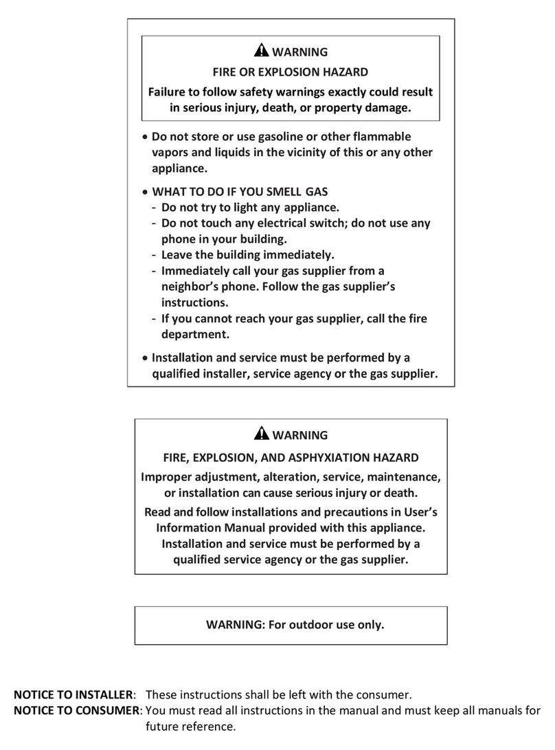
- Do not store or use gasoline or other flammable
vapors and liquids in the vicinity of this or any
other appliance.
- WHAT TO DO IF YOU SMELL GAS:
• Do not try to light any appliance.
• Do not touch any electrical switch; do not use
any phone in your building.
• Immediately call your gas supplier from a
neighbour’s phone. Follow the gas supplier’s
instructions.
• If you cannot reach your gas supplier, call the
fire department.
WARNING: If the information in this manual
is not followed exactly, a fire or explosion
may result causing property damage, personal
injury or loss of life.
WARNING: Improper installation,
adjustment, alteration, service or
maintenance can cause injury
or property damage. Read the
installation, operating and maintenance
instructions thoroughly before installing
or servicing this equipment.
WARNING: For Outdoor Use Only

- Ne pas entreposer ou utiliser de l’essence,
d’autres liquides ou vapeurs inflammables à
proximité de cet appareil ou d’aucun autre
appareil.
- QUE FAIRE SI VOUS SENTEZ LE GAZ:
• N’allumez aucun appareil
• Ne touchez aucun commutateur électrique;
n’utilisez pas le téléphone de votre bâtiment
• Appelez immédiatement votre fournisseur de
gaz d’un téléphone dans un bâtiment voisin, si
possible. Suivez les instructions du fournisseur
de gaz.
• Si vous ne pouvez pas atteindre votre
fournisseur de gaz, appelez le service
d’incendie.
AVERTISSEMENT: L’installation
inexacte, l’ajustement, le changement,
le service ou l’entretien peuvent cau-
ser des dommages ou des dégâts
matériaux. Lisez les instructions d’ins-
tallation, d’opération et d’entretien
complètement avant d’installer ou
entretenir cet équipement.
AVERTISSEMENT: Pour l’usage extérieur seulement
AVERTISSEMENT: si l’information de ce
manuel n’est pas suivie exactement, un incen-
die ou une explosion peut résulter entraînant
des dégâts matériaux, des blessures ou la
perte de vie.

S-8500
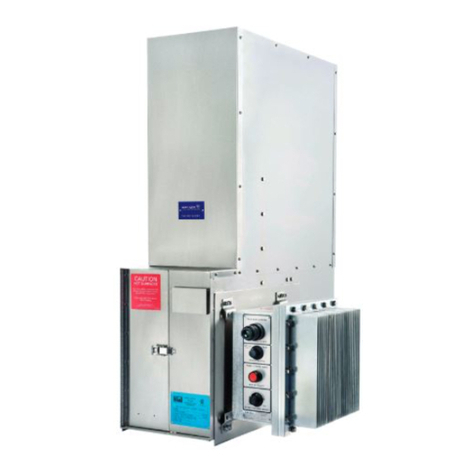
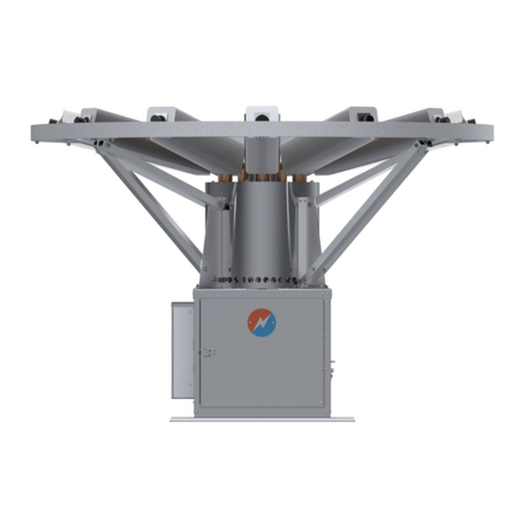
THERMOELECTRIC GENERATOR
Operating Manual
#16, 7875 - 57th Street SE
Calgary, Alberta Canada T2C 5K7
Main: +1 403 236 5556
Fax: +1 403 236 5575
www.globalte.com
64131 Rev 2
CSA T.I.L R-10 Thermoelectric Generators


TABLE OF CONTENTS
1 WARNINGS & CAUTIONS .................................................1
1.1 WARNINGS & CAUTIONS ..............................................1
1.2 GENERAL INFORMATION ..............................................2
2 ABOUT THIS MANUAL. . . . . . . . . . . . . . . . . . . . . . . . . . . . . . . . . . . . . . . . . . . . . . . . . . . .3
2.1 SITE PREPARATION...................................................3
2.2 UNPACKING..........................................................3
2.3 ASSEMBLY ...........................................................4
2.4 CONNECTING THE FUEL SUPPLY.......................................5
2.5 FUEL CONSIDERATION................................................5
2.6 CONNECTING CUSTOMER LOAD .......................................6
3 INSTALLATION ..........................................................7
3.1 BEFORE STARTING ...................................................7
3.2 TEG START-UP .......................................................7
3.3 POWER OUTPUT EVALUATION .........................................9
3.4 LEAVING THE SITE...................................................10
3.5 SHUT-DOWN ........................................................11
4 OPERATION............................................................12
4.1 UNDERSTANDING THE DATA..........................................12
4.2 POWER UNIT POWER CURVE .........................................13
4.3 TARGET SET-UP POWER CALCULATION................................15
4.4 CUSTOMER POWER OUTPUT .........................................16
5 PERFORMANCE ........................................................17
5.1 FUEL SYSTEM.......................................................17
5.2 BURNER MAINTENANCE .............................................18
5.3 SI SYSTEM MAINTENANCE ...........................................19
5.4 COOLING SYSTEM...................................................21
6 TROUBLESHOOTING....................................................23
APPENDIX ................................................................25
APPENDIX A: TERMS & DEFINITIONS ......................................25
APPENDIX B: TECHNICAL SPECIFICATIONS ................................26
APPENDIX C: UNPACKING & INSTALLATION CLARIFICATIONS ..................30
APPENDIX D: ELECTRICAL SCHEMATICS & CONNECTIONS ....................31
APPENDIX E: SERVICE & INSTALLATION TOOLS ............................33
APPENDIX F: PARTS LIST .................................................34
APPENDIX G: SPARK IGNITION SYSTEM ....................................42
APPENDIX H: HIGH POWER LIMITER ELECTRONICS ..........................43
APPENDIX I: OPTIONS....................................................47
APPENDIX J: BATTERY CHARGING OPERATION ..............................61
APPENDIX K: TEG PERFORMANCE LOG ....................................67


Global Power Technologies 1
S-8500
1 ABOUT THIS MANUAL
1.1 WARNINGS & CAUTIONS
WARNINGS
Throughout this manual paragraphs preceded by the text WARNING, it is
imperative that the advice in these paragraphs be adhered to, as failure
to do so may result in personal injury or death and possible damage to
the equipment.
CAUTIONS
Throughout this manual paragraphs preceded by the text CAUTION, it is imperative
that the advice in these paragraphs be adhered to, as failure to do so may result in
damage to the equipment.
WARNING: The installation must conform with local codes or, in the absence of local
codes, with the CSA-B149.1, Natural Gas and Propane Installation Code
and CSA-B149.2, Propane Storage and Handling Code.
WARNING: The Thermoelectric Generator, when installed, must be electrically
grounded in accordance with local codes or, in the absence of local
codes, with the Canadian Electrical Code, CSA C22.1.
CAUTION: The Thermoelectric Generator and its individual shut-off valve must be
disconnected from the gas supply piping system during any pressure
testing of that system at test pressures in excess of 3.5 kPa (1/2 psi).
The Thermoelectric Generator must be isolated from the gas supply pip-
ing system by closing its individual manual shut-off valve during any
pressure testing of the gas supply piping system at test pressures equal
to or less than 3.5 kPa (1/2 psi).
WARNING: Keep the Thermoelectric Generator area clear and free from combustible
materials, gasoline and other flammable vapors and liquids. Maintain
minimum clearances specified in this manual.
WARNING: The Thermoelectric Generator consists of sub-systems that combust
gaseous fuel and others that consume excess power through resistors,
all of which can pose high surface temperature hazards. Operators and
service personnel should avoid indicated areas of the generator to avoid
burns or clothing ignition when in operation or cooling down.
WARNING: Any guard or other protective device removed for servicing the
Thermoelectric Generator must be replaced prior to operating the appli-
ance.
WARNING: Installation and repair should be performed by a qualified service per-
son. The Thermoelectric Generator should be inspected before use and
at least annually by a qualified service person. More frequent cleaning
may be required as necessary. It is imperative that control compartment,
burners and circulating air passageways of the appliance be kept clean.

Global Power Technologies 2
S-8500
1.2 GENERAL INFORMATION
This manual provides instructions for the installation, operation, performance, basic
maintenance and troubleshooting of the model S-8500 Thermoelectric Generator (TEG),
a device that produces electrical power through the direct conversion of heat energy to
electrical energy.
Appendices provide reference details for the Technical Specifications, Wiring diagrams and
electrical schematics, Parts lists and Options.
WARNINGS and CAUTIONS are important to understanding any limitations of the device
placed on its installation and operation in a safe manner as is intended by the design.
The model S-8500 TEG has been independently tested by Intertek and certified to CSA
T.I.L.-R10 Thermoelectric Generators and is authorised to carry the ETL mark.
WARNING Do not use this Thermoelectric Generator if any part has been under
water. Immediately call a qualified service technician to inspect the appli-
ance and to replace any part of the control system and any gas control
which has been under water.
WARNING: The Thermoelectric Generator must be mechanically installed according
to the instructions contained within this manual. The Generator has a
mass of 273KG (603 lbs), a high center of gravity, and a low tipping angle
of 11 degrees from vertical. The Generator must be securely bolted to a
mounting pad or platform when assembled. See Appendix B.
WARNING: Inspect and check all gas connections for leaks using a commercially
available liquid leak detection fluid after installation or service to any part
of the fuel system. Remedy any fuel system leaks prior to starting the
Thermoelectric Generator.
WARNING: This device contains electrical and gas related safety devices as identi-
fied throughout this manual. Tampering or rendering inoperative any of
these safety devices may result in personal injury or death and possible
damage to the equipment and is not permitted under any circumstances.
WARNING: The Thermoelectric Generator is designed to combust gaseous fuels
which will result in combustion products of heat, carbon dioxide and
water vapor and may contain traces of Carbon Monoxide, unburnt
Hydrocarbons and Nitrous Oxides. Emissions from combustion will
depend on generator set-up and operation as well as the composition of
the gas feed. It is imperative that these instructions be followed and that
gas supplied meets Global Power Technologies’ gas specification.
CAUTION: The Thermoelectric Generator consists of some parts constructed
from sheet metal. Every effort is made to ensure that edges have been
deburred when manufactured, sharp edges may still exist . Caution must
be exercised when handling and use of (gloves) is advised.

Global Power Technologies 3
S-8500
2 INSTALLATION
Sites where Thermoelectric Generators are placed vary greatly and are unique. Instructions
for preparing the installation here are for a single model S-8500 TEG. Please contact your
Global Power Technologies (GPT) representative for more information on custom solutions.
Tools Required
See Appendix E Service and Installation Tools.
2.1 SITE PREPARATION
The site should be prepared in advance of the arrival of the TEG. The Model S-8500 is
designed for General Area use and Outdoor Applications. No shelter is required for operation
of this TEG.
Mount the TEG to a level and sturdy stable base capable of supporting the 273 kg (603
lb) mass of the TEG. Bolt down the TEG using 1/2-13 bolts of material suitable for the
environment. See Appendix B Overall Weight & Dimensions for mounting hole locations.
WARNING: Maintain a minimum clearance horizontally of 46 cm
(18 inches) from the TEG on all four sides to combustible walls. DO
NOT use a combustible roof above the TEG. Consult with GPT for
using non-combustible roofing and its required clearances.
2.2 UNPACKING
Unpack the TEG from its shipping crate, keep the crate until the TEG is operational. Locate
and identify the following items that were shipped with the S-8500 TEG main assembly,
and any options kit assemblies that would have been shipped with the order, in particular
Cathodic Protection or DC/DC converter panels.
•1 Rain cap
•1 Stand kit (See Appendix F, Figure 20 for details)
•1 Ball Valve and nipple
•2 Spare 3 A fuses
•Thread sealant
WARNING: Inspect the TEG for damage which may have occurred
during shipping. Report any damage as soon as possible. Some
damage may make the generator inoperable. Consult with GPT
before operating a damaged TEG.

Global Power Technologies 4
S-8500
2.3 ASSEMBLY
1. Assemble the stand as shown in parts list using the hardware specified on Appendix
F, Figure 20. The mounting brackets must be square before the final tightening of the
fasteners. Squaring of the stand can be accomplished by measuring corner to corner
across the top and adjusting the frame until these measurements match closely.
2. Mount the stand kit on the installation platform using 1/2-13 anchor bolts.
3. Dismantle the crate.
•If using a spreader bar during lifting; use spreader bar and chains or cables connected
to shackles in each of the two lifting lugs, lift the TEG.
•If not using a spreader bar during lifting; remove the exhaust stack and rope gasket
(B2 & B3 in Appendix F, figure 15) to be able to reach the lifting lugs on the TEG.
This is required to prevent damage to the exhaust stack during lifting. Use chains or
cables connected to shackles in each of the two lifting lugs, lift the TEG.
4. Line up the holes on the stand with the holes on
the TEG. Use specified fasteners to assemble the
TEG on the stand (A17 through A19 in Appendix F,
Figure 14).
5. If removed, reinstall the exhaust rope gasket
(B3) inside the groove in the exhaust assembly
(B2). Refit the exhaust assembly (B2 & B3) and
fit the rain-cap (B1 in Appendix F, Figure 14) with
fasteners B10, through B13 in Appendix F, Figure
15.
6. Remove the packaging that supports the resistor
assembly (A3) folded up for transport and loosen
the two hinge fasteners, lift and then rotate down
the resistor assembly so that it is positioned
vertically and retighten the hinge fasteners to lock
the assembly in place. Refer to Appendix C, Figure 10.
7. Apply thread sealant to the fuel line kit as per Figure 1. The fuel line kit includes the
manual shut-off valve and 1/4 NPT nipple (A7 and A8 in Appendix F, Figure 14).
8. Install and tighten the fuel line kit to 1/4 NPT elbow (C14 in Appendix F, Figure 16)
in the fuel system.
DO NOT APPLY SEALANT ON
THE FIRST TWO THREADS
APPLY THREAD SEALANT
OVER THIS AREA
07193 rev1
Figure 1 Applying thread sealant

Global Power Technologies 5
S-8500
2.4 CONNECTING THE FUEL SUPPLY
Connect the fuel supply to the 1/4 in. female NPT fuel inlet manual shut-off valve:
1. Remove the protective cap or plugs.
2. Apply thread sealant to the fuel line threads as per Figure 1.
Note: Thread sealant is recommended. Sealant must be approved for use with gaseous
fuels. Tape is not recommended.
3. Connect the fuel line and test all joints for leaks using a commercial leak detector fluid
such as Snoop®.
4. Inspect the fuel lines and fittings to be sure they are free of foreign material.
5. Purge fuel lines of all air.
2.5 FUEL CONSIDERATIONS
Fuel must be either natural gas or propane vapor and dependent on the model ordered.
Check the TEG data plate for the fuel type, see Figure 3.Do not use a different type of fuel
than indicated.
CAUTION: Do not exceed the data plate for pressure rating. If the fuel supply
pressure will vary greatly, the use of an additional primary regulator is
recommended to hold the input pressure relatively constant.
Propane/LPG Gas Supply Considerations
If remote Propane/LPG gas supply system is used, consider the following:
Location: Propane/LPG tanks and cylinders must be located outdoors in a well ventilated
area, at least 3 meters (10 ft) from the TEG unless directed otherwise by the local authority
having jurisdiction.
Mounting: Each tank or cylinder must be set on a firm, level, water proof base, located on
firm ground at grade level. The base must extend at least 300 mm (1 ft) from all sides of
the tank or cylinder, must be designed to support the weight of the tank or cylinder and is
subject to approval by the local authority having jurisdiction. To prevent remote cylinders
from tipping over, they shall be secured by brackets, straps, or carriers designed and
manufactured to withstand calculated loading in any direction equal to at least four times
the weight of the filled cylinder.
Connection: Tanks and cylinders are to be equipped with flexible connections to offset
any movement affecting the piping or tubing.

Global Power Technologies 6
S-8500
2.6 CONNECTING CUSTOMER LOAD
Bring the customer load wires through the provided hole (H1 in Figure 2) nearest to the
terminal block in the bottom of the Electrical Assembly using appropriate cable connectors
for the wire or cable being used. Allow enough wire to connect to the terminal block
TB-1, terminals 3(+) and 4(-). Grounding and bonding connections may be made to TB-1,
terminal 5. Refer to Appendix D, Figure 12
WARNING: Use supply wires with a minimum wire gauge of 8 AWG copper
wire, and a minimum temperature rating of 90 ºC.

Global Power Technologies 7
S-8500
3 OPERATION
3.1 BEFORE STARTING
The operator should familiarize him/herself with the major sub-systems and location of key
components using Appendix F, Parts List, understand the TEG Specifications and have
read the manual prior to starting the TEG.
1. CALCULATE THE TARGET POWER FOR THE CURRENT AIR TEMPERATURE AND
ALTITUDE BEFORE STARTING THE TEG. REFER TO SECTION 5. Record on the
performance log (page 65).
2. Inspect the TEG for mechanical damage and remedy if found. If excessive damage is
found contact Global Power Technologies (GPT).
3. Check that the fuel system connections are tight and have been checked for leaks.
4. Check the electrical connections to the customer terminal block are tight and correctly
connected.
5. Check that the resistor assembly has been rotated down to the operating position.
6. Check that the TEG has been properly grounded and bonded to the site ground.
7. Remove the left and right cabinet panels by turning the 1/4 turn fasteners counter
clockwise.
8. Inspect the air shutter for cleanliness and open to 50%.
9. Open the main electrical enclosure and prop open the door using the slide latches on
the top of the enclosure.
10.Check that the internal battery has been connected, that the battery fuse is in place and
intact.
11.Turn the customer load circuit breaker to the “OFF” position.
3.2 TEG START-UP
1. Supply fuel and open the manual shut-off valve.
2. Observe the fuel pressure at the pressure gauge. Refer to the data plate for the nominal
fuel pressures for Natural Gas and Propane.
3. Unless otherwise instructed, the TEG should be started at the nominal fuel pressure.
Pressure may be adjusted to rated values by turning the screw on the pressure regulator,
see Figure 7.
If the TEG Controller (Remote Start) option has been installed, refer to Appendix I - Options
for starting instructions.

Global Power Technologies 8
S-8500
4. Opening the manual shut-off valve causes the Spark Ignition (SI) module to spark and
the pilot solenoid valve to open as indicated by LED L1 on the SI Controller module, see
Figure 2.
5. Three ignition trials are made.
6. If unsuccessful on all three attempts, the SI will go into Lockout mode. The red Lockout
light on the SI Controller board, LED L5 will turn on and the SI will be powered down.
7. To reset the SI Controller board after a Lockout, wait 10 seconds after the red light turns
on, then press the SI Controller’s on-board reset switch S1. If the pressure switch is still
closed, the SI module will turn on and another three ignition trials will be made.
8. 60 seconds after successful ignition of the pilot burner, the main burner solenoid valve is
turned on, as indicated by LED L2 on the SI Controller and the TEG will rapidly heat-up
and start to produce power.
Note: The ignition system contains a single 6 V, 5.0 Amp-hour monobloc rechargeable battery
and a battery charger. A new fully charged battery provides approximately 120 minutes of
operating time at 25 ºC. Completely discharged batteries will take approximately 20 hours of
TEG operation to regain 100% charge as long as the output load is not overloading the TEG
and the Customer Load circuit breaker is “ON”. The battery will NOT charge if the Customer
Load circuit breaker is in the “OFF” position.” The highlighted portion inside the note shall
be removed as it is not true.
Figure 2 SI Controller Interface
V2
V1
-
+
CHS
CHS
-
+
H1 H2
64228 Rev2
DETAIL
SCALE 1 : 5
L1
L2
L4
L3
L5
L6
L7
S1
FB FE
SPARK
RETURN
POWER

Global Power Technologies 9
S-8500
3.3 POWER OUTPUT EVALUATION
During first time operation and following any maintenance, perform the following procedure.
Refer to the target setup power calculation performed before starting the TEG. Factory
settings of the fuel pressures are shown on the data plate. Note factory air shutter setting as
shipped, (marking air shutter setting is advised).
1. Wait about 30 minutes after ignition before making any changes to the output voltage
and/or combustion.
2. Loosen the air shutter retaining screw.
3. Open the air shutter to about 25% greater than factory setting as shipped.
4. Measure and if needed adjust output voltage
a. Connect a DC voltmeter +/- leads to M1 (+) / M2 (-) measurement points of the
High Power Limiter (HPL) respectively. See Appendix H.
b. Press switch S4 (ADJ) until L1 (OV) LED starts flashing
c. Meter is displaying a scaled reading of the Output Voltage (2.7V reading =
27.0V).
d. If the output voltage reading is the desired output voltage, proceed to step 5
e. If the output voltage reading is not the desired output voltage, press switch S1
(DN) to decrease the setting or switch S2 (UP) to increase the setting in steps
of 0.05V as needed to set the desired voltage.
5. Measuring the power
a. Connect the DC voltmeter +/- leads to M1 (+) / M2 (-) measurement points of
the HPL
b. Press switch S3 (DIS), to cycle through display options, until LED L4 (OP) is
illuminated
c. Meter should display a scaled reading of the TEG power (5.5V reading =
550W)
6. Monitor the measured power while the TEG is heating up to ensure the target setup
power is not exceed.
7. If the measured power level rises more than 10 Watts above the target setup power,
reduce the fuel pressure in 6.8 kPa (1 psi) increments and allow the TEG to stabilize
for 15 minutes between adjustments.
8. The TEG has stabilized once there is about 5 Watts difference between two 15 minute
readings. This is typically about an hour after starting.
NOTE: The TEG power will likely have not reached the target setup power at this point

Global Power Technologies 10
S-8500
9. Adjusting Air Shutter
Decrease the air shutter opening until the maximum power unit output is observed.
Allow the TEG to stabilize between air shutter adjustments, approximately 15
minutes. Lock the air shutter in place once the maximum power has been reached.
When the power starts to decrease slightly, reverse the last air shutter adjustment.
This should be the optimum setting.
NOTE: Optimum air shutter adjustment results in a peak point in power. Any adjustments
from this point will result in a decrease of power. The power falls off quicker if the combustion
is fuel rich compared to fuel lean, therefore it is better to be slightly air rich.
10. Adjusting fuel pressure
a. If the measured power is ABOVE the target setup power, decrease the fuel
pressure by 3.5 kPa (0.5 psi) increments
b. If the measured power is MORE than 10 Watts BELOW the target setup
power, increase the fuel pressure by 3.5 kPa (0.5 psi) increments
c. Allow the TEG to stabilize for 15 minutes between power measurements and
adjustments.
WARNING: Under no circumstances should the fuel pressure exceed 97kPa
(14psi) for Natural Gas, or 172 kPa (25psi) for Propane . Do not adjust fuel
pressure to achieve power greater than the target set up power.
11. Re-adjusting Air Shutter
a. Decrease the air shutter in increments of 5% to 10% and allow the TEG to
stabilize for 15 minutes between power measurements and adjustments. This
will cause the power to increase between adjustments.
b. When the power starts to decrease slightly, reverse the last air shutter
adjustment. This should be the optimum setting.
NOTE: Optimum air shutter adjustment results in a peak point in power. Any adjustments
from this point will result in a decrease of power. The power falls off quicker if the combustion
is fuel rich compared to fuel lean, therefore it is better to be slightly air rich.
12. If the measured power is still ABOVE the target setup power, reduce the fuel pressure
to reach the target power. This will leave the combustion slightly air rich as desired.
NOTE: Incorrect air shutter setting may result in power loss, unburnt hydrocarbons, and/or
carbon monoxide emissions greater than 50ppm. Soot may be visible on the exhaust and
rain cap.
3.4 LEAVING THE SITE
1. Make sure the TEG performance is as required for the load and that the TEG is
operating normally.
2. Make sure the Customer Load circuit breaker is in the “ON” position.
3. Close the main electrical panel lid.
4. Replace the pyramid stand panels using the 1/4 turn fasteners (1/4 turn clockwise).
5. Ensure there are no combustible materials within 46 cm (18 inches) from the TEG.

Global Power Technologies 11
S-8500
3.5 SHUT-DOWN
Shut off the manual fuel shut-off valve
If the TEG Controller (Remote Start) option has been installed, refer to Appendix I Options
for shut-down instructions.

Global Power Technologies 12
S-8500
4 PERFORMANCE
4.1 UNDERSTANDING THE DATA PLATE
The Data Plate is located on the inside rear of the pyramid cabinet on one of the pyramid
stand legs, see Figure 10. The data plate includes vital information about the generator,
see Figure 3. These are the conditions achieved at the Global Power Technologies (GPT)
manufacturing facility before shipping. Customer site conditions typically vary from factory
conditions, resulting in a different target setup power from the data plate.
Figure 3 Data Plate
Where:
• Model No. is the model number and options. This is the model S-8500. See Appendix I
for further released configuration information.
• Serial Number is the unique identifier for the individual TEG and is date coded.
• Fuel Type ‘NATURAL GAS’ or ‘PROPANE’.
IMPORTANT: Each time of fuel requires a specific system configuration, therefore
use only the fuel indicated.
• Fuel Input Rating is the nominal energy content of the fuel expressed in kilowatts [kW].
• Inlet Pressure is the maximum permitted fuel supply pressure in kilopascals [kPa].
• Design Altitude states the maximum permitted altitude the TEG should be operated at
in metres [m].
• Factory Settings states the power output at ambient temperature, voltage across the
precision load, and burner fuel pressure that were measured during factory performance
test at elevation of the factory are recorded as factory settings. This information is
provided for reference only because the fuel pressure is adjusted to obtain the desired
power at customer site.

Global Power Technologies 13
S-8500
4.2 POWER UNIT POWER CURVE
The Thermoelectric Generator converts heat to direct current electricity via a thermopile
power unit. This power unit has a fixed internal resistance in a range of 1.0 to 1.3 Ohms.
The maximum power is delivered when the load resistance closely matches that of the
power unit. Voltage and current can be plotted together to show a power curve for the TEG.
WARNING: Do NOT adjust the device outside of the absolute maximum
ratings as listed in Appendix B. Increasing fuel pressure or output power
beyond these limitations will result in damage to the power unit, additional
cost to the customer, the TEG being out of service for a period of time, and
possible injury.
The amount of power that can be drawn from the TEG is primarily dependent on the heat
input and the cooling system. The heat input is fixed via combustion of fuel and the cooling
is provided by the fin base, fins and fin duct, all of which work together. Cooling is affected
by ambient temperature, humidity, wind and altitude.
The following chart shows the gross power output of the thermoelectric power unit prior to
power conditioning and without consideration of ambient conditions.
Ambient temperature
As temperature increases Power output will drop by about 1.4 W per oC above 25 oC. This
is important when setting up the TEG or checking performance as the maximum power that
can be achieved will vary. The following chart should be used to determine the expected
maximum power under the given ambient temperature condition.
Figure 4 Thermoelectric Power Unit Power Curve
350.0
400.0
450.0
500.0
550.0
600.0
650.0
10
15
20
25
30
35
40
0.10 1.00
Power(W)
Voltage(V)
Current(A)
LoadResistance(Ω)
0.30 0.60 3.00 5.00
64263 REV1

Global Power Technologies 14
S-8500
Humidity
The cooling system will be more effective as humidity increases. As humidity can rarely be
controlled at a particular site, it will not be considered further.
Wind
The cooling system is designed to generally be unaffected by wind because the external
duct creates a natural chimney type draft. As wind can rarely be controlled at a particular
site, it will not be considered further.
Altitude
With increasing altitude, the air becomes less dense and the ability of the cooling system
to transfer heat to the air less effective. Further adjustments will need to be made to the
air intake shutter, opening more with increased altitude, to provide sufficient oxygen to the
burner for full combustion of the fuel. GPT’s manufacturing facility sits at 750 m above sea
level. Performance will increase at lower altitudes. At sea level, the performance will improve
by about 5% (545W output). At 3000 m, the performance may be up to 15% lower (450 W
output). The following chart shows the power multiplication factor as a function of altitude
above sea level.
Figure 5 Thermoelectric Power Unit Ambient Temperature Derate Curve
0.90
0.91
0.92
0.93
0.94
0.95
0.96
0.97
0.98
0.99
1.00
25ºC
77ºF
30ºC
86ºF
35ºC
95ºF
40ºC
104ºF
45ºC
113ºF
50ºC
122ºF
55ºC
131ºF
60ºC
140ºF
65ºC
149ºF
Ambient Temperature Performance Factor
Ambient Temperature [ºC] 64261 rev0
Table of contents
Other Global Portable Generator manuals

Global
Global MX PrimeGen Installation and user guide

Global
Global Sentinel User manual

Global
Global 716174 User manual

Global
Global 1120 User manual

Global
Global 8550-RU User manual

Global
Global MX PrimeGen User manual

Global
Global 8550-SD User manual

Global
Global 5120 User manual

Global
Global P-5100 User manual

Global
Global 5030 User manual
Popular Portable Generator manuals by other brands

BlueBuilt
BlueBuilt 919992 quick guide

Clarke
Clarke FG3000 Operation & maintenance instructions

Champion
Champion Category 5 46512 Owner's manual & operating instructions

Sportsman
Sportsman Gen1000 quick start guide

Dynascan Corporation
Dynascan Corporation E410C instruction manual

Westerbeke
Westerbeke 3.0KW BPMG Operator's manual