03561 Speed Booster
Greenlee / A Textron Company 4455 Boeing Dr. • Rockford, IL 61109-2988 USA • 815-397-7070
7
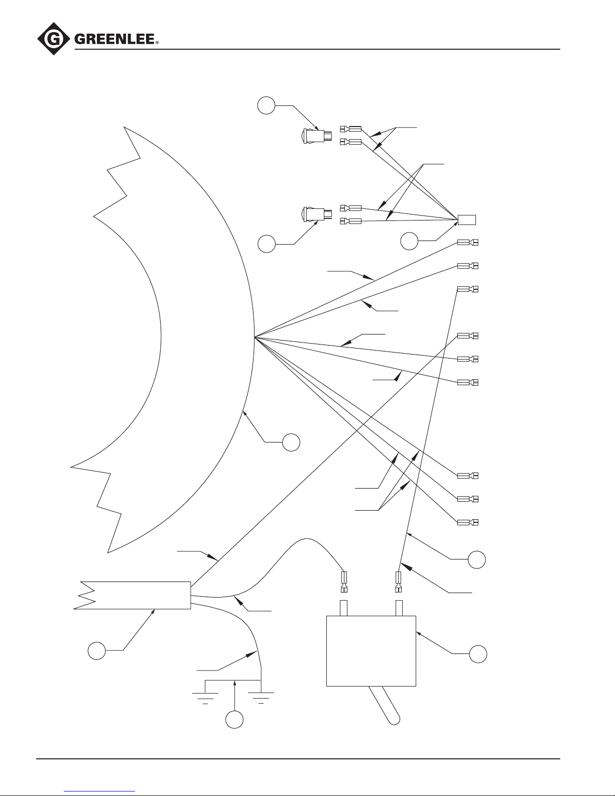
Parts List
Key Part No. Description Qty
1 50035690 Cover......................................................................................................... 1
2 50297082 Guard, circuit breaker ............................................................................... 1
3 90522036 Screw, machine, #6 – 32 x .250 round head............................................. 2
4 50035622 Power cord................................................................................................ 1
5 90541243 Bushing, strain relief.................................................................................. 1
6 91862639 Nut, lock , 1/2" conduit ............................................................................ 1
7 90516451 Screw, cap, #10 – 32 x .500 socket button head .................................... 3
8 90507509 Washer, lock, #10, internal tooth............................................................... 3
9 90516583 Nut, hex, #10 – 32..................................................................................... 3
10 90516559 Screw, thread-forming, #10 – 16 x .500.................................................. 16
11 91863856 Circuit breaker, 20 amp ............................................................................. 1
12 50046438 Transformer ............................................................................................... 1
13 50035738 Box............................................................................................................ 1
14 50035762 Plate, identication.................................................................................... 1
15 90530012 Rivet, pop, .125......................................................................................... 4
16 50035754 Foot........................................................................................................... 4
17 90512650 Screw, cap, 1/4 – 20 x .750 socket head................................................. 4
18 52027081 Screw, cap, 3/8 – 24 x 2.00 hex head....................................................... 1
19 90526805 Nut, hex, 1/4 – 20...................................................................................... 4
20 50047817 Control assembly (includes the next six items)......................................... 1
20A 90550501 Standoff, threaded, #6 – 32 x .500............................................................ 2
20B 50046942 Subplate.................................................................................................... 1
20C 91866448 Support, circuit board ............................................................................... 4
20D 50046390 Circuit board ............................................................................................. 1
20E 90537246 Washer, lock, #6, internal tooth................................................................. 4
20F 90522036 Screw, machine, #6 – 32 x .250 round head............................................. 4
21 90550510 Washer, lock, 15/32 internal tooth ............................................................ 2
22 91868904 Ring, locking ............................................................................................. 2
23 91868890 Switch ....................................................................................................... 2
24 90524349 Nut, hex, #8 – 32....................................................................................... 3
25 90516494 Washer, lock, #8, internal tooth................................................................. 3
26 90514408 Screw, machine #8 – 32 x .375 round head.............................................. 3
27 91868548 Receptacle, female ................................................................................... 1
28 91864747 Lamp, red neon......................................................................................... 1
29 91868866 Lamp, amber neon.................................................................................... 1
30 50035746 Guard, switch............................................................................................ 1
The following items are not illustrated:
31 50046365 Wire unit, receptacle, black....................................................................... 1
32 50046373 Wire unit, receptacle, white....................................................................... 1
33 50046403 Wire unit, lamps ........................................................................................ 1
34 50046411 Wire unit, switches.................................................................................... 1
35 50046420 Wire unit, breaker...................................................................................... 1
36 50036190 Wire unit, receptacle, relay........................................................................ 1
37 500 49879 Wire unit, ground bond ............................................................................. 1
38 50035800 Decal ......................................................................................................... 1
39 50303929 Decal, damp warning ................................................................................ 1
Service Kits:
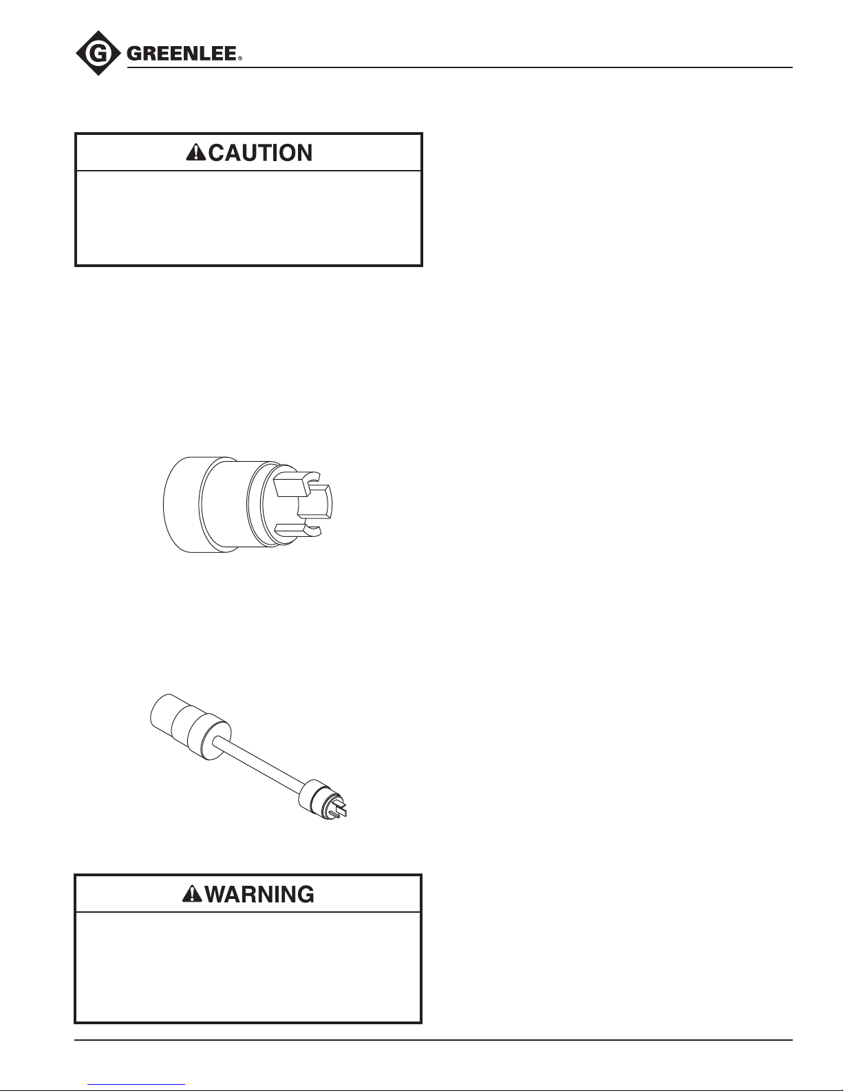
50048848 Adapter cord and plug kit
50062115 Adapter cord kit
50062123 Electric plug kit