Greenlee Textron Inc. / Subsidiary of Textron Inc. 4
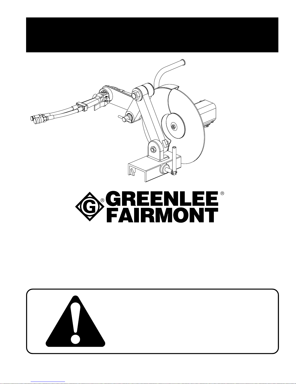
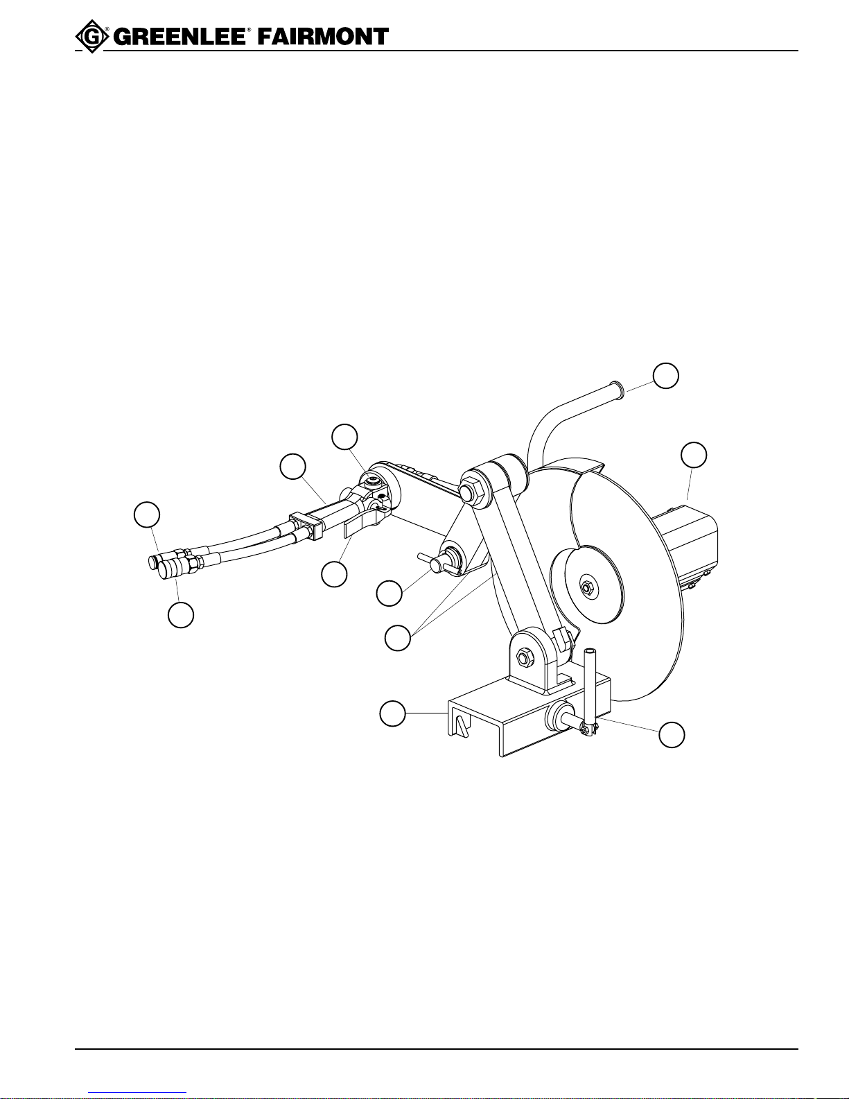
H4645 Rail Cut-Off Saw
4455 Boeing Dr., Rockford, IL 61109-2988 815/397-7070
• The owner of this tool must be certain that all
users of this tool are adequately trained to safely
use this tool in compliance with appropriate
industrial codes or standards.
• Use all appropriate and applicable personal safety
equipment as required, such as: Safety shoes,
hard hat, safety glasses, face shield, aprons and
gloves, etc.
• Protect surroundings from sparks, swarf, and
flying particles. Sparks could ignite clothing,
grass, etc.
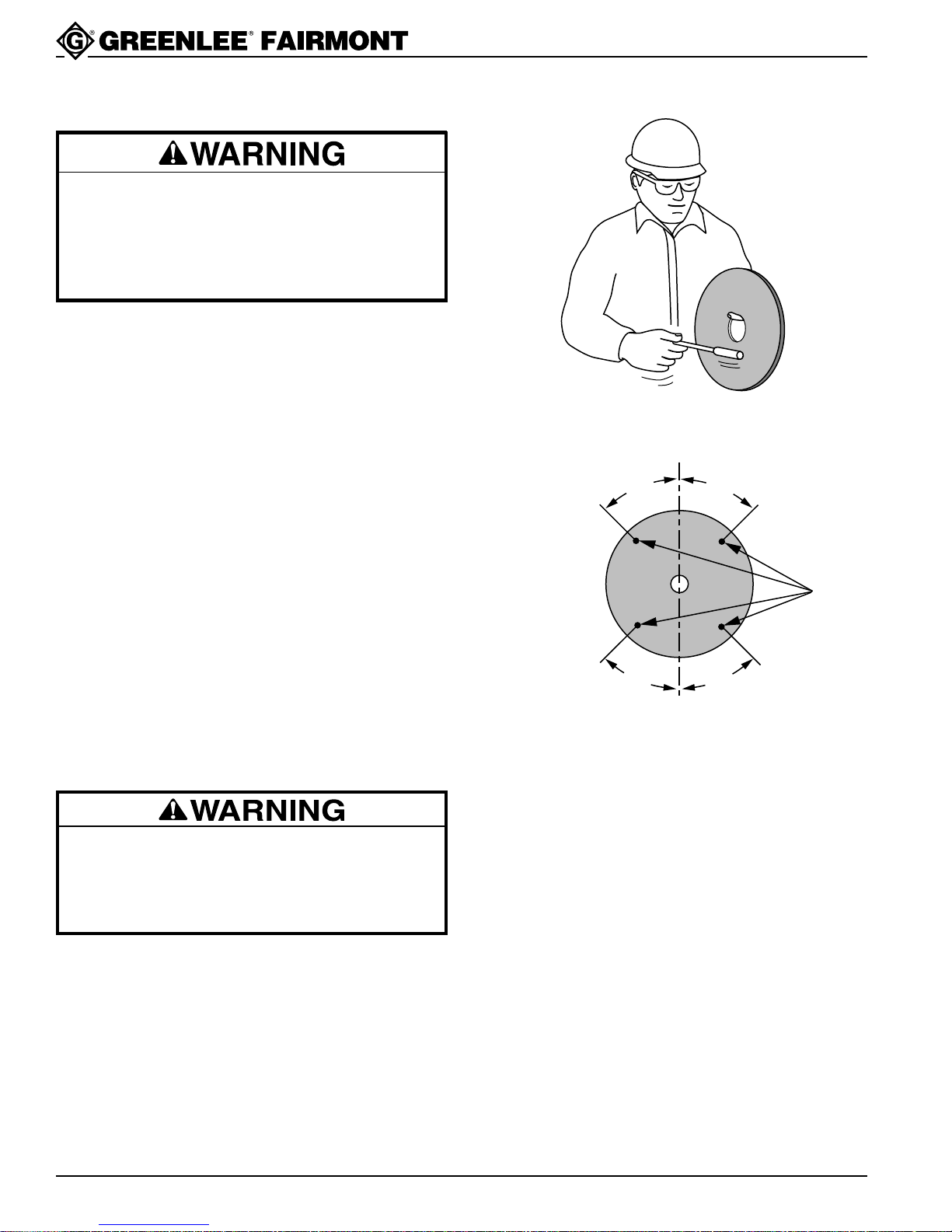
• Disconnect tool from power source before
changing or examining blade.
• Disconnect tool from power source before
disassembly, performing maintenance, and
makingadjustments.
•
Do not disconnect tool, hydraulic components, lines
or fitting while hydraulic power source is running
and/or if hydraulic fluid is hot. Exposure to hot
hydraulic fluid can cause serious personal burns.
Failure to observe these warnings could result in
severe injury or death.
Always wear safety glasses when
operating this tool.
Failure to observe this warning may
result severe injury.
Skin Injection Hazard:
High pressure oil easily punctures
s
kin causing serious injury, gangrene
or death. If injured seek medical
help immediately to remove oil.
Do not use fingers or hands to
check for leaks.
Depressurize hydraulic system
beforeservicing.
• Use this tool for the manufacturer’s intended
purpose only.
• Inspect hydraulic hoses and couplings every
operating day. Repair or replace if leakage,
cracking, wear, or damage is evident.
• Observe and follow all safety rules and regulations
for the job.
• Do not transport or store rail saw with the blade
mounted.
• Do not grind on the side of a cutting wheel.
• Follow the wheel manufacturer’s instructions for
storage of abrasive cutting wheels.
Failure to observe these precautions could result in
injury or property damage.
Note: Keep all decals clean and legible. Replace
decals when necessary with new decals
listed in Parts section of this manual.
• Do not use power head without rail clamp
assembly. Read and understand the proper
setup procedure for the rail clamp assembly.
• Use the rail cut-off saw for cutting rail only.
• Do not use the rail saw without the wheel guard.
•
Use only 1/8"–5/32" thick, high-strength,
reinforced, abrasive cut-off wheels rated for at
least 3800 rpm meeting ANSI B7.1-1978 Class 10.
• Do not use an abrasive cutting wheel which has
cracks, chips, gouges, or evidence of damage
from handling or storage.
• Do not contact the cutting wheel when it is
rotating.
• Keep all parts of the body clear of moving parts of
the tool when connected to a power source or in
operation.
• Do not stand in the path of the cutting wheel.
• Do not place any part of the body over the rotating
cutting wheel.
• Make sure all bystanders are clear of the work
area when handling, starting and operating tool.
• Maintain a firm grip on tool, using both hands at
all times.
Failure to observe these warnings could result in
severe injury or death.