GREENoneTEC Sunpad User manual

Instruções de montagem
Instrucción de montaje
Notice de montage
Istruzioni di montaggio
Instruction manual
EN
IT
FR
ES
PT
FOLLOW
THIS
MANUAL
Distributed by:
Eco-$mart, Inc.
941.376.8484 ph
www.eco-smart.com
Eco-$mart, Inc. is a
Service-Disabled Veteran
Owned Business

2
PTESFRITEN
20°
30° 5-45°
Contents
Indice
Table des matières
Contenido
Índice
Safety information................................................................................................................................................................. 4
General information ............................................................................................................................................................. 5
Operating instructions ......................................................................................................................................................... 8
Warranty and Liability........................................................................................................................................................... 11
Technical data........................................................................................................................................................................ 44
Specications for Water Quality.......................................................................................................................................... 45
Hydraulic diagram ................................................................................................................................................................ 46
Transport note....................................................................................................................................................................... 47
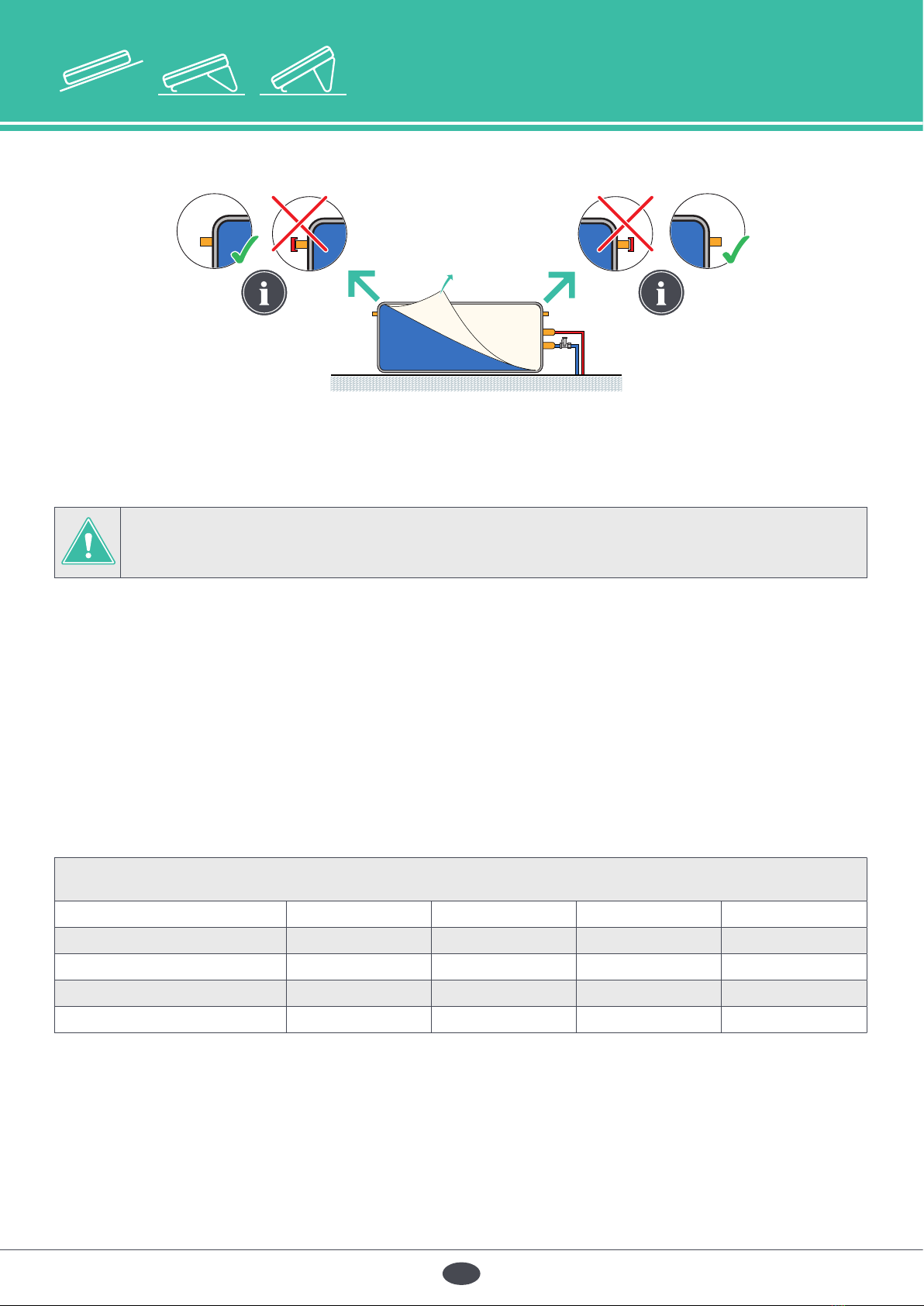
Collector inclination min. 5° - max. 45°.............................................................................................................................. 48
Filling Instructions of the system......................................................................................................................................... 49
Hydraulic installation examples / Pressure drop .............................................................................................................. 50
Explanation of Symbols - Tools required ........................................................................................................................... 51
Overview of materials .......................................................................................................................................................... 52
Important information - Drilling plan ................................................................................................................................. 53
Flat Roof Installation ............................................................................................................................................................. 54
On-roof mounting system, parallel..................................................................................................................................... 60
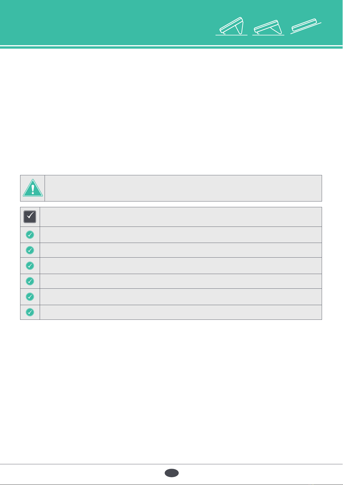
Checklist for rst start-up..................................................................................................................................................... 64
Yearly maintenace of the SUNPAD system........................................................................................................................ 74
EN
Avvertenze per la sicurezza ................................................................................................................................................. 12
Informazioni generali ........................................................................................................................................................... 13
Istruzioni per l‘uso................................................................................................................................................................. 16
Garanzia e responsabilità .................................................................................................................................................... 19
Dati tecnici............................................................................................................................................................................. 44
Dati sulla qualità dell’acqua................................................................................................................................................. 45
Schema idraulico .................................................................................................................................................................. 46
Indicazioni per il Trasporto .................................................................................................................................................. 47
Inclinazione del collettore min. 5° - max. 45°.................................................................................................................... 48
Riempire il sistema................................................................................................................................................................ 49
Esempi di installazione idraulica / Perdita di carico ......................................................................................................... 50
Spiegazione dei simboli - Attrezzi necessari .................................................................................................................... 51
Panoramica dei materiali ..................................................................................................................................................... 52
Informazioni importanti - Piano di foratura ....................................................................................................................... 53
Montaggio su tetto piano.................................................................................................................................................... 54
Sistema di montaggio su tetto, in parallelo....................................................................................................................... 60
Lista di controllo per la messa in funzione ........................................................................................................................ 66
Controllo annuale del sistema a SUNPAD......................................................................................................................... 75
IT
Instructions de sécurité........................................................................................................................................................ 20
Renseignements d‘ordre général ....................................................................................................................................... 21
Mode d‘emploi...................................................................................................................................................................... 24
Garantie et responsabilité ................................................................................................................................................... 27
Données techniques ............................................................................................................................................................ 44
Informations concernant la qualité de l’eau ...................................................................................................................... 45
Schéma hydraulique............................................................................................................................................................. 46
Indications pour le transport ............................................................................................................................................... 47
Inclinaison du capteur min. 5° - max. 45° .......................................................................................................................... 48
Instruction pour le remplissage .......................................................................................................................................... 49
Exemples d‘installation hydraulique / Perte de charge .................................................................................................. 50
Explication des symboles - Outillages nécessaires.......................................................................................................... 51
Vue d’ensemble du matériel................................................................................................................................................ 52
Renseignements importants - Plan de forage................................................................................................................... 53
Montage sur toit plat ........................................................................................................................................................... 54
Système de montage sur toiture en parallèle................................................................................................................... 60
Points à vérier lors de la mise en service ......................................................................................................................... 68
Entretien annuel du système de SUNPAD......................................................................................................................... 76
FR

3
PTESFRITEN
30°
20°
5-45°
Contents
Indice
Table des matières
Contenido
Índice
ES Advertencias de seguridad .....................................................................................................................................................28
Información general .................................................................................................................................................................29
Instrucciones de uso.................................................................................................................................................................32
Garantía y responsabilidad......................................................................................................................................................35
Datos técnicos...........................................................................................................................................................................44
Datos sobre la calidad del agua .............................................................................................................................................45
Esquema hidráulico..................................................................................................................................................................46
Indicaciones para el Transporte..............................................................................................................................................47
Inclinación del colector mín. 5° - máx. 45° ............................................................................................................................48
Llenado del sistema..................................................................................................................................................................49
Ejemplos de instalaciones hidráulicas / Pérdida de presión...............................................................................................50
Lista de materiales - Herramientas necesarias......................................................................................................................51
Vista general de los materiales ...............................................................................................................................................52
Informaciones importantes - Plano de perforación..............................................................................................................53
Montaje en tejado plano .........................................................................................................................................................54
Sistema de montaje sobre tejado en paralelo......................................................................................................................60
Lista de vericación para la puesta en marcha inicial..........................................................................................................70
Mantenimiento anual del sistema de SUNPAD.....................................................................................................................77
PT Indicações de segurança.........................................................................................................................................................36
Informações gerais ...................................................................................................................................................................37
Instruções de operação ........................................................................................................................................................... 40
Garantia e Responsabilidade..................................................................................................................................................43
Dados técnicos..........................................................................................................................................................................44
Especicações para qualidade da água................................................................................................................................45
Diagrama hidráulico.................................................................................................................................................................46
Nota de transporte ...................................................................................................................................................................47
Inclinação do colector mín. 5° - máx. 45° ..............................................................................................................................48
Preenchimento do sistema......................................................................................................................................................49
Exemplos de instalação hidráulica / Perda de pressão .......................................................................................................50
Explicação dos símbolos - Ferramenta necessária...............................................................................................................51
Materiais gerais......................................................................................................................................................................... 52
Informações importantes - Plano de perfuração..................................................................................................................53
Instalação em telhado plano...................................................................................................................................................54
Sistema de montagem em telhado, paralelo........................................................................................................................60
Lista de vericação para o comissionamento inicial............................................................................................................ 72
Manutenção anual do sistema SUNPAD................................................................................................................................78
691100455.2 / version 2022-08

4
EN
20°
30° 5-45°
Safety information
Avvertenze per la sicurezza
Instructions de sécurité
Advertencias de seguridad
Indicações de segurança
Safety precautions: Before commencing mounting work on
roofs, it must be ensured in all cases that the non- personal
fall protection and fall-arrest systems required by DIN 18338
(Roof Covering and Roof Sealing Works) and DIN 18451
(Scaffolding Works) are in place. See also Builders‘ Protec-
tion Ordinance [Bauarbeiterschutzverordnung], Federal Law
Gazette 340/ 1994, paragraphs 7-10! Other country-speci c
regulations must be observed!
Safety harnesses should be xed above the users whenever
possible. Safety harnesses should only be fastened to suf ci-
ently load-bearing structures or xing points!
If non-personal fall protection or fall-arrest systems cannot
be installed for technical reasons, all personnel must be
secured by means of suitable safety harnesses!
Never use damaged ladders (e.g., wooden ladders with split
runners or rungs, or bent or buckled metal ladders). Never
try to repair broken runners, rungs or steps on wooden
ladders!
Only use safety harnesses (safety belts, lanyards and straps,
shock absorbers, fall arresters) that were tested and certi ed
by authorized testing bodies.
Ensure that ladders are put up safely. Observe the correct
leaning angle (68° - 75°). Prevent ladders from sliding, falling
over or sinking into the ground (e.g. using wider feet, feet
suited to the ground or hooking devices).
If non-personal fall protection or fall-arrest systems are
not provided, working without the use of suitable safety
harnesses may lead to falls from heights and therefore cause
serious or lethal injuries!
Only lean ladders against secure points. Secure ladders in
traf c areas by suitable cordoning.
Ladders not properly secured against sinking in, sliding or
falling over may lead to dangerous falls! Contact with live electric overhead cables can be lethal.
Whenever you are near live overhead electric cables where
contact is possible, only work if:
–it is ensured that they are voltage-free and this is secu-
red for the duration of work.
–the live parts are secured by covering them or cordo-
ning them off.
–the prescribed safety distances are maintained.
Voltage radius:
1 m ................voltages up to 1000V
3 m ................voltages from 1000V to 11000V
4 m ................voltages from 11000V to 22000V
5 m ................voltages from 22000V to 38000V
> 5 m in case of unknown voltages
Wear protective goggles when drilling and handling collec-
tors!
Wear safety shoes when carrying out installation work!
Wear cut-proof safety gloves when mounting
collectors!
Only the heat transfer medium speci ed may be used! Wear a helmet when carrying out installation work!
EN

5
EN
30°
20°
5-45°
General information
Informazioni generali
Renseignements d‘ordre général
Información general
Informações gerais
General Information
We are delighted that you have chosen our product. With this high-quality, high-performance product, you have made an
excellent selection. We wish you successful operation and many sunny days. Please read this manual carefully before installation
and commissioning, as it contains important information for proper installation and for safety.
After the commissioning has been successfully completed, the assembly instructions must be handed over to the end customer.
We would like to point out that proper function can only be guaranteed if: 1) you have annual maintenance carried out by quali-
ed experts, 2) the instructions mentioned in this manual and 3) the stated operational recommendations are observed,
and 4) the original accessories or spare parts are used.
1.1. Expert Persons (assembly, commissioning, maintenance and troubleshooting)
"Expert persons" are exclusively those persons who are quali ed and certi cated installers (in the case of electrical components:
Electricians) with current trade registrations. All the activities listed in these installation instructions must, without exception,
be carried out by these expert persons.
1.2. General Storage and Transport Instructions
The system components must not be stored unprotected outdoors; especially the system connections and the aeration/ventilation
openings must be protected from water ingress and contamination, such as dust, etc.
The system or the storage tank must not be lifted up by the connectors or screw threads; avoid impacts and mechanical infl u-
ences on the system components, in particular on the solar glass, system back panel, pipe connections and storage tank sheath.
1.3. General Installation Instructions
Installation may only be carried out by a quali ed professional. The instructions provided here are directed at quali ed
professionals only. The supplied materials must be used for installation. Prior to installing and operating the SUNPAD system,
familiarise yourself with the locally applicable standards and regulations.
Structural Engineering Aspects
The system may only be installed on a roof surface or substructure with suf cient load-bearing capacity. The static load-bear-
ing capacity of the roof or substructure must be checked in accordance with local and regional stipulations on site prior to the
assembly of the systems. In particular, it is important to check whether the quality of the (wooden) substructure is suf cient to
ensure the durability of the screw connections for attaching the system mounting apparatus.
The on-site inspection of the system (system and attachment apparatus) as per EN 1991 and/or country-speci c regulations is
particularly important in areas prone to high winds.
When doing this, you need also to investigate all the peculiarities of the erection location (prevailing winds (foehn),
venturi effects, eddies, etc.) that may lead to locally increased load.
Information regarding inclined roofs:
The assembly of a SUNPAD system constitutes an intervention in an (existing) roof. Roof cladding such as tiles, shingles and
slate, attics with a special construction or that are used for residential purposes, and roof pitches that are below the minimum
recommended value require (in relation to the cladding) additional constructions measures to protect against the penetration
of water as a result of wind force and driving snow. This might include sub-roof membranes, for example. When selecting the
installation site, note that the maximum permissible loads due to wind forces must not be exceeded. To prevent impermissible
wind loads, the collectors must not be installed at the edge of a roof (e/10 edge zones as per EN 1991, but with a minimum gap
of 1 m). In particular, in the case of elevated structures, the top of the system must not protrude above the roof ridge.
Information regarding at roofs:
The installation of a SUNPAD system constitutes an intervention in an (existing) roof. Attics with a special construction or that are
used for residential purposes and roof pitches that are below the minimum recommended value require (in relation to the clad-
ding) additional construction measures to protect against the penetration of water as a result of wind force and driving snow.
This might include sub-roof membranes, for example. When selecting the installation site, note that the maximum permissible
loads due to wind forces must not be exceeded. To prevent impermissible wind loads, the panels must not be installed at the
edge of a roof (e/10 edge zones as per EN 1991, but minimum gap of 1 m). In the case of larger system elds, we recommend
that you mount the SUNPAD system on a separate bearing structure made from steel pro les.

6
EN
20°
30° 5-45°
Lightning Protection
As per the stipulations of Lightning Protection Standard EN 62305 Parts 1-4, the SUNPAD system must not be connected to the
building's lightning protection. Beyond the scope of validity of this standard, country-speci c requirements must be observed.
A safety gap of at least one metre from any adjacent conductive object must be maintained. In the case of installations on top
of existing metal substructures, an authorised and quali ed electrician must generally be consulted. To enable equipotential
bonding of the building, the metallic conductor pipes of the solar/water circuit and all of the system housing/ xtures must be
connected to the main equipotential busbar by an authorised and quali ed electrician in accordance with EN 60364 and/or
country-speci c requirements.
General Important System Information
The SUNPAD system is a two-circuit system. The SUNPAD system forms a closed circuit (process water circuit) with the heat
exchanger of the storage tank. This circuit is completely separate from the solar circuit (storage tank). The SUNPAD system or
the SUNPAD-E system offers appropriate performance only when installed in frost-free areas. If the temperature falls below 0 °C
for more than 18 consecutive hours or -5 °C for more than six consecutive hours, the domestic hot water circuit of the SUNPAD
system must be drained.
SUNPAD-E In this SUNPAD-E system, an electric immersion heater can be installed into the solar water circuit.
The system storage tank is already prepared for its installation as standard. An appropriate electric
immersion heater is available as a retro t kit in the optional scope of supply of the product.
The hot and cold water lines in the process water circuit are not protected from freezing by the elec-
tric immersion heater. When installing, appropriate insulation and trace heating for the pipes must
be provided.
The frost tolerance limits are based upon an assumed set of environmental conditions. Extended periods of cold weather,
including ambient air temperatures below the speci ed limit of -5°C, may cause freezing in exposed parts of the system. It is the
owner’s responsibility to protect the SUNPAD system in accordance with the manufacturer’s instructions if the air temperature is
anticipated to approach the speci ed frost tolerance limits.
Protect all water pipes from freezing. If the SUNPAD system is not completely drained, the warranty will become void.
After initial commissioning and in seasons with strong outside temperature fl uctuations, condensation may form in the SUNPAD
system. However, this condensation disappears after a few hours of sunlight.
A thermal mixer, where the required water temperature can be set, must always be installed at the
hot water outlet as scald protection. The safety over-pressure valve provided must be installed on
the cold water connection to the SUNPAD system in order to limit overpressure in the water circuit.
System Alignment
For the installation of the SUNPAD system, a suitable place without shade (e.g. trees, buildings) is required throughout the year.
For optimum function of the SUNPAD system, it should be installed facing south in the northern hemisphere and facing north in
the southern hemisphere, if possible. Mounting vertically to the rst is prohibited; the system must be mounted in the horizontal
orientation. Please note the appropriate installation instructions (
see page 48).
System inclination
The SUNPAD system is suitable for an inclination of at least 5° to a maximum of 45° and may only be mounted horizontally
(+/-5°). Other installation angles are not permitted, as this will cause irreparable damage to the solar storage tank.
System pressures
The maximum operating pressure in the cold water supply must always be limited to 10 bar; if necessary, a corresponding/
suitable pressure reducer must be installed. The solar storage tank of the SUNPAD system must be kept depressurised; one of
the two lling openings above (see sketch) must remain open due to the risk of irreparable damage to the solar storage tank.
The maximum operating overpressures speci ed on the storage tank identi cation plate must never be exceeded. The safety
valve provided must always be installed in the relevant connection on the storage tank to limit the overpressure in the process
water circuit (see sketch).
General information
Informazioni generali
Renseignements d‘ordre général
Información general
Informações gerais

7
EN
30°
20°
5-45°
Connection Diagram:
Connections, Joints and Piping
Depending on the application, the SUNPAD system can reach temperatures of up to 95 °C, which can lead to injuries (e.g. scalding).
As a result, a suitable thermal mixer must always be installed downstream of the hot water outlet to limit the process water tem-
perature to max. 60 °C.
CAUTION: Only use pipes and ttings that are suitable for sanitary facilities and that can
withstand temperatures of at least 100 °C.
Connections and Piping
The SUNPAD system must be connected to the connection piping (3/4
" external thread) in a fl at-sealing and only the seals
intended and provided for this purpose may be used. It is important to make sure that the fl at gaskets are properly seated.
Please pay special attention to the hydraulic diagram for the cold water and hot water connections in the manual.
When the connections are tightened up, pliers or other wrenches must be used for holding (locking), in order to prevent the
connector from being damaged. If no fl exible tubes are available for use as connection elements, make sure that the connecting
piping allows for appropriate precautions to compensate for the thermal expansion caused by temperature fl uctuations, e.g.
suitable expansion elbows or fl exible piping. In the connecting lines, tension relief must be provided (see sketch).
Insulation of the System Circuit Pipe
The pipes must be insulated with a suitable UV-resistant material to reduce heat loss and protect the pipes from freezing.
To ensure perfect functionality, make sure that the valves are not insulated. The process water connection must be established in
accordance with DIN 1988 and DIN 4753 (country-speci c regulations must be observed!).
Yield prognosis
Indicators for the performance of solar systems without auxiliary heating and of solar preheating systems on an annual basis
for a volume requirement of 140 l/d
Location (latitude) Qd / MJ QL / MJ fsol / % Qpar / MJ
Stockholm (59,6° N) 7821 2652 - 34
Würzburg (49,5° N) 7506 2857 - 38
Davos (46,8° N) 8483 3784 - 45
Athens (38,0° N) 5834 3816 - 65
General information
Informazioni generali
Renseignements d‘ordre général
Información general
Informações gerais

8
EN
20°
30° 5-45°
Instructions for Commissioning and Filling the System
The SUNPAD system is delivered with a protective lm over the solar glass. This protective lm blocks sunlight and must not
be removed until the system has been lled. For safety reasons (risk of burning and scalding), the lling of the SUNPAD system
must be carried out exclusively with the protective lm applied. This prevents heating of the solar system during installation.
Premature removal of the protective lm could cause thermal damage to important system components due to overheating of
the product by direct sunlight. To protect the materials from excessive thermal load, the lling and commissioning of the system
should be carried out immediately after assembly; apart from that, the system must be protected against direct sunlight.
The SUNPAD system must be lled no later than two weeks after assembly. After initial commissioning and in seasons with
strong outside temperature fl uctuations, condensation may form in the SUNPAD system.
However, this condensation disappears after a few hours of sunlight.
Make sure that the maximum operating pressure stated on the type plate or in the installation instructions is not exceeded.
Check to make sure that all safety components have been installed in accordance with the hydraulic diagram before you open
the water supply and ll the system before initial start-up.
Filling the System
CAUTION:
If you do not follow these instructions, the solar storage tank will be irreparably damaged!
CHECK The following procedure must be observed when lling the system:
Connect the lling opening of the solar circuit (solar storage tank) to the cold water pipe according to the
hydraulic diagram.
Open the cold water shut-off valve.
Fill the solar storage tank up to the water outlet on the opposite side (the storage tank is completely lled).
Now connect the cold/hot water pipe to the SUNPAD system according to the hydraulic diagram.
Open the cold water shut-off valve to ll the process water circuit, and then open the hot/cold tap in the house
to allow the remaining air to escape from the system.
Carefully inspect the system for leaks.
System in Unused Condition/Periods Without Hot Water Consumption
If the SUNPAD system is not used for a period of two weeks, e.g. during holidays, the SUNPAD system should remain lled
and then be thoroughly fl ushed before rst use (process water circuit) in order to clean possible contamination from the heat
exchanger. If the SUNPAD system is not used for a longer period of time (e.g. longer summer holidays), the system must be
covered with a light-refl ecting cloth or a light-refl ecting lm to avoid damage caused by overheating.
Operating instructions
Istruzioni per l‘uso
Mode d‘emploi
Instrucciones de uso
Instruções de operação

9
EN
30°
20°
5-45°
Maintenance Instructions
Maintenance work may only be carried out by expert trained personnel. The SUNPAD system must be maintained and
documented at least annually in accordance with the points described (see the warranty conditions). In case of very low water
consumption or for longer periods of non-use, the maintenance interval must be shortened.
CHECK
For annual maintenance and inspection work on the SUNPAD system,
the following points must be taken into account:
Fill the water level; observe the "Filling the system" section in this manual (see page 49)
ATTENTION: If the system is operated with antifreeze, it must be re lled!
Check for damage to the system
Check for leakage on the connectors
Check for a rm seat of the connecting screws to the roof
Check the insulation on the supply/drain line (process water circuit)
CHECK Additionally for SUNPAD-E:
Check for damage to electrical lines
Check for leaks in the e-cartridge area
ATTENTION — DANGER OF SCALDING! WARNING: WATER MAY BE DISCHARGED AT VERY HIGH
TEMPERATURES. TO AVOID SCALDING, EXERCISE MAXIMUM CAUTION WHEN DRAINING THE
HOT WATER FROM THE SUNPAD SYSTEM. DON'T TOUCH THE HOT PIPES!
To replace and maintain the electric immersion heater, ensure that the hot water temperature in the solar storage tank is not
above 45 °C. One day before the start of work, the SUNPAD system should be protected from sunlight with a cover.
We also recommended repair work be carried out only in the early morning hours.
Increasing the ef ciency
To increase the ef ciency of the SUNPAD system, observe the following recommendations:
1. If possible, use the hot water in the evening (e.g. for showering)
2. Use a timer (including overnight shutdown) in connection with the original heating element to prevent unnecessary
heat losses
3. A volume fl ow of 10 lt. / min is recommended for optimum system performance, higher fl ow rates can lead to rapid
hot water consumption.
Instructions on Using the Heating Element
(included in the scope of supply of SUNPAD-E)
Only the original heating element from the manufacturer may be used to prevent damage or destruction of the SUNPAD system.
The electric heating element is optionally available as an accessory.
Safety Instructions for Installing the Electric Immersion Heater
For the installation of the electric immersion heater, you must ensure that the SUNPAD system is protected from sunlight.
The electric immersion heater, available as an option, may only be integrated in the SUNPAD system by expert personnel.
Operating instructions
Istruzioni per l‘uso
Mode d‘emploi
Instrucciones de uso
Instruções de operação

10
EN
20°
30° 5-45°
Operating instructions
Istruzioni per l‘uso
Mode d‘emploi
Instrucciones de uso
Instruções de operação
Maintenance of the system
The system must be inspected visually, once a year, for any damage, leaks and contamination. Condensate can form in the sys-
tem after commissioning and during times of the year with strong outdoor temperature fl uctuations. This condensate disappears
however after a few hours exposure to sunlight.
Maintenance of anti-re ective glass (AR glass)
To ensure and preserve the best possible performance of a collector with increased transmission glass (anti-refl ective glass or
AR glass for short), the following points in particular should be observed.
USE
…
•
Clean lifting gear, suction holders, and gloves
•
A cover for the glass vacuum lifter (material: Tyvek; replace when dirty)
•
Do not use the glass surface as a place to deposit installation material or other objects!
ATTENTION:
Clear the AR glass only with plain water or slightly soapy water!
The following can damage the anti-re ective coating and thus prevent the system from achieving
its full performance!
AVOID
...
•
Getting ngerprints or stains on the glass
•
Using leather gloves
•
Contact with silicone, oil, grease, and any other thick, hydrophobic substances
•
Cleaning aids such as car polish, fl uoric acid, wire wool, wire brushes, polishing cloths,
•
Scouring powder, and fabrics containing metal yarn
•
Mechanical cleaning methods such as scrubbing, stripping, and high-pressure cleaning

11
EN
30°
20°
5-45°
Warranty and Liability
A warranty entitlement exists only if:
•
an inspection is performed on arrival of the goods that reveals obvious defects, which are immediately communicated to us.
•
the installation, commissioning and maintenance of the products by a quali ed expert (heating system technician or installer).
has been properly accomplished in accordance with the speci cations in the installation instructions, taking into account the
applicable standards and directives.
•
after noti cation of a product defect, we or our representative is provided immediate access for on-site inspection and
testing, repeated if necessary, and the affected products are immediately sent back to us at our request and expense.
•
there are written con rmations by a quali ed expert available regarding the correct commissioning and annual
inspection and maintenance.
We accept no liability for defects or damage:
•
to parts that have not been supplied by the manufacturer, as well as wear parts, such as valves, immersion heaters, etc.
•
for corrosion, deposits, frost (ice formation), glass breakage, mechanical stress, normal wear and ageing, environmental
infl uences (e.g. near coastal or industrial areas), improper repairs, maintenance or modi cations, or force majeure,
whether caused by transport/shipping/storage.
GREENoneTEC
provides a warranty for the freedom from defects of the delivered SUNPAD system for a period of 5 years.
Accessories such as valves and heating element have a warranty period of 2 years. The warranty period starts with the produc-
tion date noted on the type sticker. Prerequisites for the warranty claim are assembly, commissioning and maintenance by a
specialist company according to the provided installation instructions, as well as proper documentation.
Excluded from the warranty are defects and damage caused by corrosion (water limits see installation instructions), limescale
deposits, frost, (system) overpressure, broken glass as well as errors in components that are not supplied by
GREENoneTEC.
We accept no liability for unintended use or unauthorised changes to the assembly components and any resulting consequenc-
es, as well as non-observance of the assembly instructions.
Unless otherwise stipulated in this warranty agreement, the current terms and conditions of business of
GREENoneTEC
(www.greenonetec.com) apply.
The instructions described in the assembly manual refer to the current state of development, while the illustrations used are
symbolic representations. These installation instructions contain proprietary information that is protected by copyright.
Due to possible typesetting and printing errors and the need for technical changes, no liability can be assumed for the correct-
ness of the content of the assembly instructions.
CAUTION: Guarantee claims are only valid if assembly, commissioning and documented
maintenance have been properly performed.
General Usage Instructions
All the details and instructions in these installation instructions relate to the current level of development.
Please always use the installation instructions provided. Illustrations used are symbolic photos. Due to possible typographical
and printing errors, but also due to the necessity of continuous technical modi cations, we ask for your understanding that
we cannot accept any liability for the correctness of content. We refer to the applicability of the general terms and conditions
in their currently valid form. These installation instructions contain proprietary information that is protected by copyright. We
reserve the rights of and the right to make changes to these installation instructions.
IMPORTANT INFORMATION: Dear customer, in order to guarantee you the full warranty
period of 5 years on the system and 2 years on accessories it is mandatory required to
register your product(s)! You will nd the registration QR code on the page “Checklist for
the rst start-up” at the back of this manual. Thank you!
Warranty and Liability
Garanzia e responsabilità
Garantie et responsabilité
Garantía y responsabilidad
Garantia e Responsabilidade

44
PTESFRITEN
20°
30° 5-45°
Gross area [m²]
Supercie lorda
Surface brute
Supercie bruta
Área bruta
2,05
Net area [m²]
Supercie netta
Surface nette
Supercie neta
Área líquida
1,68
Dimension L / W / H [mm]
Dimensioni
Dimension
Dimensiones
Dimensão
2220 x 920 x 198
Weight empty [kg]
Peso a vuoto
Poids à vide
Peso en vacío
Peso vazio
72
Connection
Connessioni
Connexions
Conexiones
Conexões
¾"
Tank capacity [l]
Contenuto del serbatoio
Contenu de mémoire
Capacidad del tanque
Conteúdo de memória
150
Capacity heat exchanger [l]
Grandezza dello scambiatore di calore
Capacité de l‘échangeur de chaleur
Capacidad del intercambiador de calor
Capacidade do trocador de calor
9,2
Compressive strength/
heat exchanger [bar]
Resistenza alla compressione/
scambiatore di calore
Résistance à la compression/
l‘échangeur de chaleur
Presión máxima del
intercambiador de calor
Resistência à compressão/
trocador de calor
10
Technical data
Dati tecnici
Données techniques
Datos técnicos
Dados técnicos
2220
920
920
198
586
995
20°
665
893
30°
920
198

45
PTESFRITEN
30°
20°
5-45°
Specications for Water Quality
Dati sulla qualità dell’acqua
Informations concernant la qualité de l’eau
Datos sobre la calidad del agua
Especicações para qualidade da água
Water quality
Qualità dell‘acqua
Composants de l’eau
Calidad del agua
Substâncias na água
Tank
Serbatoio
Réservoir
Tanque
Tanque
Heat exchanger
Scambiatore di calore
Échangeur de chaleur
Intercambiador de calor
Permutador de calor
T WTS WTP
pH value
Valore pH - Valeur du pH - Valor de pH - Valor de pH 7 - 9 *
Total hardness [°dH]
Durezza totale - Titre hydrotimétrique total - Dureza total - Dureza total
6 - 15
> 5
Chlorides [mg/l]
Cloruri - Chlorures - Cloruro - Cloretos < 100 < 250 < 1000
Free chlorine [mg/l]
Cloro libero - Chlore libre - Cloro libre - Sem cloro < 0,2 < 0,5
Sulfate [mg/l]
Solfato - Sulfate - Sulfato - Sulfato < 100 < 250
Conductibility [μS/cm - 25°C]
Conductivité - Conductabilidad - Conductabilidad - Condutividade 650 2500
TO AVOID SYSTEM FAILURE AND DAMAGES, ASSURE THAT THE WATER QUALITY FALLS WITHIN
THE RANGE OF THE WATER VALUES AS WRITTEN ABOVE. If the water values are out of the speci-
ed limiting values, the warranty is void. Installation is performed at the user’s own risk.
LA GARANZIA SCADE SE SI UTILIZZA IL SISTEMA SUNPAD UTILIZZANDO ACQUA CHE NON RIENTRA
NELL‘INTERVALLO DEI VALORI DELL‘ACQUA SOPRA INDICATI. Se i valori dell’acqua sono superiori o
inferiori ai valori limite indicati, decade qualsiasi garanzia. L’installazione avviene a proprio rischio e
pericolo.
VOTRE GARANTIE EST ANNULÉE SI VOUS UTILISEZ LE SYSTÈME SUNPAD AVEC DE L‘EAU QUI N‘EN-
TRE PAS DANS LA PLAGE DES VALEURS INDIQUÉES CI-DESSUS. Si les valeurs de l‘eau dépassent
les valeurs limites spéciées, la garantie est annulée. L‘installation s‘effectue aux risques et périls de
l‘utilisateur.
SU GARANTÍA QUEDA ANULADA SI USTED OPERA EL SISTEMA SUNPAD UTILIZANDO AGUA QUE
NO SE ENCUENTRA DENTRO DEL RANGO DE LOS VALORES DEL AGUA COMO SE INDICA ANTERI-
ORMENTE. Estando los valores del agua fuera de los límites indicados expira la garantía. La instalación
ocurre entonces bajo propía responsabilidad.
SUA GARANTIA SERÁ ANULADA SE VOCÊ OPERAR O SISTEMA SUNPAD USANDO ÁGUA QUE NÃO
ESTEJA DENTRO DA FAIXA DE VALORES DE ÁGUA COMO DESCRITO ACIMA. Se os parâmetros de
água estiverem abaixo/acima dos valores-limite estabelecidos, é excluída qualquer garantia. Uma
instalação ocorre por conta e risco próprio.
System can not run on swimming pool water!
Il sistema non può funzionare con l‘acqua della piscina!
Le système ne peut pas fonctionner sur l‘eau de piscine!
El sistema no puede funcionar con el agua de la piscina!
O sistema não pode funcionar com água da piscina!
* (under observance of Sl Index) / (tenendo conto dell’indice SI) / (en tenant compte de l’index Sl
[Suitability Index]) / (bajo observación del índice Sl) / (observando o índice de Sl - adequabilidade)

46
PTESFRITEN
20°
30° 5-45°
1 Cold water connection in accordance with DIN EN 806 or pursuant
to country-specic regulations
Allacciamento acqua fredda conformemente alla DIN EN 806 o alle normative speciche del Paese
Raccordement de l’eau froide selon la norme DIN EN 806 ou selon les règlements nationaux spéciques
Conexión de agua fría conforme a DIN EN 806 o seguiendo las disposiciones especícas de cada país
Ligação de água fria, segundo a norma DIN EN 806 ou segundo os regulamentos especícos do país.
2Water lter
Filtro dell‘acqua - Filtre à eau - Filtro de agua - Água ltro
3Pressure reductions valve (max. 10 bar)
Réducteur de pression (max. 10 bar) - Valvula reductora de presion (max. 10 bar)
Riduttore di pressione (máx. 10 bar) - Valvula redutora de pressão (máx. 10 bar)
4 Shut-off valve
Rubinetto di scarico - Robinet de purge - Llave de corte - Torneira de drenagem
5 Combined non-return/safety valve, 10 bar
Soupape de non retour/de sécurité combinée, 10 bar - Válvula combinada de antiretorno/seguridad, 10 ba-
res Valvola antiritorno/di sicurezza combinata, 10 bar - Válvula combinada de segurança/de retorno, 10 bar
6Service water mixer (preset to max 60°)
Miscelatore acqua sanitaria (preimpostato su max. 60°)
Mitigeur d’eau sanitaire (préréglé sur max. 60°)
Mezclador termostático de A.C.S. (preajustado a máx. 60°)
Misturador de água de serviço (predenido a um máx. de 60°)
7
Heating Element, optional (SUNPAD-E)
Resitenza elettrica di integrazione - Résistance électrique, optionnelle
Resistencia eléctrica de apoyo, opcional - Elemento de aquecimento, facultativo
Hydraulic diagram
Schema idraulico
Schéma hydraulique
Esquema hidráulico
Diagrama hidráulico
5
i
i
3
4
44
6
7
12
1Water main
2Waterfilter
3Pressure reductions valve (10bar)
4Shut-off valve
5Combined non-return/safety valve (10bar)
6Service water mixer (preset to max 60°)
7Electric heating element
Water main
Recommendation for system cleaning
Raccomandazione per la pulizia del sistema
Recommandation pour le remplissage du système
Recomendaciones para la limpieza del sistema
Recomendação para a limpeza do sistema
1
Waterfilter
2
Pressure reductions valve (10bar)
3
Shut-off valve
4
Combined non-return/safety valve (10bar)
5
Service water mixer (preset to max 60°)
6
Electric heating element
7

47
PTESFRITEN
30°
20°
5-45°
5
i
i
3
4
44
6
7
12
1Water main
2Waterfilter
3Pressure reductions valve (10bar)
4Shut-off valve
5Combined non-return/safety valve (10bar)
6Service water mixer (preset to max 60°)
7Electric heating element
Water main
Recommendation for system cleaning
Raccomandazione per la pulizia del sistema
Recommandation pour le remplissage du système
Recomendaciones para la limpieza del sistema
Recomendação para a limpeza do sistema
1
Waterfilter
2
Pressure reductions valve (10bar)
3
Shut-off valve
4
Combined non-return/safety valve (10bar)
5
Service water mixer (preset to max 60°)
6
Electric heating element
7
Transport note
Indicazioni per il Trasporto
Indications pour le transport
Indicaciones para el Transporte
Nota de transporte
max.
10

48
PTESFRITEN
20°
30° 5-45°
Collector inclination min. 5° - max. 45°
Inclinazione del collettore min. 5° - max. 45°
Inclinaison du capteur min. 5° - max. 45°
Inclinación del colector mín. 5° - máx. 45°
Inclinação do colector mín. 5° - máx. 45°
EN Collector inclination min. 5° - max. 45°
IT Inclinazione del collettore min. 5° - max. 45°
FR Inclinaison du capteur min. 5° - max. 45°
ES Inclinación del colector mín. 5° - máx. 45°
PT Inclinação do colector mín. 5° - máx. 45°
0° 45° 0° 20° 0°
0° 0° 20° 20° 20° 30° 30°
αα
α
α
0° 45° 65° 20° 40° 50° 30°

49
PTESFRITEN
30°
20°
5-45°
2 3
10 sec
max. 14 days
4
1
Do not close connections!
Non chiudere i collegamenti!
Ne pas fermer les connexions!
¡No cierre las conexiones de llenado del tanque!
Não fechar as conexões!
30
Filling Instructions of the system
Riempire il sistema
Instruction pour le remplissage
Llenado del sistema
Preenchimento do sistema

50
PTESFRITEN
20°
30° 5-45°
Hydraulic installation examples / Pressure drop
Esempi di installazione idraulica / Perdita di carico
Exemples d‘installation hydraulique / Perte de charge
Ejemplos de instalaciones hidráulicas / Pérdida de presión
Exemplos de instalação hidráulica / Perda de pressão
0
20
40
60
80
100
120
0.0 0.5 1.0 1.5 2.0 2.5 3.0
Q [m³/h]
MORE THAN TWO SYSTEMS MUST ALWAYS BE CONNECTED IN PARALLEL!
PIÙ DI DUE SISTEMI DEVONO ESSERE SEMPRE COLLEGATI IN PARALLELO!
PLUS DE DEUX SYSTÈMES DOIVENT TOUJOURS ÊTRE CONNECTÉS EN PARALLÈLE!
SIEMPRE SE DEBEN CONECTAR MÁS DE DOS SISTEMAS EN PARALELO!
MAIS DE DOIS SISTEMAS DEVEM SER SEMPRE CONECTADOS EM PARALELO!
Pressure drop - heat exchanger
Perdita di carico - scambiatore di calore / Perte de charge - l‘échangeur de chaleur
Pérdida de presión - intercambiador de calor / Perda de pressão - trocador de calor

51
PTESFRITEN
30°
20°
5-45°
EN Hot surface!
IT Superficie calda!
FR Surface chaude!
ES Superficie caliente!
PT Superfície quente!
EN Important note
IT Note importante
FR Remarque importante
ES Nota importante
PT Nota importante
EN Qualified electrician
IT Tecnico elettrico autorizzato
FR Électricien spécialisé agréé
ES Técnico eléctrico autorizado
PT Electricista qualificado autorizado
EN Materials to be provided by others
IT Materiale a cura del committente
FR Matériels à fournir pour la mise en œuvre
ES Material a suministrar en obra
PT Material a fornecer no local
EN Equally spaced
IT Distanza uguale
FR Distance identique
ES La misma distancia
PT Distância igual
EN Drill/pre-drill
IT Forare/fissare
FR Perçage/pré-perçage
ES Taladrar/taladrar previamente
PT Furos/Furos prévios
EN See page
IT Vedi pag.
FR Consulter la page
ES Ver la página
PT Consulte a página
EN Tighten firmly
IT Serraggio con utensile
FR Resserrer fermement
ES Apretar fuertemente
PT Apertar bem
EN Two people
IT Due persone
FR Deux personnes
ES Dos personas
PT Duas pessoas
EN Right angle
IT Angolo retto
FR Angle droit
ES Ángulo recto
PT Ângulo direito
Ø10 13
27
30
Explanation of Symbols - Tools required
Spiegazione dei simboli - Attrezzi necessari
Explication des symboles - Outillages nécessaires
Lista de materiales - Herramientas necesarias
Explicação dos símbolos - Ferramenta necessária

52
PTESFRITEN
20°
30° 5-45°
Overview of materials
Panoramica dei materiali
Vue d’ensemble du matériel
Vista general de los materiales
Materiais gerais
1.0
2x
1.1
2x
2.0
6x
M8x16
2.1
6x
M8
4.0
1x
SUNPAD-E
3.0
¾"
1x
3.1
¾"
2x
3.2
½"
2x
5.1
Ø10
4x
5.0
4x
8x80
3.23.2
4.0 3.1
3.1
1
2
34
1Cold water connection
Allacciamento acqua fredda
Raccordement à l‘eau froide
Conexión de agua fría
Ligação de água fria
3Ventilation (lling connection)
Ventilazione (collegamento di riempimento)
Ventilation (raccord de remplissage)
Respiración (conexión de llenado)
Respiração (ligação de enchimento)
2Hot water outlet
Uscita acqua calda
Sortie d‘eau chaude
Salida de agua caliente
Saída de água quente
4Ventilation
Ventilazione
Ventilation
Ventilación
Ventilação
Popular Water Heater manuals by other brands

Heatrae Sadia
Heatrae Sadia STREAMLINE OVERSINK 95010283 Fitting instructions and user guide

Rheem
Rheem AP16697 Use & care manual

Baxi
Baxi NIAGARA Installation and servicing instructions

flowair
flowair LEO AGRO HT Technical documentation operation manual

andrews
andrews 32/143 Installation guide, operation and service manual

Navien
Navien NR-180A Operation & installation manual