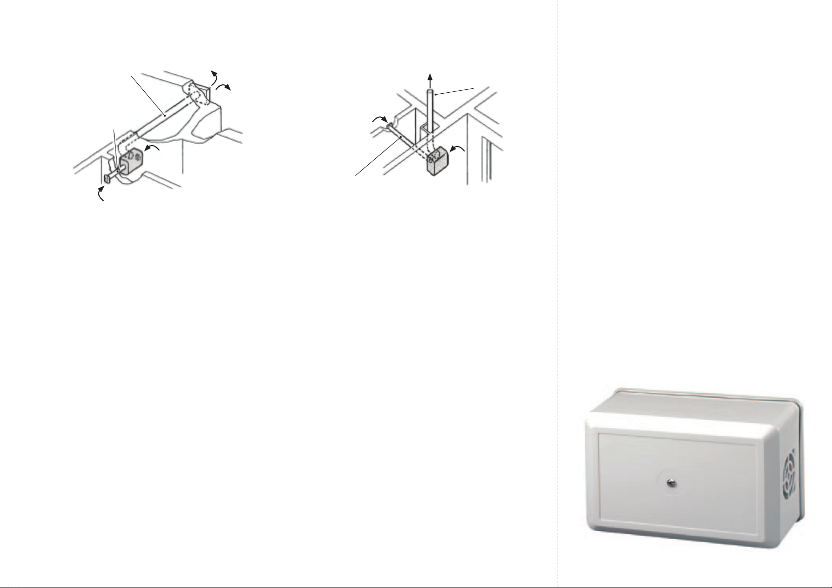
Installation
Horizontal Duct Mounting
For speed and ease of installation use Greenwood
Flexiduct.
1. Cut an opening 100mm diameter through the wall with
slight fall to exterior.
2. Remove fan cover.
3. Drill and plug 4 screw holes suitable for No.8 screws.
4. Fit adhesive foam plastic strip around exhaust spigot (not
required if exiduct hose-clip is used).
5. Fit adhesive foam plastic strip around secondary inlet
spigot if required.
6. Fit rubber sealing strip around base plate of unit.
Ensuring that is has shortest side outward. (P1 only).
7. Fit anti-back-draught shutter into exhaust spigot ensuring
hinge is to the top. (P1 only).
8. Fit base plate to wall using No.8 screws.
Note: PD only to t, motor chassis may be unscrewed
and unplugged from the base plate before xing base
plate to the wall.
9. Fit timer if required.
(See separate installation instructions).
10. Wire fan as required. (See wiring diagram).
11. If cable knock outs in Terminal Block Cover are removed,
ensure that the edges of the knock outs are dressed so
that the external cable insulation is not damaged by any
sharp edges.
12. Replace cover, ensuring printed circuit tongue locates in
the electrical connector and is fully home.
Installation
Vertical Duct Mounting
For speed and ease of installation use Greenwood
Flexiduct.
1. Cut an opening 100mm diameter through the wall with a
set in duct.
2. Remove fan cover.
3. Drill and plug 4 screw xing holes.
4. Fit adhesive foam plastic strip around exhaust spigot (not
required if exiduct hose-clip is used).
5. Fit adhesive foam plastic strip around secondary inlet
spigot if required.
6. Fit rubber sealing strip around base plate of unit. Ensuring
that is has shortest side outward. (P1 only).
7. Fit anti-back-draught shutter into exhaust spigot ensuring
hinge is to the top. (P1 only).
8. Fit base plate to wall using No.8 screws.
Note: PD only to t, motor chassis may be unscrewed and
unplugged from the base plate before xing base plate to
the wall.
9. Fit timer if required.
(See separate installation instructions).
10. Wire fan as required. (See wiring diagram).
11. If cable knock outs in Terminal Block Cover are removed,
ensure that the edges of the knock outs are dressed so
that the external cable insulation is not damaged by any
sharp edges.
12. Replace cover, ensuring printed circuit tongue locates in
the electrical connector and is fully home.
Wiring Notes
1. All wiring must be in accordance with prevailing
national standards (eg. BS7671 IEE UK Wiring
Regulations) and carried out by a qualied
electrician.
2. Switch off mains supply before commencing any
installation, electrical, cleaning, or servicing work.
3. A double pole isolating switch with a minimum
contact gap of 3mm should be used in series with
each fan.
4. For single units use a 3 amp fuse. When supplied
from a 6 amp lighting circuit no local fuse is required.
5. To wire the unit:
a. Remove the fan cover.
b. Remove screws securing connector block.
c. Remove earth test wire and discard.
d. Make all connections on rear of connector block
Note: No mains connections are to be made to the
front of the electrical connector at this will by-pass
the electrical isolator.
e. Replace screws securing connector block.
f. Replace cover, ensuring printed circuit tongue
engages in the electrical connector and is
fully home.
100mm Primary Duct
60mm Secondary Duct
100mm Primary Duct
60mm Secondary Duct


