The specific operation of your fan may vary depending on the way it has
been installed.
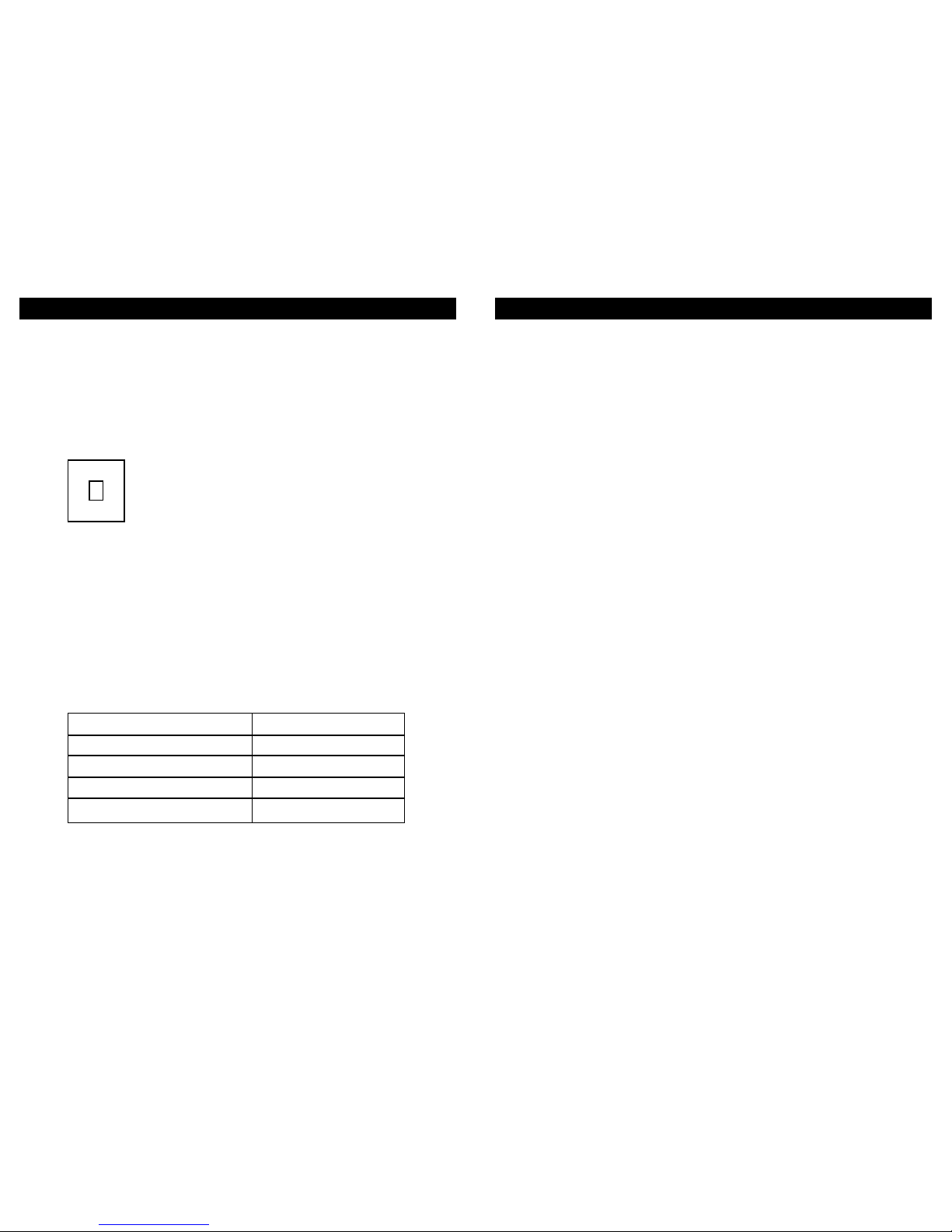
The options are –
Trickle Speed: Operating on a continual basis.
Boost Speed: Activated manually using our GS2 switch or via the
room light switch.
GS2 switch markings - Trickle (I) & Boost (II)
Operation
Note: Other manufacturers switches may show different markings.
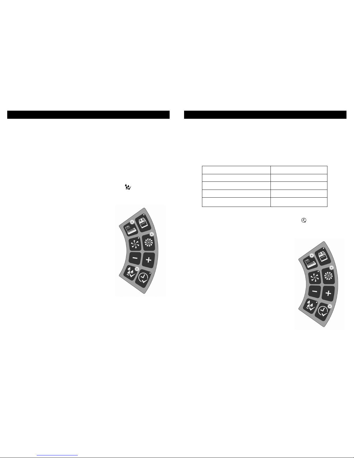
To maintain a healthy indoor environment the Unity CV2GIP / CV2SVGIP
includes SMART technology for Over-run Timer (Greenwood
TimerSMARTTM) and Humidity (Greenwood HumidiSMARTTM).
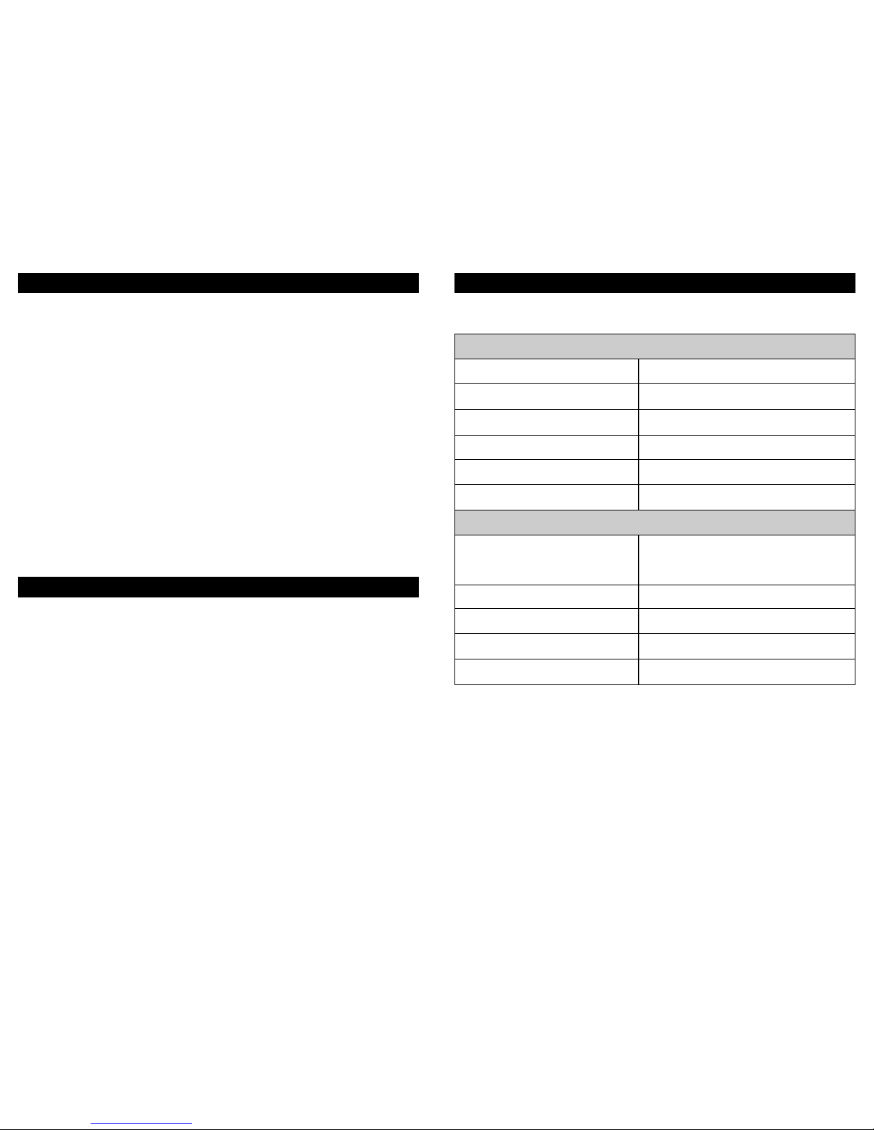
Greenwood TimerSMARTTM monitors the length of time that there is an
occupancy presence within a wet room (via the ‘switch-live’) and provides
a fixed over-run time period to best match the length of time that the
‘switch live’ is active (as shown below):
Note: The first 5 minutes will not activate an over-run.
This removes nuisance running noise and unnecessary energy wastage
typically associated with traditional timers.
4 5
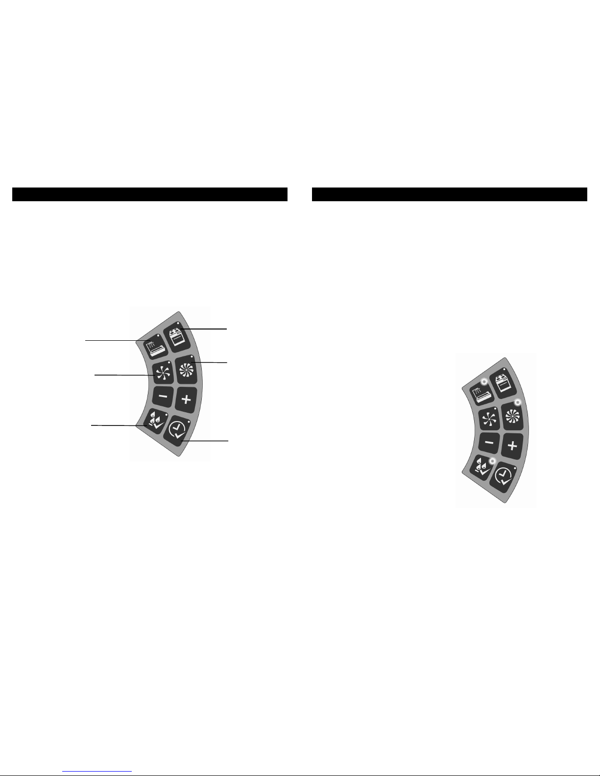
2.0 General Overview
2.1.1
2.1.2
2.1.3
Greenwood HumidiSMARTTMmonitors the ambient humidity within the
wet room environment and looks for short peaks of humidity made by
either showering or bathing. This smart technology ensures that your
Unity CV2GIP / CV2SVGIP is not on boost for prolonged periods of time
removing nuisance running noise and unnecessary energy wastage
typically associated with increases to background humidity which
naturally occurs with the changing seasons.
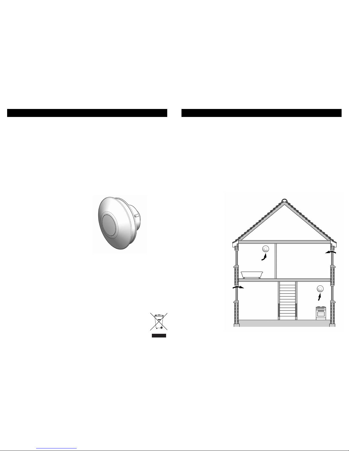
To maintain good indoor air quality within the dwelling it is important
that the fan remains in operation at all times unless switched off for
maintenance. (See section 4.0 Servicing / Maintenance).
Depending on when your home was built background window trickle
ventilators may be provided in dry habitable rooms. Trickle vents should
not be installed in the same rooms as the fan, as overall ventilation
effectiveness can be reduced.
Warning: This appliance can be used by children aged from 8
years and above and persons with reduced physical sensory or
mental capabilities or lack of experience and knowledge if they
have been given supervision or instruction concerning use of the
appliance in a safe way and understand the hazards involved.
Children shall not play with the appliance.
Where an open-flued oil or gas-fuelled appliance is installed
precaution must be taken to avoid a back-flow of gases into
the room.
The CV2SVGIP fan must only be installed by using the supplied
Safety Extra Low Voltage (SELV) controller corresponding to the
markings on the appliance.
Cleaning and user maintenance shall not be made by children
without supervision.
Always isolate fan from mains supply before cleaning. Do not use
solvents to clean this fan.
2.1.4
2.1.5
2.1.6
2.1.7
2.1.8
2.1.9
2.1.10
2.1.11
II
I
Time ‘Switch Live’ is Active
0– 5 minutes
5–10 minutes
10 – 15 minutes
15+ minutes
Over-run Boost Period
No over-run
5 minutes
10 minutes
15 minutes