GREINER Scheel-mann Technical document

made by

2 / 16
- Mounting and operating manual
© 2018 GREINER GmbH
081_instruction-manual_EN0815502_rev_0.docx
Mounting and operating manual
Item No.: 0815502
Last updated: 17.05.2018 / Rev.: 0
Copyright: © 2018 GREINER GmbH
All copyrights to this mounting and operating manual remain with GREINER GmbH. Reprinting - even in extracts -
is not permitted. The transfer of this manual to third parties requires the written permission of GREINER GmbH.
Any use or modification outside the narrow limits of copyright law is not permitted without the consent of
GREINER GmbH. This applies in particular to duplication, translation, microfilming and storage as well as processing
in electronic systems.

Table of contents
© 2018 GREINER GmbH
- Mounting and operating manual
3 / 16
081_instruction-manual_EN0815502_rev_0.docx
Table of contents
1General 4
1.1 Scope of delivery 4
2Mounting 5
2.1 Mounting the guide rails (option) 5
2.2 Mounting the armrests (option) 7
2.3 Installing the seat in the vehicle 8
2.3.1 Electrical connection (option) 8
3Structure 9
4Operation 10
4.1 Seat length adjustment (option) 10
4.2 Backrest inclination adjustment 10
4.3 Headrest adjustment 11
4.4 Folding the backrest (option) 12
4.5 Seat depth adjustment 12
4.6 4-way lumbar support (option) 13
4.7 Side bolster adjustment in backrest 13
4.8 Heating in seat and back (option) 14
4.9 E-package for Vario and Vario XXL 14
4.10 Armrest adjustment (option) 15
4.11 LR Edition 15

1 General
4 / 16
- Mounting and operating manual
© 2018 GREINER GmbH
081_instruction-manual_EN0815502_rev_0.docx
1General
This mounting and operating manual (hereinafter also referred to as the "manual") also describe functions or fea-
tures that may not be included in your retrofit seat (hereinafter also referred to as the "seat").
We reserve the right to make technical changes without notice within the scope of further development of the
seat described in this manual.
The original of this manual was written in German. All other languages are translations of this manual.
Validity
This manual applies only to the seat and accessories supplied by GREINER GmbH (also abbreviated to GREINER).
Manufacturer
GREINER GmbH
Wettestraße 1
74385 Pleidelsheim / Germany
Phone: +49-7144-8112-0
Fax: +49-7144-8112-99
www.greiner-gmbh.de
Note on pictorial representations
The photos / illustrations are general illustrations and may differ from the actual conditions or from the compo-
nents actually used.
Warranty and liability
Our General Terms and Conditions (GTC) apply in the currently valid version at www.greiner-gmbh.de.
In the event of a complaint (damage, defects or other reasons for complaint), your specialist distributor is the
appropriate contact person.
Disposal
During the construction of the seat, care was taken to ensure that, wherever possible, no composites were used.
This design concept allows a high degree of recycling once the seat has reached the end of its service life.
In the event of scrapping, dispose of metal and plastic parts separately and properly.
If you have any queries, please contact your local municipality, local waste disposal company or our service.
Country-specific disposal regulations must be observed!
1.1 Scope of delivery
Standard
Individually packed seats (reclining position)
Headrest removed and enclosed
Set of screws for fastening
6x cylindrical screw with flat head
(DIN 7984 M8 x 25 mm galv. strength class 8.8 polyamide coated)
6x internal toothed washer
(DIN 6797 I M8 galv.)
This mounting and operating manual
Option
Guide rail set (left and right running rail with release lever)
Vehicle-specific adapter or console
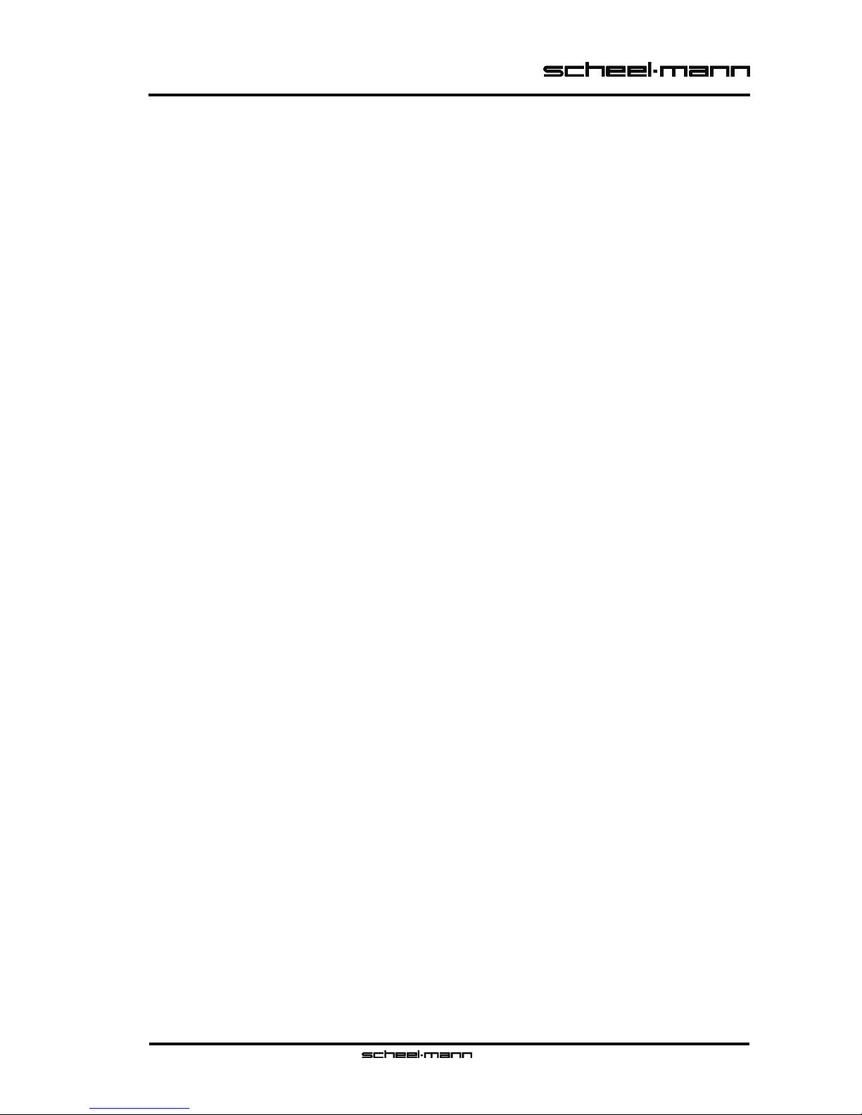
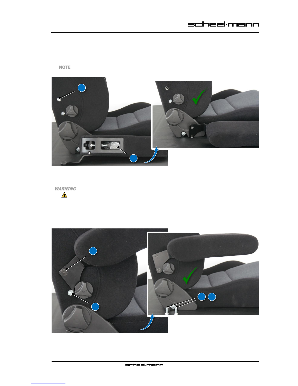
Armrest(s) with 2x fastening screws
(DIN 7991 M10 x 30 mm strength class 8.8 black polyamide coated version)

2 Mounting
© 2018 GREINER GmbH
- Mounting and operating manual
5 / 16
081_instruction-manual_EN0815502_rev_0.docx
2Mounting
1. Raise up the backrest (see 4.2 Backrest inclination adjustment) (without Fig.).
2. Insert headrest correctly (see 4.3 Headrest adjustment) (without Fig.).
2.1 Mounting the guide rails (option)
The mounting of the optional guide rail set of the company GREINER GmbH is described here.
1. Move the two guide rails to the mounting position as shown.
If necessary, after loosening the locking mechanism (screwdriver), move the guide rails until the
two rear mounting points (A) are accessible.
A. Rear mounting points
Fig. 1 Mounting the guide rails (option) - move the guide rails into mounting position
2. Move the seat to the mounting position (seat in reclining position - seat and backrest upholstery
downwards - use a clean underlay, if necessary).
3. Align the two guide rails (B) as shown (do not mix up right and left or top and bottom).
4. First screw in the two rear fastening screws (C) together with the toothed washers (D) (only apply
the screw head - do not tighten).
B. Guide rail
C. Fastening screw
D. Toothed washer
Fig. 2 Mounting the guide rails (option) - screw in rear fastening screws (do not tighten)
5. After loosening the locking mechanism (screwdriver), the guide rails must be moved until the front
mounting points (E) are accessible.
6. Now screw in the corresponding front fastening screw (F) together with the toothed washer (G)
and tighten to 25 Nm.
E. Front mounting points
F. Fastening screw
G. Toothed washer
Fig. 3 Mounting the guide rails (option) - screw in and tighten the front fastening screws
A
C
D
B
E
G
F

2 Mounting
6 / 16
- Mounting and operating manual
© 2018 GREINER GmbH
081_instruction-manual_EN0815502_rev_0.docx
7. Hook in the release lever (H) correctly (offset must point downwards).
H. Release lever
Fig. 4 Mounting the guide rails (option) - hook in release lever
8. Now operate the release lever and move the guide rails until the two rear mounting points are ac-
cessible.
9. Then tighten each of the two rear fastening screws to 25 Nm.
Fig. 5 Mounting the guide rails (option) - tighten the rear fastening screws
10. Carry out a final functional check of the guide rails and their locking mechanism (see 4.1 Seat
length adjustment (option)).
WARNING
The fixing of the seat is relevant to safety and must therefore be strictly observed.
The standard screw set for fastening is matched to the optional guide rail set of GREINER GmbH.
When fastening to other guide rails or directly to adapters or brackets, the minimum or maximum
screw-in depth from the surface contour of the six screw-on points on the seat must be observed.
Minimum screw-in depth 20 mm
Maximum screw-in depth 25 mm
The selection of screws with regard to head shape and strength class must be based on the stand-
ard screw set for fastening by GREINER GmbH. When using screws not coated with polyamide, it
is essential to use a suitable liquid screw locking.
Fig. 6 Mounting the guide rails (option) - screw-in depth
H

2 Mounting
© 2018 GREINER GmbH
- Mounting and operating manual
7 / 16
081_instruction-manual_EN0815502_rev_0.docx
2.2 Mounting the armrests (option)
The mounting of the optional armrests from GREINER GmbH is described here.
1. Remove the top provisional fastening screw (I) of the backrest fitting.
(galv. version - not polyamide coated).
NOTE
Do not remove both fastening screws of the backrest fitting at the same time.
This makes it unnecessarily difficult to install the armrest.
I. Provisional fastening screw (top)
J. Final fastening screws
(plastic bag)
Fig. 7 Mounting the armrests (option) - remove provisional fastening screw (top)
2. Screw the supplied final fastening screw (J) into the top of the backrest fitting
(only apply screw head - do not tighten).
WARNING
The fixing of the backrest fitting is relevant to safety and must therefore be strictly ob-
served.
The provisional fastening screws must not be used for the final mounting of the armrests.
3. When replacing the bottom provisional fastening screw (K) of the backrest fitting, follow the same
procedure as for the top one (without Fig.).
4. Now tighten the two final fastening screws to 48 Nm.
If necessary, dispose of both provisional fastening screws (I + K).
I. Provisional fastening screw (top)
J. Final fastening screw
K. Provisional fastening screw (bottom)
Fig. 8 Mounting the armrests (option) - screw in and tighten the final fastening screws
5. Carry out a final function check of the armrest(s) (see 4.10 Armrest adjustment (option)).
J
I
K
J
I
K

2 Mounting
8 / 16
- Mounting and operating manual
© 2018 GREINER GmbH
081_instruction-manual_EN0815502_rev_0.docx
2.3 Installing the seat in the vehicle
The installation of the retrofit seat in the vehicle is described here. Globally it can be said that the fixing screws
(usually 4) have to be removed and the retrofit seat has to be fixed to the vehicle structure by means of adapters
or brackets.
NOTE
Due to the variety of vehicles, the enclosed instructions must always be observed, depending on
the version of the adapter or bracket used.
2.3.1 Electrical connection (option)
NOTE
The battery must be disconnected before working on the electrical system of the vehicle.
The security code for recommissioning the radio, navigation system etc. should therefore be avail-
able.
The switch can be positioned as required
(cable length).
When installing, observe the required di-
ameter of 20 mm and the position of the
recess for locking the switch.
Fig. 9 Electrical connection (option) - installation of the switch for heating in the seat and back (cable harness)
The electrical connection is protected by
fuses.
Fig. 10 Electrical connection (option) - circuit diagram for heating in seat and back (cable harness)

3 Structure
© 2018 GREINER GmbH
- Mounting and operating manual
9 / 16
081_instruction-manual_EN0815502_rev_0.docx
3Structure
The structure of a retrofit seat is shown here using the example of a Vario F (0841124) without and with e-package.
Fig. 11 Structure of the seat
1. Seat length adjustment (option)
2. Seat depth adjustment
3. 4-way lumbar support curvature adjustment
4. Headrest
5. Release folding backrest - both sides (option)
6. Side bolster adjustment in backrest
7. Baggage net (option)
8. 4-way lumbar support height adjustment
9. Backrest inclination adjustment - both sides
10. Operating panel - e-package (left or right)
7
4
1
2
5
6
7
9
10
3
8

4 Operation
10 / 16
- Mounting and operating manual
© 2018 GREINER GmbH
081_instruction-manual_EN0815502_rev_0.docx
4Operation
The operation of a retrofit seat is shown here using the example of a Vario F (0841124) without and with e-package.
4.1 Seat length adjustment (option)
By pulling the release lever (1), the complete seat can be pushed back and forth by means of guide rails.
The adjustment is latching and is limited by stops on the guide rails.
1. Release lever for length adjustment of the seat
Fig. 12 Seat length adjustment (option)
4.2 Backrest inclination adjustment
The inclination of the backrest can be continuously adjusted using one of the handwheels (9) on both sides.
The possible inclination range is limited by stops.
9. Handwheel for backrest inclination adjustment
Fig. 13 Backrest inclination adjustment
1
9

4 Operation
© 2018 GREINER GmbH
- Mounting and operating manual
11 / 16
081_instruction-manual_EN0815502_rev_0.docx
4.3 Headrest adjustment
The headrest (4) can be adjusted in height simply by pulling it out or pushing it in. The adjustment is noticeably
engaging in 4 positions (11). The headrest can be tilted continuously. The possible tilt range is limited by stops.
No tilt adjustment on Retro model.
4. Headrest
11. Scanning
Fig. 14 Headrest adjustment
Removing the headrest on Traveller, Touring, Vario, Vario XXL and Retro models
On the Traveller, Touring, Vario, Vario XXL and Retro models, the cotter pin (12) must be pressed right in the
direction of travel to remove the headrest. To do this, carefully insert your hand between back upholstery and
side bolster and feel the cotter pin. The cotter pin releases the lock when sufficiently twisted.
Removing the headrest on the Sportline model
On the Sportline model, the cotter pin must also be pressed right in the direction of travel to remove the head-
rest. To do this, feel the round release button (13) on the rear side. The cotter pin releases the lock when suffi-
ciently twisted.
12. Cotter pin
(Traveller, Touring, Vario, Vario XXL and Retro)
13. Release button
(Sportline)
Fig. 15 Removing the headrests
11
12
4
13

4 Operation
12 / 16
- Mounting and operating manual
© 2018 GREINER GmbH
081_instruction-manual_EN0815502_rev_0.docx
4.4 Folding the backrest (option)
The backrest can be folded forward after pulling one of the release levers (5) on both sides. To fold back, simply
move the backrest to the starting position.
5. Release lever for folding the backrest
Fig. 16 Folding the backrest (option)
4.5 Seat depth adjustment
The depth of the seat cushion can be continuously adjusted by means of the handwheel (2). Stops limit the pos-
sible adjustment range.
Exclusive feature on the Vario and Vario XXL models.
2. Handwheel for seat depth adjustment
Fig. 17 Seat depth adjustment
2
5

4 Operation
© 2018 GREINER GmbH
- Mounting and operating manual
13 / 16
081_instruction-manual_EN0815502_rev_0.docx
4.6 4-way lumbar support (option)
The 4-way lumbar support can be adjusted in height and curvature using the two handwheels (3 + 8). Stops limit
the possible adjustment ranges.
Not available on Sportline and Retro models.
3. Handwheel for curvature adjustment
8. Handwheel for height adjustment
Fig. 18 4-way lumbar support (option)
4.7 Side bolster adjustment in backrest
The width of the side bolsters in the backrest can be continuously adjusted by means of the handwheel (6). Stops
limit the possible adjustment range.
Exclusive feature on the Vario and Vario XXL models.
6. Handwheel for side bolster adjustment
in backrest
Fig. 19 Side bolster adjustment in backrest
8
6
3

4 Operation
14 / 16
- Mounting and operating manual
© 2018 GREINER GmbH
081_instruction-manual_EN0815502_rev_0.docx
4.8 Heating in seat and back (option)
The 2-level electric heating, installed in the seat and backrest, is supplied directly with 12 V DC via a cable har-
ness by means of relays. The position of the switch (14) and a two-colour LED signal the actual operating status.
The switch is either installed in an operating panel (10) (left or right) or on a cable harness for free installation in
a suitable position in the vehicle (see 2.3.1 Electrical connection (option)).
Version with operating panel not available for the models Sportline T/F and Retro.
10. Operating panel (left or right)
14. 2-level heating switch for seat and backrest
Low (green LED)
Off (no LED)
High (red LED)
Fig. 20 Heating in seat and back (option)
4.9 E-package for Vario and Vario XXL
The e-package enables the continuously variable electrical inclination of the backrest and the continuously electri-
cal adjustment of the 4-way lumbar support. For this purpose, three clearly marked rocker keys (16 + 17 + 18)
are installed on the operating panel (10) (left or right). The drives run as long as the keys are pressed. Stops limit
the possible adjustment ranges. The e-package is only available together with 2-level electric heating in seat and
back. The position of the switch (15) and a yellow or red LED indicate the actual operating status.
Exclusive feature on the Vario and Vario XXL models with e-package.
10. Operating panel (left or right)
15. 2-level heating switch for seat and backrest
Low (yellow LED)
Off (no LED)
High (red LED)
16. Rocker key - 4-way lumbar support
curvature adjustment
17. Rocker key - 4-way lumbar support
height adjustment
18. Rocker key - backrest inclination
Fig. 21 E-package for Vario and Vario XXL
14
10
10
15
16
18
17

4 Operation
© 2018 GREINER GmbH
- Mounting and operating manual
15 / 16
081_instruction-manual_EN0815502_rev_0.docx
4.10 Armrest adjustment (option)
The height of the folded down arm support (19) can be adjusted with the aid of a stopping screw (20). To fold
up, simply guide the arm support upwards. The stop screw and a fixed stop between arm support and armrest
holder (21) limit the possible range of movement. The movement of the arm support can be adjusted by means
of a plastic clamping screw (22).
Not available for model Retro.
19. Arm support
20. Stopping screw
21. Armrest holder
22. Clamping screw (plastic)
Fig. 22 Armrest adjustment (option)
4.11 LR Edition
The scheel-mann LR Edition models are based on the basic models, but are specially optimized for installation in
the Land Rover Defender®. The foldable seat (approx. 90°) allows quick access to the on-board electronics.
Simply pull the safety splint (23) out of the bolt (24) and fold up the seat (25). To fold the seat back, return it to
its original position and reinsert the bolt. To fasten the seat, reinsert the safety pin and re-engage it correctly.
NOTE
To install the scheel-mann retrofit seats, in vehicles 90 and 110 with hardtop, a conversion of the
bulkhead wall is necessary.
23. Safety splint
24. Bolt
25. Seat
Fig. 23 LR Edition
19
21
24
25
24
23
20
22

This manual suits for next models
2
Table of contents