GREISINGER G 1114 User manual

Operating manual
G 1114
Vacuum meter | barometer
EN

Table of contents
2 / 28 B-H88.0.14.DB2-1.0
Table of contents
1 About this documentation ................................................................................................................. 4
1.1 Foreword............................................................................................................................................... 4
1.2 Purpose of the document...................................................................................................................... 4
1.3 Legal notices......................................................................................................................................... 4
1.4 Correctness of content.......................................................................................................................... 4
1.5 Layout of this document........................................................................................................................ 4
1.6 Further information ............................................................................................................................... 5
2 Safety ................................................................................................................................................... 6
2.1 Explanation of safety symbols .............................................................................................................. 6
2.2 Safety instructions ................................................................................................................................ 6
2.3 Foreseeable misuse ............................................................................................................................. 6
2.4 Intended use ......................................................................................................................................... 6
2.5 Qualified personnel............................................................................................................................... 7
3 Description .......................................................................................................................................... 8
3.1 Scope of delivery .................................................................................................................................. 8
3.2 Functional description........................................................................................................................... 8
4 The product at a glance ..................................................................................................................... 9
4.1 The G 1114........................................................................................................................................... 9
4.2 Display elements .................................................................................................................................. 9
4.3 Operating elements .............................................................................................................................. 9
4.4 Connections........................................................................................................................................ 10
5 Operation........................................................................................................................................... 11
5.1 Commissioning ................................................................................................................................... 11
5.1.1 Explanation ......................................................................................................................................... 11
5.2 Configuration ...................................................................................................................................... 11
5.2.1 Explanation ......................................................................................................................................... 11
5.2.2 Opening the configuration menu......................................................................................................... 11
5.2.3 Configuring parameters of the configuration menu............................................................................. 12
5.2.4 Open the adjustment menu ................................................................................................................ 13
5.2.5 Parameters of the adjustment menu................................................................................................... 14
6 Measurement Basics ........................................................................................................................ 16
6.1 Vacuum measurements...................................................................................................................... 16
6.2 Special functions................................................................................................................................. 16
6.2.1 NVLL Tare function ............................................................................................................................... 16
6.2.2 AVR 0:02 / AVR 0:05 / AVR 0: 10 ............................................................................................................. 16
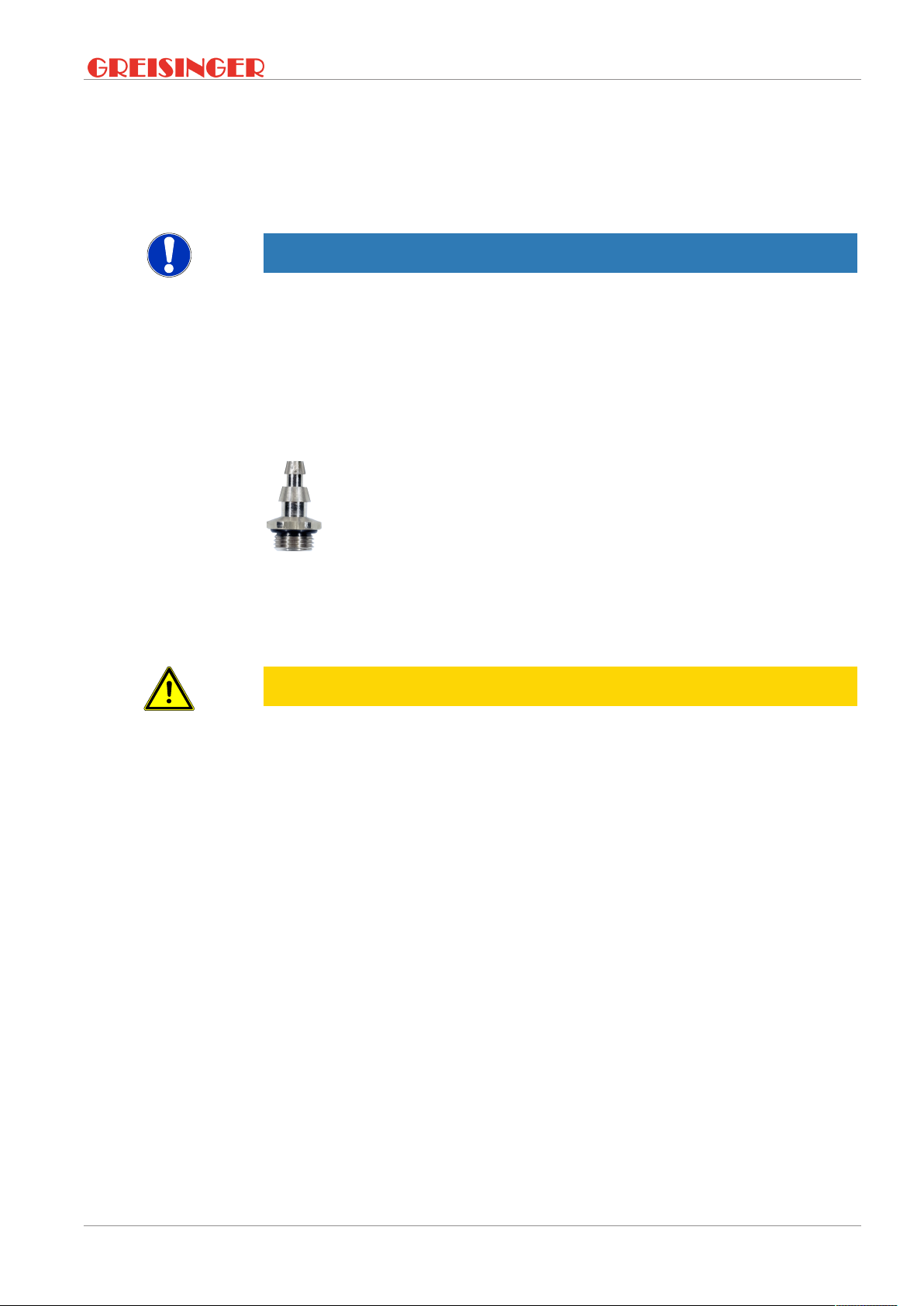
6.3 Pressure connections ......................................................................................................................... 17
6.4 UT operation ....................................................................................................................................... 17
6.5 QC6 operation .................................................................................................................................... 18
6.6 ST6 operation ..................................................................................................................................... 18
6.7 MCM operation ................................................................................................................................... 18
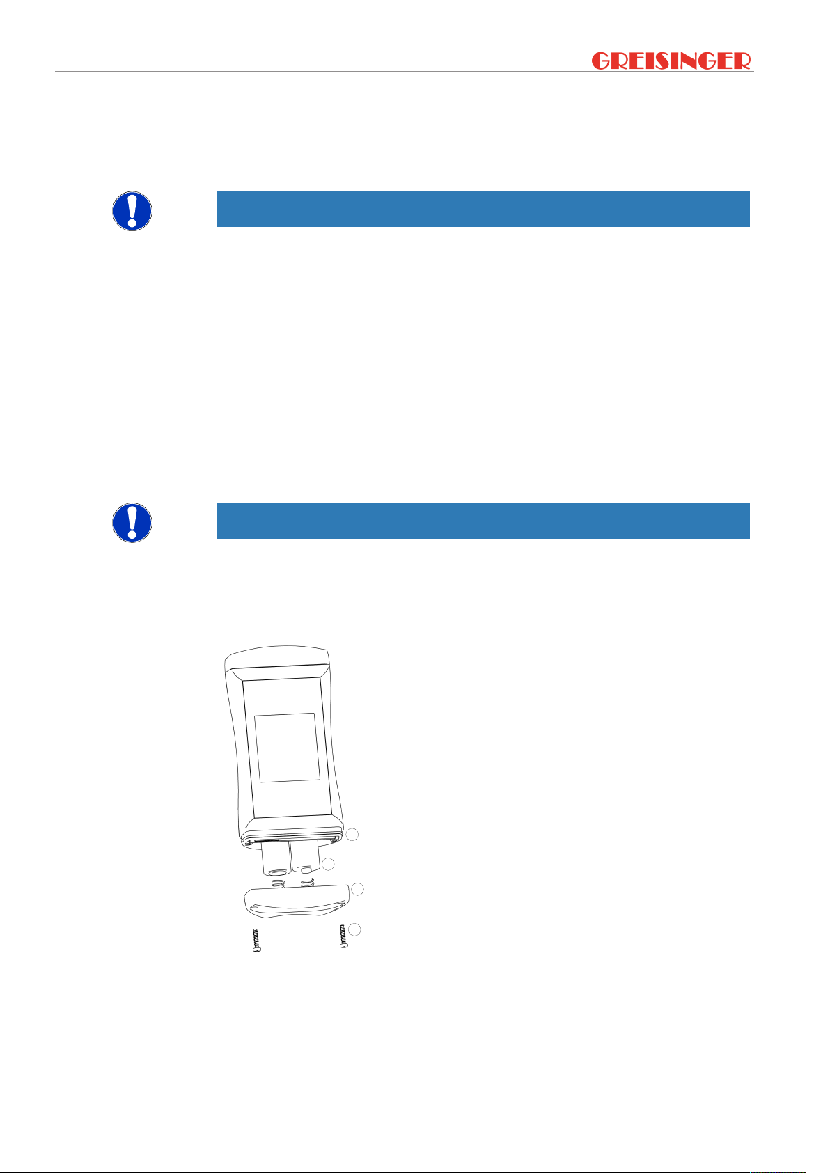
6.8 Replacement of pressure hoses ......................................................................................................... 19
6.9 Protection of sensors with use of filter membranes ............................................................................ 19
7 Operation and maintenance ............................................................................................................ 20
7.1 Operating and maintenance notices ................................................................................................... 20

Table of contents
B-H88.0.14.DB2-1.0 3 / 28
7.2 Battery ................................................................................................................................................ 20
7.2.1 Battery indicator.................................................................................................................................. 20
7.2.2 Changing battery ................................................................................................................................ 20
7.3 Calibration and adjustment service..................................................................................................... 21
7.3.1 Certificates.......................................................................................................................................... 21
8 Error and system messages............................................................................................................ 22
9 Disposal............................................................................................................................................. 23
10 Technical data................................................................................................................................... 24
11 Spare parts and accessories ........................................................................................................... 25
12 Ordering code ................................................................................................................................... 26
13 Service ............................................................................................................................................... 27
13.1 Manufacturer....................................................................................................................................... 27
13.2 Repairs processing ............................................................................................................................. 27
13.3 Sales offices ....................................................................................................................................... 27
13.4 Sales subsidiaries............................................................................................................................... 28

1 | About this documentation G 1114
4 / 28 B-H88.0.14.DB2-1.0
1 About this documentation
1.1 Foreword
Read this document carefully and familiarise yourself with the operation of the product
before you use it. Keep this document ready to hand and in the immediate vicinity of
the product so that it is available to the personnel/user for reference at all times in
case of doubt.
The product was developed according to the state of the art and fulfils the require-
ments of the applicable European and national Directives. All corresponding docu-
ments are available from the manufacturer.
_
Only technically qualified persons are permitted to carry out commissioning, operation,
maintenance and decommissioning. The qualified personnel must have carefully read
and understood the operating manual before beginning any work.
1.2 Purpose of the document
_
– This document describes the operation of the product.
– It provides important information for operating safely and efficiently with the
product.
– In addition to the quick reference guide with all relevant legal and safety content in
hard copy, this document is a detailed reference option for the product.
1.3 Legal notices
_
The liability and warranty of the manufacturer for damages and consequential dam-
ages are voided with misuse, disregarding this document, disregarding safety notices,
assignment of inadequately qualified technical personnel and arbitrary modifications of
the product.
Only carry out the maintenance and service tasks on this product that are described in
this documentation. In the process, adhere to the specified steps. For your own safety,
only use original spare parts and accessories of the manufacturer. We assume no li-
ability for the use of other products and resulting damage.
This document is entrusted to the recipient for personal use only. Any impermissible
transfer, duplication, translation into other languages or excerpts from this operating
manual are prohibited.
The manufacturer assumes no liability for print errors.
1.4 Correctness of content
The contents of this document were checked for corrected and are subject to a con-
tinuous correction and updating process. This does not rule out potential errors. In the
event that errors are discovered or in case of suggestions for improvement, please in-
form us immediately via the indicated contact information in order to help us make this
document even more user-friendly.
1.5 Layout of this document
Description
Each chapter is explained at the beginning in the description.

G 1114 About this documentation | 1
B-H88.0.14.DB2-1.0 5 / 28
Prerequisite
All mandatory prerequisites are then listed for each step.
Instruction
Tasks to be carried out by the personnel / user are represented as numbered instruc-
tions. Adhere to the sequence of the specified instructions.
Representation
Shows an illustrative instruction or a configuration of the product.
Formula
Some instructions include a formula for a general understanding of a configuration,
programming or a setting of the product.
Outcome of an action
Result, consequence or effect of an instruction.
Emphases
In order to simplify legibility and provide a clearer overview, various sections / informa-
tion are emphasised.
–1234 Display elements
–Mechanical controls
–Product functions
–Product labels
–Cross-reference [}p.4]
–Foot notes
1.6 Further information
_
Software version of the product:
– V1.1 or later

2 | Safety G 1114
6 / 28 B-H88.0.14.DB2-1.0
2 Safety
2.1 Explanation of safety symbols
_
DANGER
This symbol warns of imminent danger which can result in death, severe bodily injury,
or severe property damage in case of non-observance.
_
CAUTION
This symbol warns of potential dangers or harmful situations which can cause damage
to the device or to the environment in case of non-observance.
_
NOTE
This symbol indicates processes which can have a direct influence on operation or
can trigger an unforeseen reaction in case of non-observance.
2.2 Safety instructions
_
NOTE
This product does not belong in children's hands!
2.3 Foreseeable misuse
_
The fault-free function and operational safety of the product can only be guaranteed if
applicable safety precautions and the device-specific safety instructions for this docu-
ment are observed.
If these notices are disregarded, personal injury or death, as well as property damage
can occur.
_
DANGER
Incorrect area of application!
In order to prevent erratic behaviour of the product, personal injury and property dam-
age, the product must be used exclusively as described in the chapter Description
[}p.8] in the operating manual.
– The product is not suitable for use in explosion-prone areas!
– The product must not be used for diagnostic or other medical purposes on pa-
tients!
– For measurements requiring devices that are subject to authorisation or special
approvals, this product is not a substitute for such products and can only be used
as an aid in preparatory or comparison measurements!
2.4 Intended use
_
_
_

G 1114 Safety | 2
B-H88.0.14.DB2-1.0 7 / 28
The G 1114 measures the absolute pressure in the air, clean water or in non-corros-
ive/non-ionising gases. A direct measurement of the environmental pressure can take
place or the measurement pressure is taken with a suitable hose connected to the
port. Relative measurements can also be conducted with the integrated special func-
tion NVLL.
Applications include:
– Barometric measurements (e.g. weather)
– Vacuum measurements (up to 0 hPa abs., negative pressure via hose or even
with complete device evacuation)
– Pneumatic measurements (up to 14000 hPa abs. or 14 bar abs.)
The pressure connection is made at the supplied interchangeable pressure connection
ports with suitable hoses - 4 different connection options are available as standard,
many other connection options can be used easily and reliable with G 1/8 adapters.
The device must only be used under the conditions and for the purposes for which it
was designed.
It must be handled with care and used according to the technical data (do not throw,
strike, etc.). Suitable measures must be used to protect the pressure connections and
be protected from dirt.
_
NOTE
Complete evacuation see Vacuum measurements [}p.16].
2.5 Qualified personnel
_
For commissioning, operation and maintenance, the relevant personnel must have ad-
equate knowledge of the measuring process and the significance of the measure-
ments. This document makes a valuable contribution to this. The instructions in this
document must be understood, observed and followed.
In order to avoid any risks arising from interpretation of the measurements in the con-
crete application, the user must have additional expertise. The user is solely liable for
damages/danger resulting from misinterpretation due to inadequate expertise.

3 | Description G 1114
8 / 28 B-H88.0.14.DB2-1.0
3 Description
3.1 Scope of delivery
Please check to ensure the completeness of the product after opening the package.
You should find the following components:
– Quick reference guide
– Handheld measuring device, ready for operation, including batteries
– Test protocol
_
NOTE
Individual components may vary depending on which set you have selected.
3.2 Functional description
_
The product offers precision, speed and reliability in a compact, ergonomic housing.
Additional impressive features include the waterproof design in accordance with IP 67
and the 3-line illuminated display, which offers a 180° rotated display at the push of a
button. A high-quality, position-independent sensor is the key component. The operat-
ing elements are used to switch the product on and off and for configuration.
The following basic functions are also provided:
– Min/max value display
– Freeze measurement (hold function)
– Zero function
– Switching of the display to head-up
The pressure connection of gas hoses is selectable.
– UT connection for 6 x 1 mm hoses (4 mm inside, e.g. PVC hoses GDZ-01) and 8 x
1 mm (6 mm inside, e.g. silicon hoses for quick connection in heating service
GDZ-31)
– QC6 Quick-Connect for 6 x 1 mm (Ø 4 mm inside) PVC, PE, PUR, PA hoses
– QC6 screw connection for 6 x 1 mm (Ø 4 mm inside) PVC, PE, PUR, PA hoses
– MCM mini-quick coupling connection for quick couplers
_
NOTE
The pressure connection can be changed out at any time at the G 1/8 inch universal
port. You can choose the most practical connection type for your application - the ba-
sic device remains the same.

G 1114 The product at a glance | 4
B-H88.0.14.DB2-1.0 9 / 28
4 The product at a glance
4.1 The G 1114
LCD Display
Connection variants
Top view
4.2 Display elements
_
Display
_
Battery indicator Evaluation of the battery status
_
Unit display Display of the units or Min/Max/Hold information
text
_
Main display Measurement of the current pressure or value for
min/max/hold
_
Auxiliary display Measurement of the current pressure in Min/Max/
Hold mode
_
4.3 Operating elements
_
On / Off button
Press briefly Switch on the product
Activate / deactivate lighting
Long press Switch off the product
Reject changes in a menu
_
Up / Down button
Press briefly Display of the min/max value
Change value of the selected parameter
Long press Reset the min/max value of the current measure-
ment
Both simultaneously Rotate display, overhead display
_

4 | The product at a glance G 1114
10 / 28 B-H88.0.14.DB2-1.0
Function key
Press briefly Freeze measurement (Hold)
Return to measurement display
Call up next parameter
Long press, 2s Start menu configuration, (ONF appears in the dis-
play
Close menu, changes are saved
Long press, 4s Depending on the selected special function: Activa-
tion of the Tare function NVLL or rapid measurement
with mean value AVR
4.4 Connections
Universal connection Interchangeable pressure connection via G1/8"
thread.

G 1114 Operation | 5
B-H88.0.14.DB2-1.0 11 / 28
5 Operation
5.1 Commissioning
5.1.1 Explanation
_
Description The product is switched on with the On/Off button. It may be necessary to configure
the product after switching on. See Configuration [}p.11].
_
Prerequisite – Sufficiently full batteries are inserted in the product.
_
Instruction – Press the On/Off button.
_
Outcome of an action POFF Automatic shut-
off
Automatic shut-off activated. The product is
switched off if no buttons have been pressed after
the adjusted time
PR.OF Offset correction Calibration of the pressure sensor by the customer
PR..SL Gradient correc-
tion
Calibration of the pressure sensor by the customer
SEA.LNautical norm
correction
Nautical norm correction active. Display air pres-
sure compensated to sea level
– The product is now ready for measurement.
5.2 Configuration
5.2.1 Explanation
The following steps describe how to adapt the product for your purposes.
_
NOTE
There are various configuration parameters available depending on the product ver-
sion and configuration. These can vary depending on the product version and config-
uration.
5.2.2 Opening the configuration menu
_
Description In order to configure the product, you must first open the Configuration menu. The
menu is opened as shown in the illustration.
_
Prerequisite – The product is switched on.
_
Instruction 1. Press the Function key for 2 seconds to open the Configuration menu.
2. (ONF appears in the display. Release the Function key.
3. By briefly pressing the Function key, you can scroll through the parameters. Select
the parameter you would like to configure.
4. When you have selected the desired parameter, change the parameter to the de-
sired value with the Up button or the Down button.
5. The changes are saved after running through the entire Configuration menu. STOR
appears in the display. The Configuration menu can be exited from any arbitrary
parameter by pressing and holding the Function key for 2 seconds. The changes
made up that point are saved.
_

5 | Operation G 1114
12 / 28 B-H88.0.14.DB2-1.0
Representation Call up menu Next parameter Change value Save changes Discard
changes
2s Press: Single
step
Hold: Fast
change
2s 2s
Product is
switched off
_
Outcome of an action The Configuration menu is closed after the last parameter.
NOTE
If the product is switched off without saving the configuration, the last save value is re-
produced on the next start-up of the product.
5.2.3 Configuring parameters of the configuration menu
_
Description
_
Prerequisite – The Configuration menu is open. See Opening the configuration menu [}p.11].
_
Instruction 1. Select the desired parameter you would like to configure.
2. Adjust the desired configuration in the selected parameter with the Up button or
Down button.
3. The available configuration options are listed for each parameter in the following
representation.
_
_
Representation
Parameter Values Meaning
_
Anzeigeeinheit
UN,T
HPa
mBaR
BaR
PSI
mmKG
_
Activatable special functions
FVNC
NVLL Tare function available
AVR 0:02 / AVR
0:05 / AVR 0: 10
Rapid measurement with mean value over 2 s / 5
s / 10 s activatable
_
Measuring rate
RATE Selection of the measurement speed
SLO Slow
FAST Fast
_

G 1114 Operation | 5
B-H88.0.14.DB2-1.0 13 / 28
Nautical norm correction
SEA.L
NO Inactive, display measured air pressure directly
YES Active, display air pressure compensated to sea
level
ALT, -500 .. 9000 Height above sea level in m for correction
_
Shut-off time
POFF
OFF No automatic shut-off
0:15 0:30 1:00 4:00
12:00
Automatic shut-off after a selected time in hours
and minutes, during which no buttons have been
pressed
_
Backlight
L,TE
OFF Backlight deactivated
0:15 0:30 1:00 4:00 Automatic shut-off of the backlight after a selected
time in minutes and seconds, during which no but-
tons have been pressed
ON No automatic shut off of the backlight
_
Factory settings
IN,T
NO Use current configuration
YES Reset product to factory settings. IN,T DONE appears
in the display
_
Outcome of an action
_
The changed value is saved and the Configuration menu is closed. STOR appears in
the display. If necessary, the product is restarted automatically in order to adopt the
changed values.
5.2.4 Open the adjustment menu
_
Description In order to change sensor calibration, you must first open the adjustment menu menu.
The menu is opened as shown in the illustration.
_
Prerequisite – The product is switched off.
_
Instruction 1. Press and hold the Down button.
2. Press the On/Off button to switch on the product.
3. Release the On/Off button after 1 second and then the Down button in order to call
up the adjustment menu. The display shows the first parameter.
4. By briefly pressing the Function key, you can scroll through the parameters. Select
the parameter you would like to configure.
5. When you have selected the desired parameter, change the parameter to the de-
sired value with the Up button or the Down button.
6. The changes are saved after running through the entire adjustment menu. STOR
appears in the display. The adjustment menu can be exited from any arbitrary
parameter by pressing and holding the Function key for 2 seconds. The changes
made up that point are saved.
_

5 | Operation G 1114
14 / 28 B-H88.0.14.DB2-1.0
Representation Call up menu
Hold 1s Release Release
_
Outcome of an action The adjustment menu is closed after the last parameter.
5.2.5 Parameters of the adjustment menu
_
Description Zero point
_
– For an optimal zero point calibration, a vacuum pump and a precise reference
device are needed.
– The zero point correction is used together with the gradient correction primarily for
compensation of sensor deviations. The entry takes place in the display unit.
Gradient
– A pressure reference is necessary for the gradient adjustment, e.g. in the form of a
pressure source and a reference display device.
– The gradient correction is used together with the zero point correction primarily for
compensation of sensor deviations.
_
Prerequisite – The adjustment menu has been opened. See Open the adjustment menu
[}p.13].
_
Instruction 1. Select the desired parameter you would like to configure.
2. Adjust the desired configuration in the selected parameter with the Up button or
Down button.
3. The available configuration options are listed for each parameter in the following
representation.
_
Representation Parameter Values Meaning
_
Zero point correction
PR.OF 0 No offset
PR.OF -500 .. 500 Offset active
_
Gradient compensation specification
PR.SL 0 No slope
PR.SL -5.00 .. 5.00 Slope active
_
Formula Sensor zero point correction offset PR.OF
A zero point shift can be made for the measurement.
Displayed value = measured value – offset
Standard setting: 0.0, i.e. no correction is made.
Sensor gradient correction PR.SL
The gradient of the measurement can be influenced with this factor (factor is in %):
Displayed value = measured value * (1+Pr.SL/100)
Standard setting: 0.000, i.e. no correction is made.
_
Outcome of an action The changed value is saved and the adjustment menu is closed. STOR appears in the
display.

G 1114 Operation | 5
B-H88.0.14.DB2-1.0 15 / 28
NOTE
If the product is switched off without saving the configuration, the last saved values
are reproduced on the next start-up of the product.

6 | Measurement Basics G 1114
16 / 28 B-H88.0.14.DB2-1.0
6 Measurement Basics
6.1 Vacuum measurements
The device is especially suitable to measure rough vacuum via the pressure port very
fast. But if the complete device is evacuated the following has to be considered:
CAUTION
Damage possible by fast complete evacuation!
Due to the water tight construction a complete evacuation of the device may degrade
water protection. The keypad/display screen may break loose. If the device should still
be used for this application, the following options are available:
– Remove the o-ring of the battery compartment! The Instrument then is no more
water protected! Changing battery [}p.20].
– Specialized variants G 1111-VAC!
6.2 Special functions
_
With the special functions that can be selected via the Configuration menu, the device
can be optimised for special measuring tasks. After it is switched on, the device starts
up in standard measuring mode, the relevant special function is started by pressing
and holding the Function key for 4 s.
6.2.1 NVLL Tare function
_
Prerequisite The special function FVNC NVLL has been selected in the configuration menu.
The display can be zeroed by pressing the Function key for 4 s. If the tare function is
activated, NVLL blinks in the lower display. The tare function can be reset by pressing
the Function key again for 4 s.
NOTE
The tare function is independent of the zero point correction accessible via the set-
tings menu.
6.2.2 AVR 0:02 / AVR 0:05 / AVR 0: 10
Fast measurement with mean value over 2 s / 5 s / 10 s
Mean value mode for measurement of heavily fluctuating pressures.
_
Prerequisite In the Configuration mode, a special function AVR 0:02, AVR 0:05 or AVR 0: 10 has been
selected.
By pressing and holding the Function key for 4 s. the measurement with mean value
can be activated.
The different mean value times of 2, 5 or 10 seconds can be selected depending on
the requirement.
_
The first parameter is shown in the auxiliary display.
_
_

G 1114 Measurement Basics | 6
B-H88.0.14.DB2-1.0 17 / 28
Special case If the Tare function is activated when called up, this special function AVR can be reset
by pressing and holding the Function key for 4 s. In order to reactivate the Tare, the
special function must be switched in the configuration menu.
6.3 Pressure connections
_
NOTE
Suitable hoses must be used for vacuum measurements, silicon is suitable as a hose
material due to the low rigidity.
6.4 UT operation
Universal hose connection for 6 x 1 mm (4 mm inside) and 8 x 1 mm (6 mm inside)
hoses.
Fig.4:
UT connection
The universal hose connection is suitable for plastic and silicon hoses with an outer
diameter of 6 mm, for which purpose the hoses are simply connected to the upper
part. Rubber/silicon hoses with a larger diameter (e.g. 8 mm) can also be connected.
They are fit on the lower part for this purpose.
_
CAUTION
Air pressure!
With higher pressures greater than 1 bar, the hoses must be secured to prevent unin-
tended loosening. Suitable GDZ hose clamps are used for this purpose.
– 6x1 mm PVC GDZ-01. Up to 5 bar rel., vacuum-suitable!
– 6x1 mm PE GDZ-02. Up to 10 bar rel., vacuum-suitable!
– 6x1 mm PUR GDZ-03. Up to 9 bar rel., vacuum-suitable!

6 | Measurement Basics G 1114
18 / 28 B-H88.0.14.DB2-1.0
6.5 QC6 operation
Quick-Connect for Ø 6 mm hoses.
Fig.5:
QC6 Quick-Connect
The practical quick-change connection is only suitable for plastic hoses with 6 mm
outer diameter. The hose end must be clean and undamaged for connection. It is fit by
simply pushing it in until the mechanical stop is reached. It is disconnected by simul-
taneously pressing the ring on the upper end of the connection and pulling the hose.
6.6 ST6 operation
Screw connection for 6 x 1 mm (Ø 4 mm inside) plastic hoses.
Fig.6:
ST6 screw connection
The secure screw connection is only suitable for plastic hoses with 6 mm outer dia-
meter (Ø 4 mm inside). The hose end must be clean and undamaged for connection.
The union nut must be loosened before connection. Then the hose is pushed onto the
hose nipple up to the mechanical stop. The union nut is hand-tightened to secure the
connection. Disconnection takes place by loosening the union nut and pulling on the
hose.
6.7 MCM operation
Mini-quick-coupler plug connector.

G 1114 Measurement Basics | 6
B-H88.0.14.DB2-1.0 19 / 28
Fig.7:
MCM mini-quick-coupler plug connector
Compatible quick-couplers with nominal width 2.7 mm can be used:
Fig.8:
quick-coupler
6.8 Replacement of pressure hoses
The pressure connections are screwed into the product with a standard G 1/8 inch
thread with end seal. All common pressure connections with this design can be con-
nected.
NOTE
Use a suitable tool for tightening and observe the maximum torque of 2 Nm!
6.9 Protection of sensors with use of filter
membranes
The product and the sensor can be protected easy and effectively with the use of filter
membranes (e.g. adhesive membrane for UT connections, GDZ-35). This can prevent
destruction of the product, for example, from penetration of potting compound in va-
cuum-casting applications: In the worst case scenario, only the connection has to be
replaced.

7 | Operation and maintenance G 1114
20 / 28 B-H88.0.14.DB2-1.0
7 Operation and maintenance
7.1 Operating and maintenance notices
_
NOTE
Pressure connections must be protected from soiling.
7.2 Battery
7.2.1 Battery indicator
_
If the empty frame in the battery display blinks, the batteries are depleted and must be
replaced. However, the device will still operate for a certain length of time.
_
If the BAT display text appears in the main display, the battery voltage is no longer ad-
equate for operation of the product. The battery is fully depleted.
7.2.2 Changing battery
_
_
_
NOTE
Unnecessary screwing places the water-tightness of the product, among other things,
at risk and should be avoided.
_
_
_
Description Proceed as follows to replace the batteries.
_
Prerequisites – The product is switched off.
_
Instruction
A
B
C
D
Fig.9:
Batteriewechsel
1. Unscrews the Phillips screws (A)and
remove the cover.
2. Carefully replace the two Mignon AA
batteries (B). Ensure that the polarity
is correct! It must be possible to insert
the batteries in the correct position
without using force.
3. The O-ring (C) must be undamaged,
clean and positioned at the intended
depth. In order to facilitate assembly
and avoid damage, a suitable grease
can be applied.
4. Fit the cover on evenly. The O-ring
must remain at the intended depth!
5. Tighten the Phillips screws (A).
_
Outcome of an action The product is now ready for use again.
Table of contents
Other GREISINGER Weather Station manuals