GREISINGER GTD 1100 User manual
H55.0.01.6C-07
GHM Messtechnik GmbH • Standort Greisinger
Hans-Sachs-Str. 26 • D-93128 Regenstauf
+49 (0) 9402 / 9383-0 +49 (0) 9402 / 9383-33 [email protected]
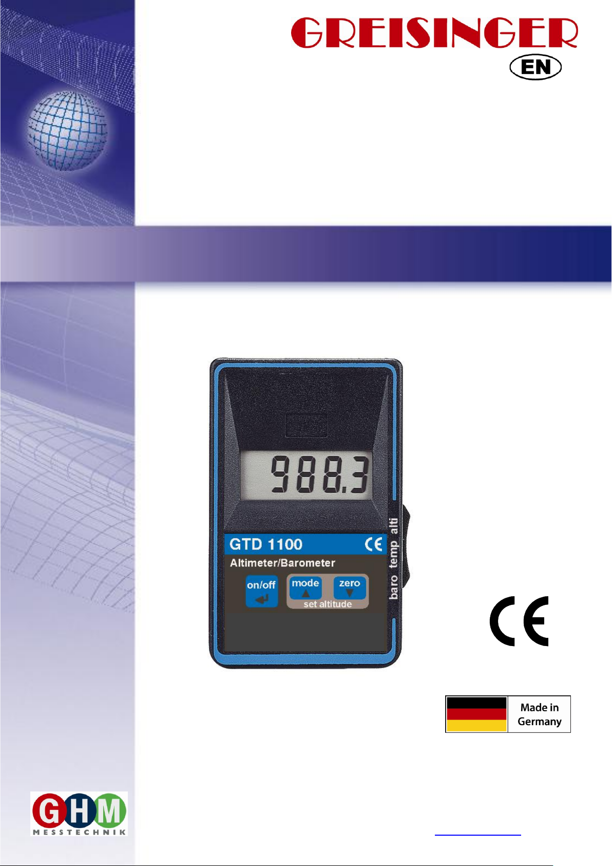
Operating Manual Precision Altimeter/Barometer
from Version 2.0 GTD 1100
WEEE-Reg.-Nr. DE 93889386

H55.0.01.6C-07 Operating Manual GTD 1100 page 2 of 8
_____________________________________________________ _____________________________________________________________________________
Content
1INTENDED USE..........................................................................................................................................2
2GENERAL ADVICE...................................................................................................................................2
3DISPOSAL NOTES.....................................................................................................................................2
4SAFETY INSTRUCTIONS........................................................................................................................3
5OPERATION AND MAINTENANCE......................................................................................................3
6OPERATION...............................................................................................................................................3
6.1 DISPLAY ELEMENTS .................................................................................................................................3
6.2 PUSHBUTTONS..........................................................................................................................................3
7STARTING...................................................................................................................................................3
8MIN-/MAX- VALUE MEMORY...............................................................................................................4
9ZERO-FUNCTION (RELATIVE MEASURING)...................................................................................4
10 MEASURINGS AND FUNCTIONS.......................................................................................................4
10.1 MEASURING ATMOSPHERIC PRESSURE (SLIDE SWITCH AT “BARO“).......................................................4
10.2 MEASURING ALTITUDE /ELEVATION (SLIDE SWITCH AT “ALTI“)...........................................................5
11 CONFIGURATION OF THE DEVICE.................................................................................................5
12 ADJUSTING OF THE INSTRUMENT.................................................................................................7
13 NOTES TO THE CALIBRATION SERVICES....................................................................................7
14 ERROR AND SYSTEM MESSAGES....................................................................................................7
15 SPECIFICATION ....................................................................................................................................8
1 Intended use
The device measures the absolute pressure of air. The current altitude can also be calculated
Field of application
Barometric measurements (weather)
Elevation determination
etc...
The safety instruction (see safety instructions) have to be observed.
The device must not be used for purposes and under conditions for that the device had not been
designed.
The device must carefully dealt with and has to be used according to the specifications (do not
throw, knock, etc.). It has to be protected against dirt.
2 General advice
Read through this document attentively and make yourself familiar to the operation of the device
before you use it. Keep this document in a ready-to-hand way in order to be able to look up in the
case of doubt.
3 Disposal notes
Dispense exhausted batteries at destined gathering places.
This device must not be disposed as “residual waste”.
To dispose this device, please send it directly to us (adequately stamped).
We will dispose it appropriately and environmentally friendly.
H55.0.01.6C-07 Operating Manual GTD 1100 page 3 of 8
_____________________________________________________ _____________________________________________________________________________
4 Safety instructions
This device has been designed and tested in accordance to the safety regulations for electronic devices.
However, its trouble-free operation and reliability cannot be guaranteed unless the standard safety measures
and special safety advises given in this manual will be adhered to when using it.
1. Trouble-free operation and reliability of the device can only be guaranteed if it is not subjected to any
other climatic conditions than those stated under “Specification”.
Transporting the device from a cold to a warm environment condensation may result in a failure of the
function. In such a case make sure the device temperature has adjusted to the ambient temperature
before trying a new start-up.
2. Whenever there may be a risk whatsoever involved in running it, the device has to be switched off
immediately and to be marked accordingly to avoid re-starting. Operator safety may be a risk if:
- there is visible damage to the device or the device is not working as specified
- the device has been stored under unsuitable conditions for a longer time
In case of doubt, please return device to manufacturer for repair or maintenance.
3. Warning: Do not use this product as safety or emergency stop device, or in any other application where
failure of the product could result in personal injury or material damage.
Failure to comply with these instructions could result in death or serious injury and material damage.
5 Operation and maintenance
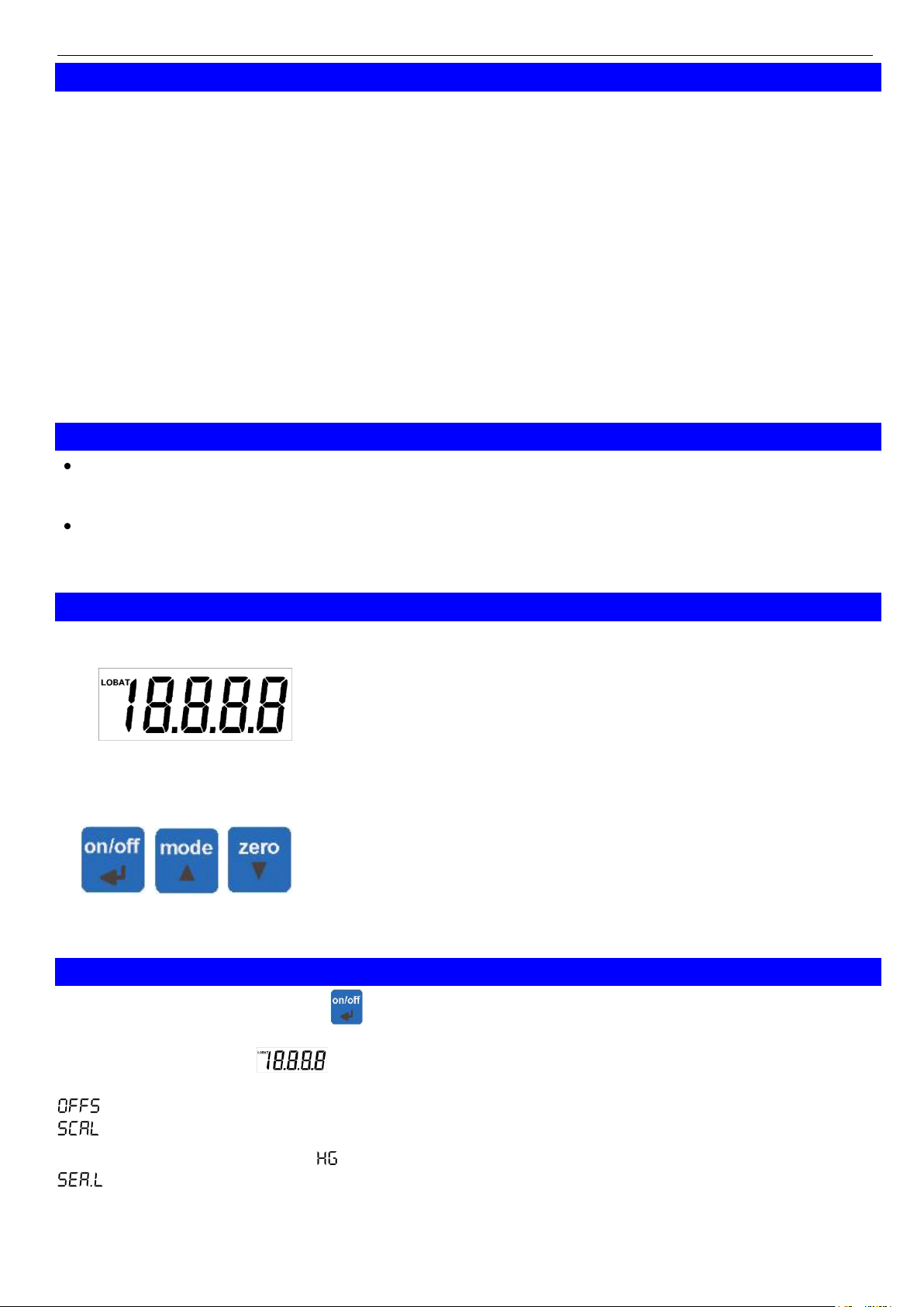
If the symbol “LOBAT”is displayed at the left side of display, the battery is weak, measuring can be
continued for a short period. If “bAt” is displayed in the main display the battery is used up and needs to
be replaced. Measuring is no more possible.
The battery has to be removed, when storing device above 50 °C.
Hint: We recommend removing the battery if device is not used for a longer period of time! Risk
of leakage
6 Operation
6.1 Display elements
1: Main display
Display of current measuring value or of
minimal measured value (“Lo” blinking) or
maximal value (“Hi” blinking)
LOBAT
Indicates low battery
6.2 Pushbuttons
on/off:
on/off switch, press key long to switch device off
mode:
press short: changes between actual measuring
value, the minimal measured value (“Lo” blinking) and
maximal measured (“Hi” blinking) value.
press >2s: reset Min and Max value (and the sum-
memories of the altimeter)
zero:
press >2s: activates / deactivates the “Zero-function“
7 Starting
Switch the device on with button .
After the segment test ( ) the device displays some information to its current configuration:
,if offset correction is active
, if scale corrections active
HPA (=hPA, is equal to mbar) | NN (=mmHg), Unit of meas.
, if sea-level correction is active
P.OFF, if auto power-off is active
Afterwards the device is ready for measuring.

H55.0.01.6C-07 Operating Manual GTD 1100 page 4 of 8
_____________________________________________________ _____________________________________________________________________________
8 Min-/max- value memory, sum-memories at “alti”
Display MIN-value (Lo): Press button mode shortly Display changes between ‘Lo’ and min-value
Display MAX-value (Hi): Press mode shortly again Display changes between ‘Hi’ and max-value
*)sum of ascents (ASC): press ‘Mode‘ shortly again display changes between ‘ASC‘ and sum of ascents
*)sum of descents (DESC): press ‘Mode‘ shortly gain display changes between ‚DESC‘ and sum of
descents
*)sum ‘all‘ (ALL=asc-desc): press ‘Mode‘ shortly again display changes between ‚ALL‘ and sum
Display actual value again: Press mode shortly again Actual value is displayed
Delete MIN/MAX/Sums: Press button mode for 2 s MIN & MAX and sum-memories ASC DESC ALL
are deleted. ‘CLr’ (Clear) is displayed shortly
The Min-/max- display is automatically set to actual value display after 10 s.
The Min-/max- values are deleted if the device is switched on after it had been turned off.
*) Summing functions only with slide switch at “alti“: During the instrument is switched on this functions of the
altimeter are summing up the travelled altitude distances since the last clearing:
Sum Ascent: The sum over all ascents.
Sum Descent: The sum over all descents.
Sum All: The travelled altitude distance (ASC-DESC).
The summing functions are not cleared by switching Off and On again! Whereas min and max are cleared.
Note: When using the summing functions the auto power off function should be deactivated. Please
refer to „configuration of the device –I.) Auto Power Off Time“
9 Zero-function (relative measuring)
With help of the Zero-function relative measurements can be realized: press “zero“-button for 2s.
“NULL”is displayed shortly and the displayed value is set to 0. Press again “zero” for 2s to display
the absolute value again.
Note: Setting and resetting the Zero function will delete your min-/max- value memory.
Field of application: Over/ Under pressure measurement, please mind the measuring range!
10 Measurings and functions
10.1 Measuring atmospheric pressure (slide switch at “baro“)
The device measures the absolute pressure of the ambient atmosphere. This value should not be confused
with the values at sea level given by weather stations! Usually the sensor is placed above sea level. If the
value at sea level is to be measured, the pressure decay caused by the elevation has to be considered! The
device can correct the pressure. Therefore (Sea Level correction) has to be activated in the
configuration and the elevation above sea level (ALT,= Altitude in [m]) has to be entered to get the correct
value. An atmosphere of T0 = 15°C is assumed for the calculation. The tendency of the absolute pressure
(falling or rising) can be used as an important indicator for weather forecasts.
The display of the tendency can be activated via device configuration.
10.1.1 Tendency display
Slide switch at “baro“, not during min- or max-value display
The tendency during the last 4 hours will be displayed alternating to the currently measured value, if the
display is activated: „riSE“: abs. pressure has been rising
„FALL“: abs. pressure has been falling
As long as the pressure keeps constant (e.g. change <0.2 hPa/hour), no tendency will be displayed.
Note: The tendency display is supposed to be used during stationary operation.
The operation during changing altitude is nonsense, because the instrument can not
distinguish between variation in pressure because of changing weather or because of
changing altitude.
Note: When using the tendency display the auto power off function should be deactivated. Please
refer to „Configuration Of The Device “Auto Power Off Time .)

H55.0.01.6C-07 Operating Manual GTD 1100 page 5 of 8
_____________________________________________________ _____________________________________________________________________________
10.2 Measuring altitude / elevation (slide switch at “alti“)
The meter calculates the current altitude from the absolute pressure: Pressure falls with rising altitude.
It has to be considered that not only changes in altitude but also changes in the weather have influence to
the altitude display. To correct the weather influence the displayed altitude can be corrected by the keys.
To do so press the keys “up“ and “down“ ( ) simultaneously, ‘Corr‘ will flash in the display.
By means of the keys “up“ and “down“ the displayed value in m or ft (dep. on the configuration) can be
corrected. The input will be finished by pressing the left “enter“ key ( ) or after 60 seconds without
changes. If the display was corrected at a known altitude of a landmark (e.g. contour lines in maps, marks at
railway stations, buildings or other landmarks) and the weather is stable, the display is very precise (e.g.
deviation within a view meters per day). At instable weather conditions with changing pressure measuring
faults of 10 meters per hour are possible! (see “Accuracy of altitude measuring”)
If used in alpine terrain the weather phenomenon ‘Inversion‘ as a potential source of error has to be also
considered. Also the altitude calculation is temperature dependent.*)
Hint: At begin of an observation of the altitude e.g. at the start of a tour, don’t forget to reset the
min/max and sum memories, see below!
If the exact altitude was entered at the beginning of a tour and in the following there are
measuring errors of more than 5m per hour a change in the weather is probable! E.g.
measuring is to high -> the weather probably gets worse.
10.2.1 Accuracy of altitude measuring
With proper calibration (reference point) and stable weather conditions:
In the range 0 to 4000 m in theory, an accuracy of ± 5 meters can be achieved.
(Accuracy + sensor barometric formula). In practice, however, deviations occur in the barometric
formula for the actual atmospheric layering:
When looking at small differences in height (<200 m) within a short time,
in practice, accuracy ±1.5 m ± 3% is achievable. Highest correlation is achieved when the reference
temperature of the formula amount will be adjusted to actual conditions.*)
In unstable weather, increased deviations occur in the measurement. This error is independent of the
technical accuracy of the measuring instrument (which is actually very high!)
For example: If weather changes, the ambient pressure can change up to 3 hPa / hour, the display to sea
level changes within this hour to about 25m, although the altimeter has not moved. Thunderstorms can
cause even larger errors. But keep in mind: This error source is equal to any barometric altimeter.
Weather-Example:
Absolute pressure at
340 meters above zero.
Changes up to
1 hPa/hour!
1 hPa change is equal
to about 8.5m.
*) Reference temperature of altitude measuring (standard 15 °C). An actual temperature of 25 ° C at
1000m altitude causes a measurement error of about 40m. To compensate for this effect, the temperature
can be entered in the configuration.
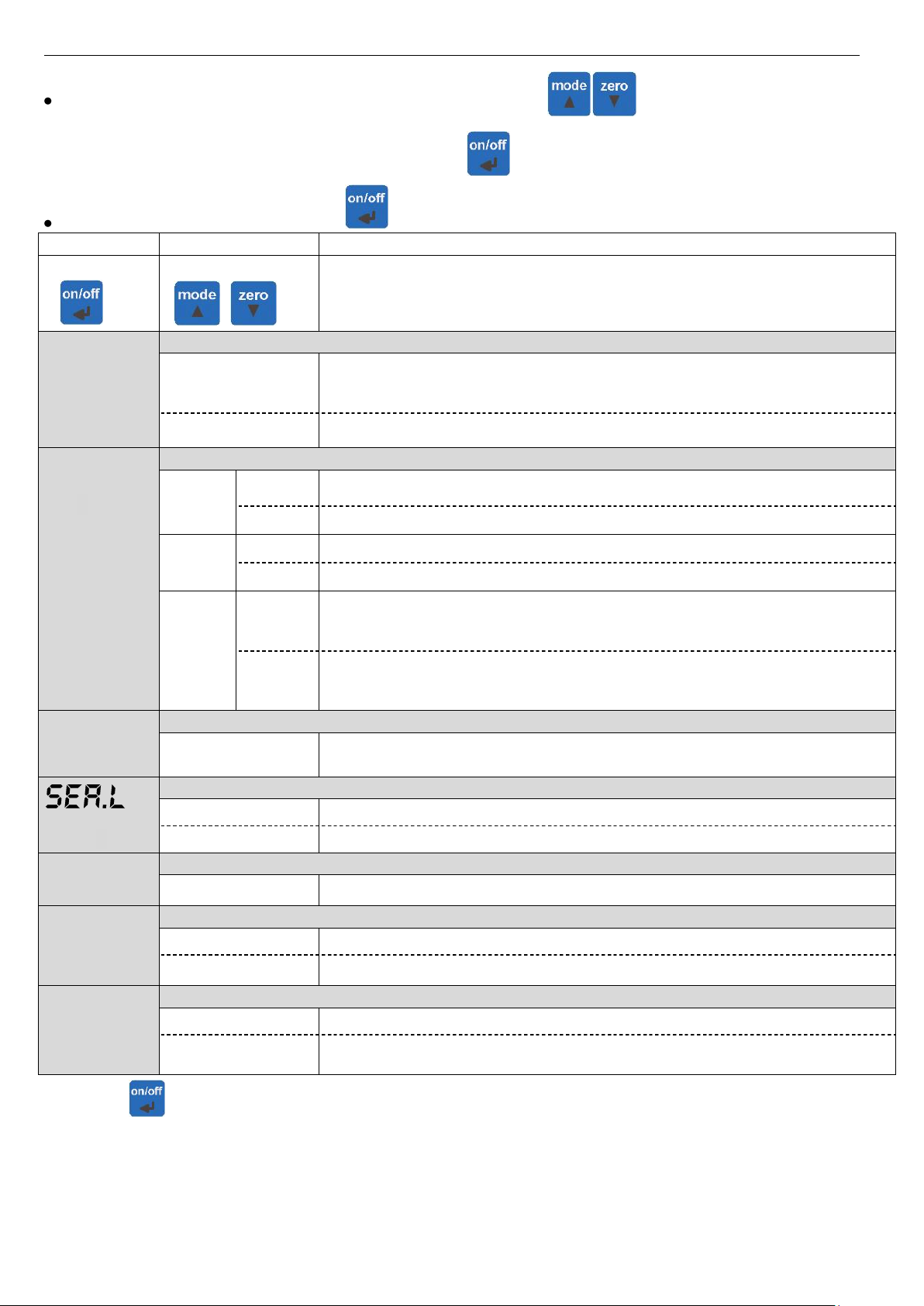
11 Configuration of the device
Follow these instruction to configure the functions of the device:
Switch the device off.
Press mode button and keep it pressed. Turn the device on. Release the mode button after the
segment test ( ) finished. The first parameter “P.OFF“ is displayed.
H55.0.01.6C-07 Operating Manual GTD 1100 page 6 of 8
_____________________________________________________ _____________________________________________________________________________
If a parameter should be changed press key up or down ( ) the present setting of the
parameter will be shown and can be changed via up/down keys.
The parameter setting is confirmed by pressing .
Jump to the next parameter with .
Parameter
value
information
button
buttons
P.OFF
Auto Power-Off (turn-off delay) factory setting: 20 min.
1 …120
Auto Power-Off (turn-off delay) in minutes. If no key is pressed for the
time adjusted in this parameter, the device is automatically switched off to
safe battery power. (adjustable range 1 to 120 min)
OFF
automatic power-off is deactivated (continuous operating)
UN,T
Unit and range of display Dependent of The Slide Switch Position
baro
hPA
10.0 … 1200.0 hPa, resolution 0.1 hPA
nnHG
7.5 … 900.0 mmHg, resolution 0.1 mmHG
temp
°C
-10.0 … +50.0 °C, resolution 0.1 °C
°F
-13.0 …+122.0°F, resolution 0.1 °F
alti
n (m)
-500 … -200 m, resolution 1m
-199.5 … +1999.,5 m, resolution 0.5m
2000 … 9000 m, resolution 1m
Ft (feet)
-1640 … -655 ft, resolution ~5ft
-654 … +1999 ft, resolution ~2ft
2000 … 19999 ft, resolution ~5ft
TREF
Reference temperature for altitude measuring factory setting: +15°C
-25.0 … 50°.0C
-13.0 … 122.0 °F
Reference temperature for altitude measuring
only for slide switch at „alti“
Sea-level correction factory setting: off
OFF
Sea-level correction off
ON
Sea-level correction on
ALT,
Altitude input for sea-level correction factory setting: 340
-500 … 9000
-500 … 9000 m selectable
TEND
Tendency display for barometer
ON
Tendency on
OFF
Tendency off
IN,T
Reset settings to Ex-Works
NO
Settings are kept
YES
Settings of configuration and adjustment menue are reset to ex-works
settings
Pressing again stores the settings, the instruments restarts (segment test)
Please note: If there is no key pressed within the menu mode within 2 minutes, the
configuration will be cancelled, the entered settings are lost!
H55.0.01.6C-07 Operating Manual GTD 1100 page 7 of 8
_____________________________________________________ _____________________________________________________________________________
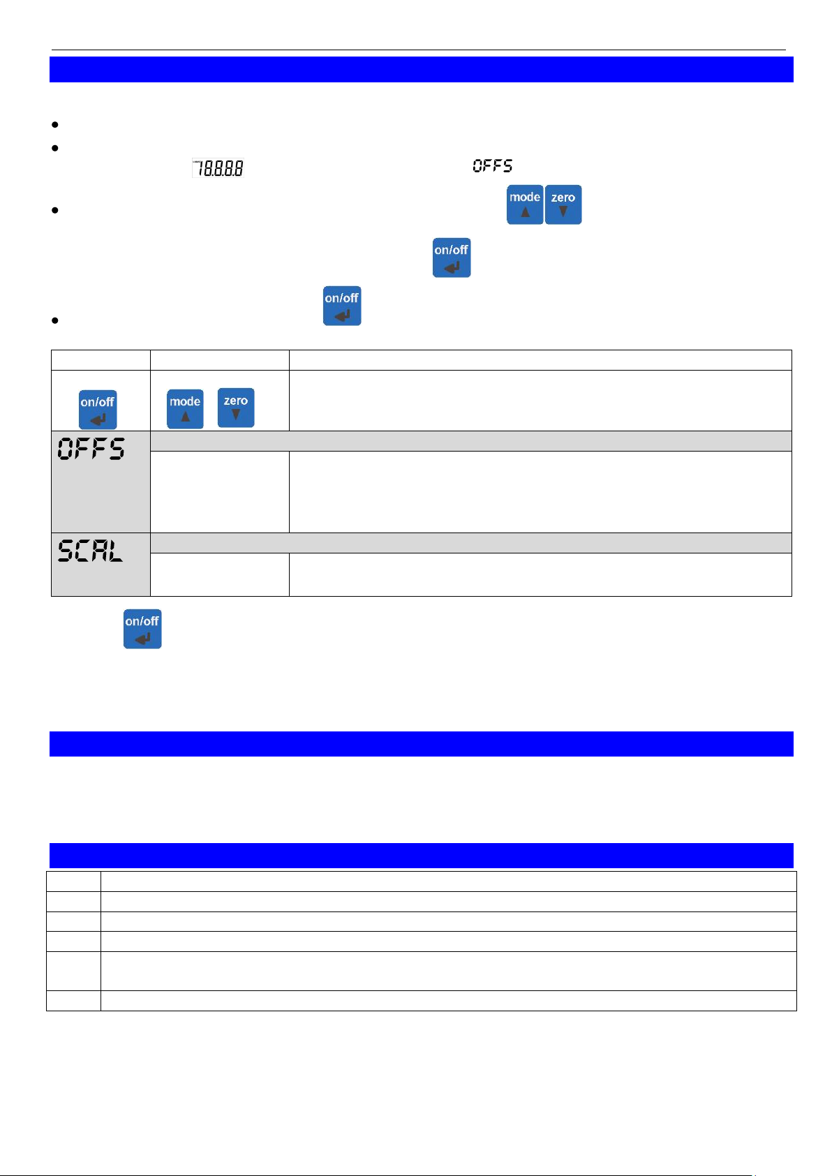
12 Adjustment of the instrument
To adjust the instruments according to your needs proceed like follows:
Switch instrument off.
Press zero button and keep it pressed. Turn the device on. Release the mode button after the
segment test ( ) finished. The first parameter “ ”is displayed.
If a parameter should be changed press key up or down ( ) the present setting of the
parameter will be shown and can be changed via up/down keys.
The parameter setting is confirmed by pressing .
Jump to the next parameter with .
Parameter
value
information
button
buttons
Offset of sensor s factory setting: off
OFF
-5.0 … +5.0
-3.7 … +3.7
-9.0 … +9.0
Adjustment have an effect on
°C, hPa,
mmHg
°F
Scale correction factory setting: off = 0%
OFF
-5.00 … +5.00
Adjustment in %
Pressing again stores the settings, the instruments restarts (segment test)
Please note: If there is no key pressed within the menu mode within 2 minutes, the
adjusting will be cancelled, the entered settings are lost!
13 Notes to the calibration services
Calibration certificates - DKD-certificates - other certificates:
If device should be certificated for its accuracy, it is the best solution to return it with the referring sensors to
the manufacturer. (please state desired test values, e.g. 1bar abs)
Only the manufacturer is capable to do efficient recalibration if necessary to get results of highest accuracy!
14 Error and system messages
Er. 1
measuring range has been exceeded
Er. 2
measured value has fallen below permitted range
Er. 3
display range has been exceeded (>19999)
Er. 4
measuring value has fallen below displayable range (< -1999)
Er. 7
System fault - the device has detected a system fault (defective or far outside allowable
ambient temperature range)
Er.11
Sensor error or value could not be calculated
If the symbol “LOBAT” is displayed at the left side of display, the battery is weak, measuring can be
continued for a short time.
If “bAt” is displayed in the display the battery is used up and needs to be replaced. Measuring is no
more possible.

H55.0.01.6C-07 Operating Manual GTD 1100 page 8 of 8
_____________________________________________________ _____________________________________________________________________________
15 Specification
Meas. range
Abs. Pressure
10.0 ... 1200.0 hPa abs =(mbar abs), resolution: 0.1 hPa
7.5 ... 900.0 mmHg abs., resolution: 0.1 mmHg
Temperature
-10.0 … +50,0 °C, resolution: 0.1 °C
-13.0 …+122.0°F, resolution: 0.1 °F
Altitude:
-500 … -200 m, resolution: 1m
-199.5 … +1999.5 m, resolution: 0.5m
2000 … 9000 m, resolution: 1m
-1640 … -655 ft, resolution: ~5ft
-654 … +1999 ft, resolution: ~2ft
2000 … 19999 ft, resolution: ~5ft
Accuracy: (±1 digit)
(at nominal temperature = 25°C)
Temperature: ±0.05% of measured value ±0.5% FS
Abs. Pressure: ±1.5 hPa (750...1100 hPa)
with calibration certificate: ±0.5 hPa (750...1100 hPa)
height determination: see accuracy of height determination
Max. overload:
6000 hPa abs.
Pressure connection:
sensor integrated in device
Measuring frequency:
1 measurement per second
Offset and scale:
digital offset and scale adjustment for air pressure measurement
Min-/max-value memory:
min- and max- value are stored
Sea level correction:
The displayed value can be referenced to sea level. Therefore the
current height above sea level has to be entered.
Sum-functions:
Only for altimeter: The covered altitude distance is calculated
(ascent, descent, sum) resolution 2m
Tendency:
Only for barometer: display of falling/rising pressure
Zero-function:
relative measurement: the displayed value is set to “zero”
Display:
approx. 13 mm high, 4½-digit LCD display
Pushbuttons:
3 membrane keys for on/off, min-/max-value request,
offset adjustment
Working conditions:
-10 to 50 °C; 0 to 80 % RH (non condensing)
Storage temperature:
-20 to 70 °C
Power supply:
9V-battery, typ. 6F22 (included in scope of delivery)
Current consumption:
ca. 50 µA (Operating time with standard zinc-carbon battery
>6000 hours
Display for weak battery:
automatically if battery consumed "BAT", warning: "LOBAT"
Auto-off function:
If activated: device will be automatically switched off if not operated
for longer time (selectable 1..120min)
Housing:
impact resistant ABS housing, front side IP65
Dimensions:
approx. 106 x 67 x 30 mm (H x W x D) , without connecting nozzle
Weight:
approx. 135g incl. battery
EMC:
The device corresponds to the essential protection ratings
established in the Directives of the European Parliament and the
council on the approximation of the laws of the member states
relating to the electromagnetic compatibility (2004/108/EG).
Additional error: <1%
Table of contents
Other GREISINGER Weather Station manuals


