GRG Banking CA-10 User manual

CA-10
Fast Deposit Module
User Manual
No.:
Version: V1.0
Issued on: September 2017

Fast Deposit Module CA10 User Manual
Confidential material of GRG, No disclosure to unauthorized Party I / II
Document History
No. and name
Version
Date
Revision
description
Personnel involved
Fast Deposit Module
CA-10 User Manual
V1.0
2017.09
Created
Prepared: Dai Xiaowei,
Huang Changyan
Approved by: Wang
Yunlong, Zhang Enfu
Fast Deposit Module
CA-10 User Manual
V1.1
2018.03
Match with
new Toolplus
Prepared:Liu Peng
Approved: Zhang Enfu

Fast Deposit Module CA10 User Manual
Confidential material of GRG, No disclosure to unauthorized Party II / II
Document History................................................................................................................... I
Chapter 1 Overview..................................................................................................................1
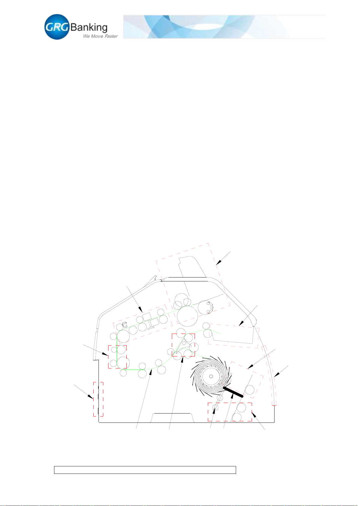
1. Composition..............................................................................................................1
2. Technical parameters ................................................................................................2
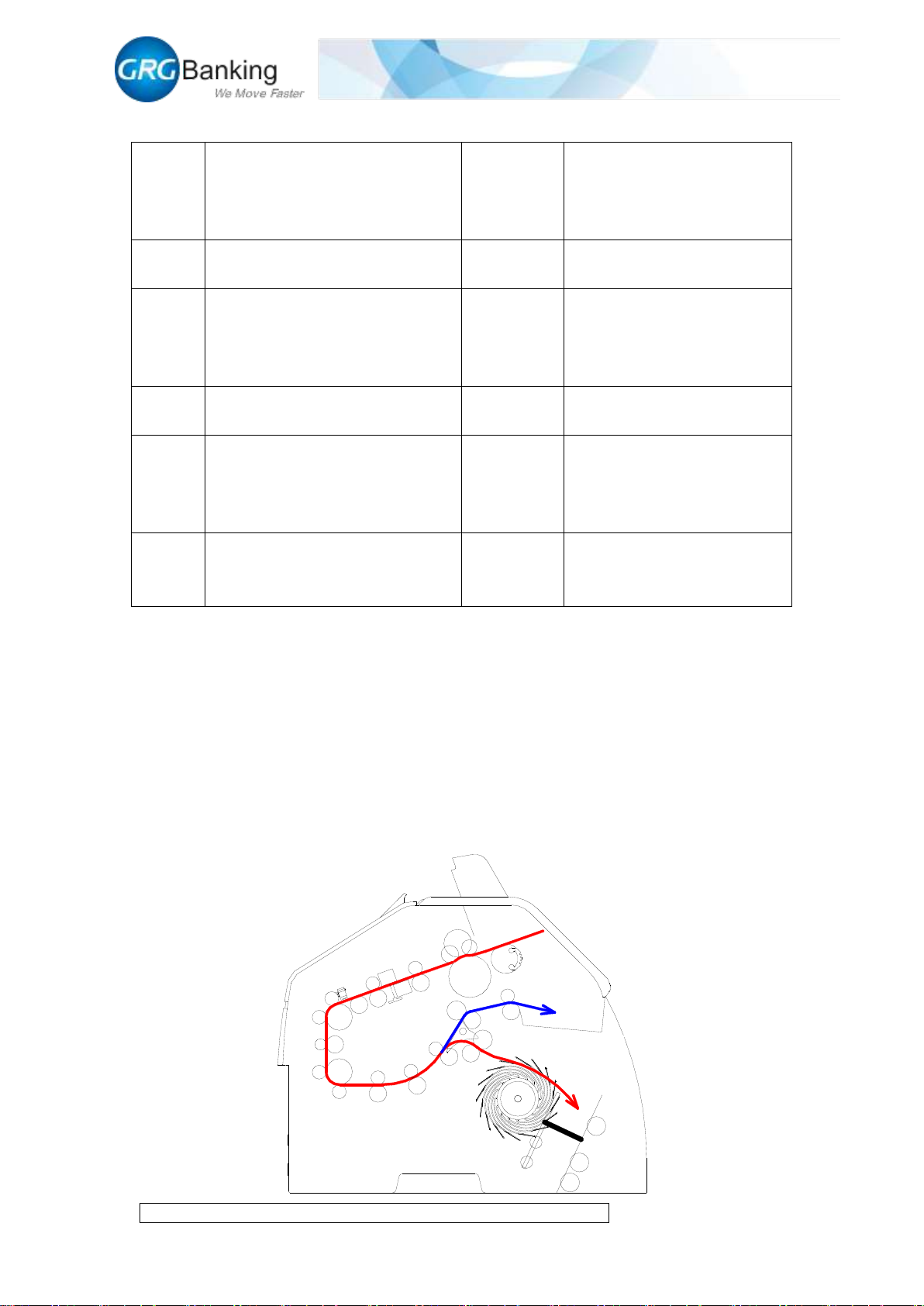
3. Note processing procedure........................................................................................2
3.1 Loading procedure ............................................................................................2
3.2 Pre-deposit process............................................................................................3
3.3 Deposit process .................................................................................................3
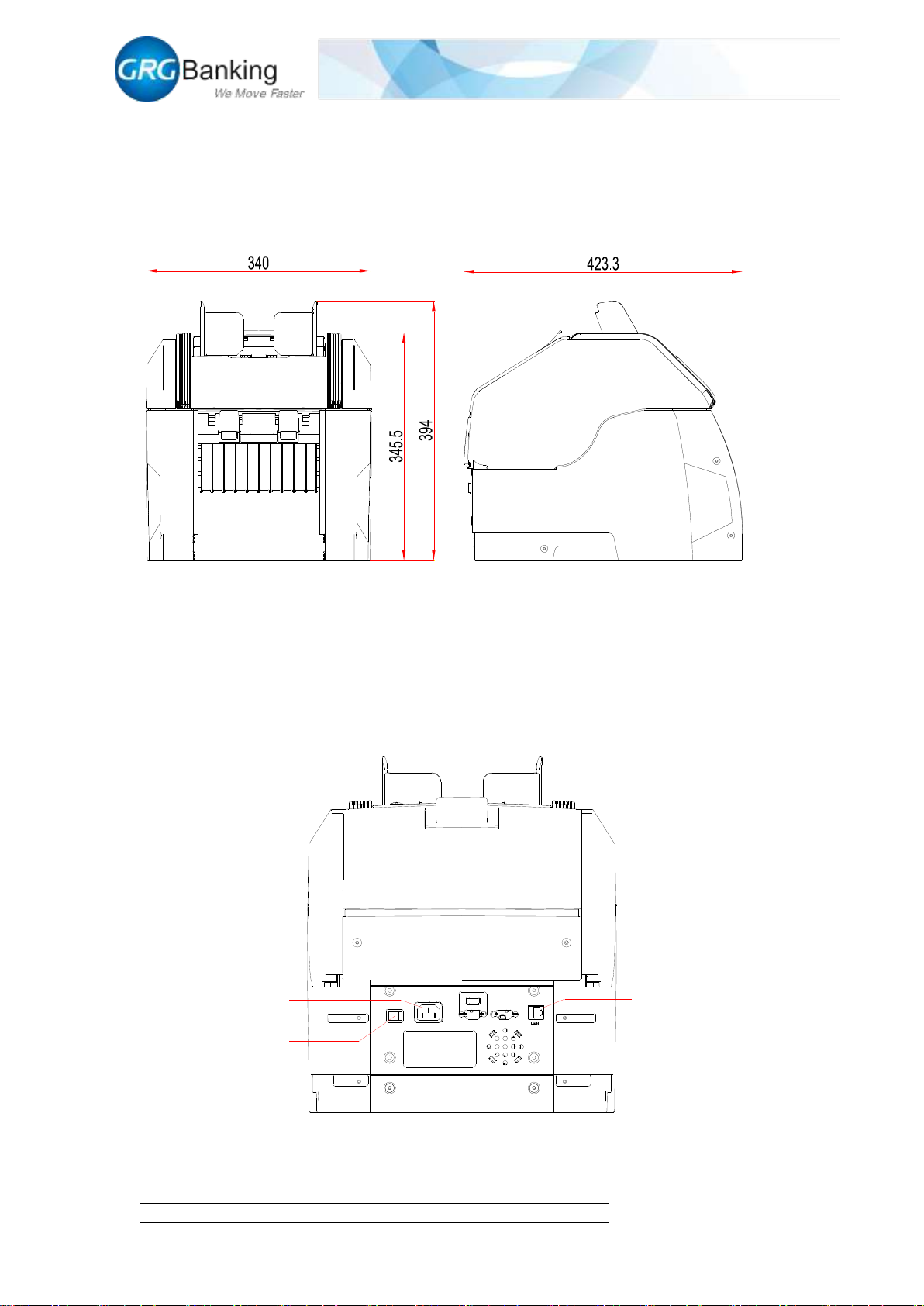
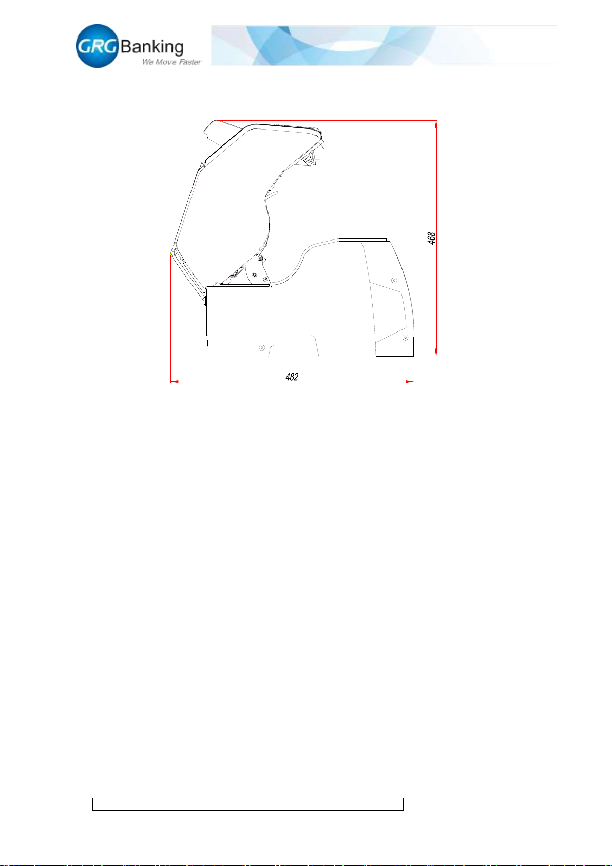
Chapter 2 Overall Dimensions and Wiring...............................................................................5
1. Overall dimensions....................................................................................................5
2. Wiring .......................................................................................................................5
Chapter 3 Installation................................................................................................................6
1. Installation dimensions..............................................................................................6
2. Maintenance space requirements ..............................................................................6
Chapter 4 Method to Debug and Maintain CA10 with Toolplus..............................................8
1. Install Toolplus .........................................................................................................8
2. Connecting CA10 to PC............................................................................................8
3. Run the Toolplus.....................................................................................................12
4. Upgrade main control board....................................................................................13
5. Upgrade DSP...........................................................................................................16
6. Upgrade FPGA........................................................................................................18
7. View version ...........................................................................................................20
8. Set currency type.....................................................................................................20
9. Set work model .......................................................................................................21
10. Deposit process ...............................................................................................22
11. Get the note information .................................................................................26
12. Compensation image collection......................................................................27
13. Reject image collection...................................................................................28
14. Thickness calibration ......................................................................................28
15. Black and white adjustment ............................................................................29
16. Error code query..............................................................................................30
Chapter 5 CA10 Thickness Adjustment Instructions........................................................31
Chapter 6 CA10 Note Feeding Clearance Adjustment Instructions................................35
Chapter 7 Overall Development Support...........................................................................37

Fast Deposit Module CA10 User Manual
Confidential material of GRG, No disclosure to unauthorized Party 1 / 35
Chapter 1 Overview
1. Composition
As shown in Figure 1-1, the CA-10 module is divided into 10 parts depending on their
functions:
1) Input slot;
2) Note validator;
3) Thickness assembly;
4) Lower transport;
5) Diverter;
6) Reject slot;
7) Escrow slot;
8) External shutter;
9) Output slot;
10) Internal shutter
11) Pressure plate;
12) Connection port;
1
2
3
12
6
7
8
9
5
41011
Figure 1-1

Fast Deposit Module CA10 User Manual
Confidential material of GRG, No disclosure to unauthorized Party 2 / 35
2. Technical parameters
Supported
currency
Support the fourth and fifth sets of all
RMB above 1 yuan (upgrade to
support multinational currencies).
Capacity of
note slots
500 notes for the input slot
(optionally 1,000 notes), 200 notes
for the escrow slot, 100 notes for the
output slot
Loading
speed
720 notes per minute
Operating
environment
0℃~40 ℃20% ~90% RH
(non-condensing)
Continuo
us
replenish
ment
Supported
Dimensions of
supported
envelope
Max. length 178 mm ×width 90 mm
×thickness 15 mm
Slot
quantity
1 input slot, 1 output slot and 1 escrow
slot
Overall
dimensions
Length 423 mm ×Width 3,40 mm ×
Height 394 mm
Power
supply
environm
ent
100-240 VAC, 50/60Hz
Weight
Net weight: 19 kg
Communi
cation
interface
LAN
3. Note processing procedure
3.1 Loading procedure
As shown by the red path in Figure 1-2, the notes fed into the note validator through feeder roller
from the input slot pass through the thickness assembly and arrive at lower transport. The notes
validated as acceptable enter into the escrow slot through the diverter as shown by the red path;
and the notes validated as unacceptable enter into the reject slot through the diverter as shown by
the blue path.

Fast Deposit Module CA10 User Manual
Confidential material of GRG, No disclosure to unauthorized Party 3 / 35
Figure 1-2
3.2 Pre-deposit process
As shown in Figure 1-3, when the notes fed forward the escrow slot reach the specified quantity,
the machine stops note loading and the sensor performs the first detection. If notes are stacked
normally in the escrow slot, the internal shutter moves to the right and the pressure plate presses
the notes forward; if notes have exceptions like bursting notes or are not stacked normally in the
escrow slot, the external shutter opens automatically, and then it is required to take out the notes
from the escrow slot manually and deposit again.
Figure 1-3
3.3 Deposit process
As shown in Figure 1-4, the pressure plate presses forward the notes and the sensor performs the
second detection. If notes are stacked normally in the escrow slot, the delivery roller rotates
anticlockwise, and the notes are delivered to the output slot with the force of the delivery roller; if
notes has exception like bursting notes or are not stacked normally in the escrow slot, the internal
shutter moves to the left, and the pressure plate returns back and the external shutter opens. Then
it is required to take out the notes from the escrow slot manually and deposit again.

Fast Deposit Module CA10 User Manual
Confidential material of GRG, No disclosure to unauthorized Party 4 / 35
Figure 1-4

Fast Deposit Module CA10 User Manual
Confidential material of GRG, No disclosure to unauthorized Party 5 / 35
Chapter 2 Overall Dimensions and Wiring
1. Overall dimensions
The overall dimensions are shown in Figure 2.1:
Figure 2-1
2. Wiring
As shown in Figure 2-2, the external interfaces of CA-10 module are divided into power interface
and communication interface, in which the power supply is 100-240VAC and the communication
is realized by RJ45 cable which is used to control data interaction and transmission.
Figure 2-2
Power interface
Power switch
RJ45 cable interface

Fast Deposit Module CA10 User Manual
Confidential material of GRG, No disclosure to unauthorized Party 6 / 35
Chapter 3 Installation
1. Installation dimensions
Refer to Figure 3-1 for the dimensions of mounting holes, and fix the bottom of the CA10.
Figure 3-1
2. Maintenance space requirements
To facilitate the overall cleaning and maintenance, it is necessary to reserve enough space in
Output slot size

Fast Deposit Module CA10 User Manual
Confidential material of GRG, No disclosure to unauthorized Party 7 / 35
advance. As shown in Figure 3-2, turn up the upper transport of CA10 to clean the space required
for maintenance.
Figure 3-2

Fast Deposit Module CA10 User Manual
Confidential material of GRG, No disclosure to unauthorized Party 8 / 35
Chapter 4 Method to Debug and Maintain CA10 with Toolplus
1. Install Toolplus
As shown in the figure below, double click “ToolplusSetup(CA10)_Vx.xxBxxxx”, Vx.xxBxxxx
means version, click “next” until finish installation, default language is English.
Double click to run the test tool “CA10_ToolPlus”, , (note: for Windows XP operating
system, it is required to remove the .manifest file under the installation directory to run the tool
normally after installation).
2. Connecting CA10 to PC
2.1 Connecting to PC with cable
The IP address of CA10 is set by default upon the delivery from factory (IP address: 192.168.1.12,
Port: 7500).
Connect CA10 to PC with the RJ45 cable and modify the “Local Connection” IP address for PC
as shown in Figure 4-1 in which the number “52” also can be other numbers except for “12”.

Fast Deposit Module CA10 User Manual
Confidential material of GRG, No disclosure to unauthorized Party 9 / 35
Figure 4-1
2.2 Connecting to PC by local area network
1) To connect CA10 to PC by local area network, first obtain the “Local Connection” IP address
for PC in local area network.
2) Using the method in 2.1 mentioned above to connect CA10 with PC, click “System CMD”
and “Set IP”, write the same IP address as that of “Local Connection” for PC in the pop-up setting
box, but the number “12” cannot be same for other PCs in the local area network, click “OK” to
display the successful interface and click “OK” again.

Fast Deposit Module CA10 User Manual
Confidential material of GRG, No disclosure to unauthorized Party 10 / 35

Fast Deposit Module CA10 User Manual
Confidential material of GRG, No disclosure to unauthorized Party 11 / 35
3) It is same to recover the IP address of local connection and local area network for PC.
Operate “CA10_ToolPlus” again, write the same IP address and port in step 2 and click the
“Connect” button for a successful connection.
2.3 Recovery of default IP address
To recover the default IP address of CA 10 upon the delivery from factory, turn “pin 2” of the dial
switch to “OFF” position on the main control board, and turn it to the “ON” position after hearing
the “beep” three times to finish the reset of IP address.

Fast Deposit Module CA10 User Manual
Confidential material of GRG, No disclosure to unauthorized Party 12 / 35
3. Run the Toolplus
Power on CA10, after hearing three “beep” sound,then click the “Connect” button , CA10 will
connect with PC automatically (If there is no the “beep”, click the “Connect” button about 15
seconds later after powering on CA10); display “ModuleSN=BOC17/GRG/CA1000000001” in
the “Message” area for a successful connection. Otherwise, display the error information in the

Fast Deposit Module CA10 User Manual
Confidential material of GRG, No disclosure to unauthorized Party 13 / 35
“Message” area and continue the operation below after the error information is excluded; check
the sensor states which should be same as the area of “Sensor State” in the following figure to
show the sensors working normally.
Click the “Init” button to initialize CA10 successfully and display “Success” in the “Massage”
area.
4. Upgrade main control board
4.1 Online download
Click the “Upgrade” button;

Fast Deposit Module CA10 User Manual
Confidential material of GRG, No disclosure to unauthorized Party 14 / 35
Pitch on the upgrade package of the main control board and then click the “Open” button;
Then it will pop up confirm interface, click “yes” to automatically finish firmware update until the
appearance of “Upgrade success”, click “yes” it will automatically re-connect with CA-10, but if
the connection is failed, please click the “Connect” button and reconnect to PC.

Fast Deposit Module CA10 User Manual
Confidential material of GRG, No disclosure to unauthorized Party 15 / 35
4.2 Power-off download (must apply this method when CA10 is unavailable for the lost of the
main control firmware)
Power off CA10 device, copy the main control upgrade file (YT2.480.0618CX_....S) to the root
directory of the USB flash disk, and insert the disk into the U slot on NV board, as shown in the
figure below:
Turn pin 1 of the dial switch on the main control board to OFF position, see the following figure:

Fast Deposit Module CA10 User Manual
Confidential material of GRG, No disclosure to unauthorized Party 16 / 35
Power on CA10 to upgrade the main control program automatically and rotate the CA10 motor
automatically after the upgrade.
Remove the USB flash disk and turn pin 1 of the dial switch on the main control board to ON
position.
Restart CA10 and connect to PC, view the version and contrast the main control version using the
method of step 7 below. If the version is same as the upgrade file version, it indicates that the
upgrade is successful. If failed, please operate as above again.
5. Upgrade DSP
Click the “Upgrade” button;
Pitch on the upgrade package of DSP and then click the “Open” button;

Fast Deposit Module CA10 User Manual
Confidential material of GRG, No disclosure to unauthorized Party 17 / 35
Then it will pop up confirm interface, click “yes” to automatically finish DSP update until the
appearance of “Upgrade success”, click “yes” it will automatically re-connect with CA-10, but if
the connection is failed, please click the “Connect” button and reconnect to PC.
Table of contents
Other GRG Banking Control Unit manuals
Popular Control Unit manuals by other brands

Leadshine
Leadshine DM805-AI Hardware installation manual

Tech Controllers
Tech Controllers EU-L-X WiFi user manual

Lorenz
Lorenz ZWN-RSM2 installation instructions

JM Concept
JM Concept EOLIS 3000 Series user manual

G.R.A.S.
G.R.A.S. 12HM instruction manual

Siemens
Siemens CLM Series Instructions & installation