-4- © 2002 Grizzly Industrial, Inc.
Dial Lock
Loosening the dial lock allows the dial face to
be rotated. This can be helpful when an absolute
measurement is desired and changing the adjust-
ments to the column, boom and fine adjustment
knob are difficult or impractical. In Figure 9 the
dial face has been rotated.
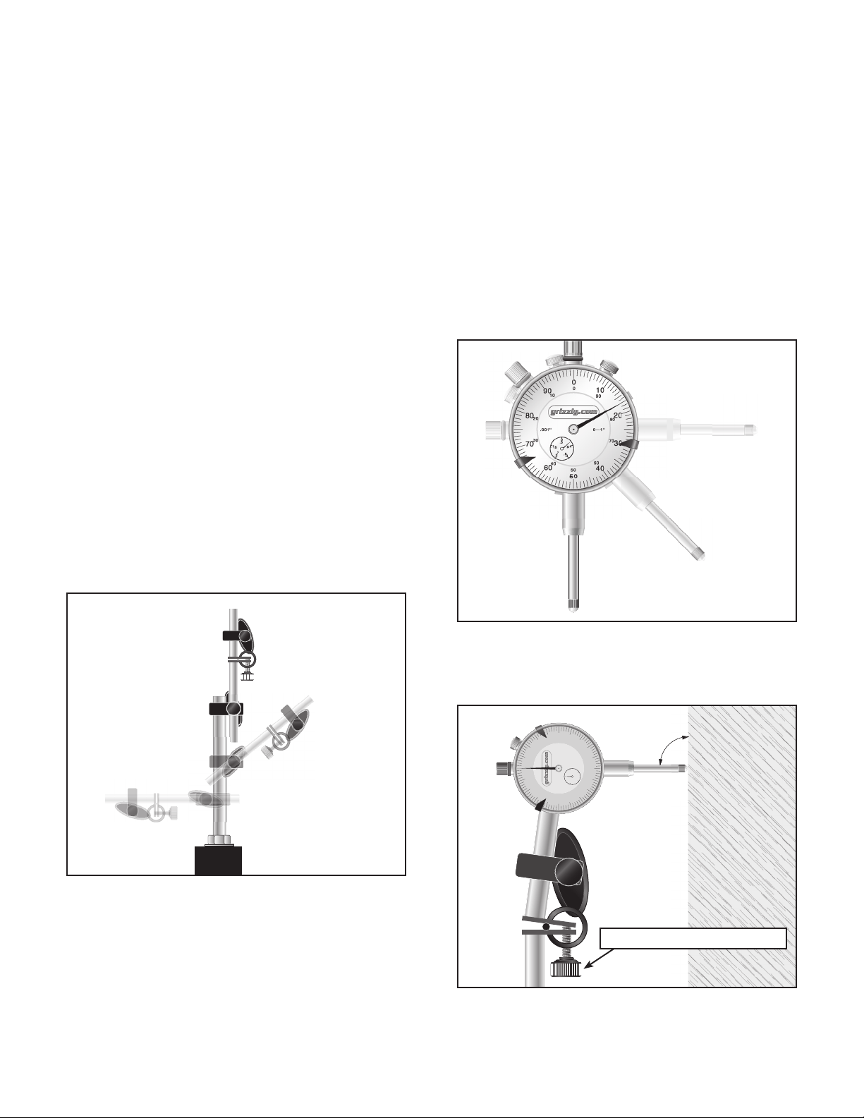
Setting the Contact Point
One of the most important setup issues with a
dial indicator is to make sure the contact point
is perpendicular to its expected motion or to
the motion of the object to be tested. Failure to
ensure proper setup will result in an error in mea-
surement. Please refer to Figure 7 and 8.
Another important note about setup is that the
contact point must be resting against the part
before any change can be indicated. It is there-
fore necessary to adjust the unit so the needle
has moved to ensure a proper measurement.
Use the fine-tune adjustment knob illustrated in
Figure 7.
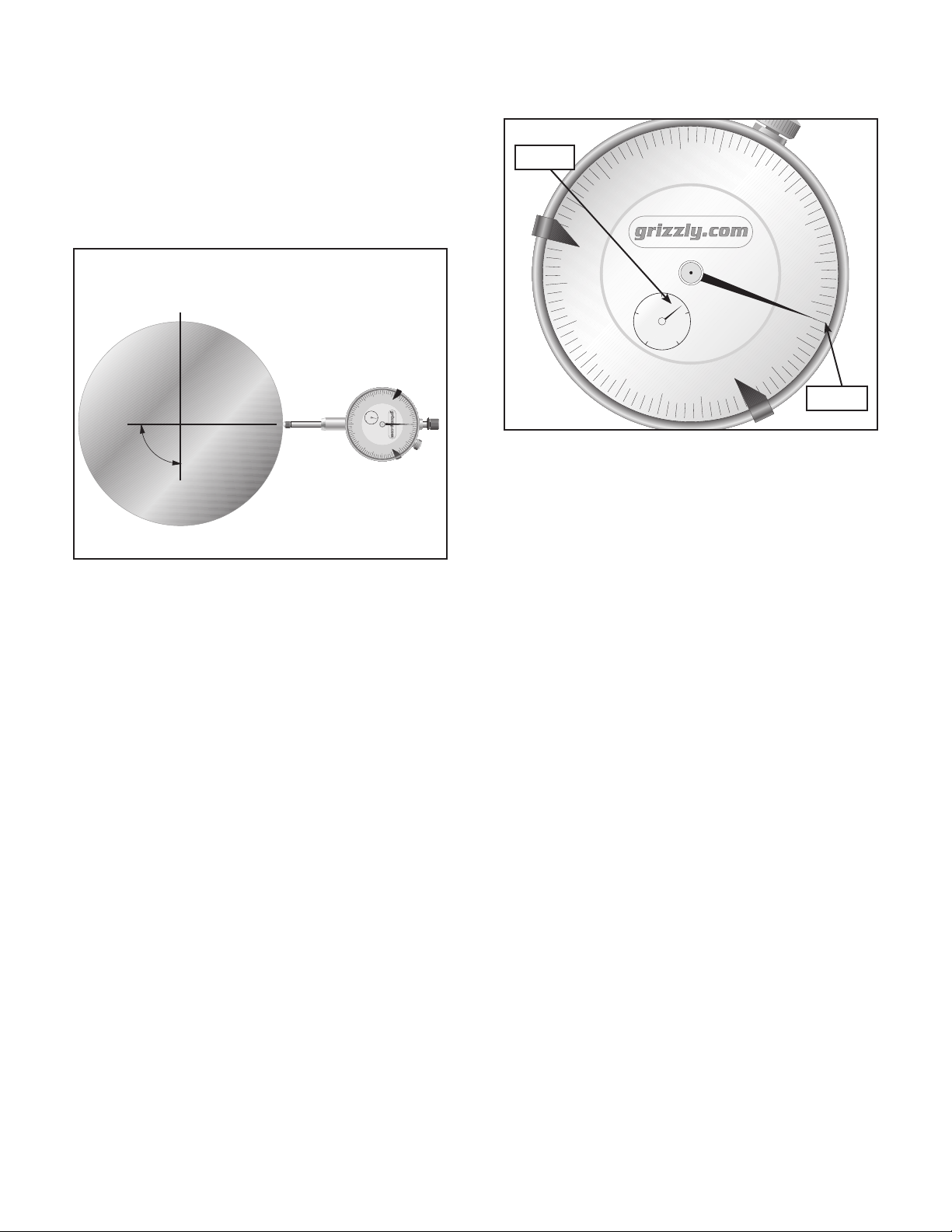
Reading the Dial
Adjustable Markers
The dial indicator is calibrated to read 0.001" and
has a range of 1". When the contact point is not
touching anything, the pointers for each dial will
read “under” the zero inch mark.
It is important to understand that the pointers
rotate in opposite directions as the contact point
is depressed. The pointer for the large dial rotates
clockwise and the pointer for the smaller dial
rotates counterclockwise when the contact point
is depressed. You must keep track of the number
of revolutions for the smaller dial! The first revolu-
tion is indicated by the numbers on the outer ring
of the numbers and the second revolution is indi-
cated by the innermost numbers. The example in
Figure 9 indicates 0.417".
As with the decade counter, the main dial has
a second set of numbers. These can be used
to keep track of the actual motion of the contact
point when it is released.
The dial indicator can also be set up to be used
as a range tester. There are 2 adjustable mark-
ers that can be positioned on the dial face. A
range can then be checked. In the example in
Figure 9, the adjustable markers have been set
to measure between 0.030" and 0.065". Again, if
a larger range than 0.100" is needed, the revolu-
tions of the pointer on the smaller dial will have
to be counted.
10
20
30
40
50
60
70
80
90
0
0
.5
.4
.9
.3
.8
.2
.7
.1
.6
.001'' 0—1''
20
10 90
80
70
60
50
40
30
0
Figure 9. The dial reads 0.417".
10
20
30
40
50
60
70
80
90
0
0
.5
.4
.9
.3
.8
.2
.7
.1
.6
.001'' 0—1''
20
10 90
80
70
60
50
40
30
0
C
L
90˚
Figure 8. The indicator is positioned perpendic-
ular to the axis of a round bar. When the bar is
turned, the runout or lateral motion is indicated
by motion of the needle.
0.400"
0.017"
462402622