Grodan
8
Grodan
9
Installation Manual Installation Manual
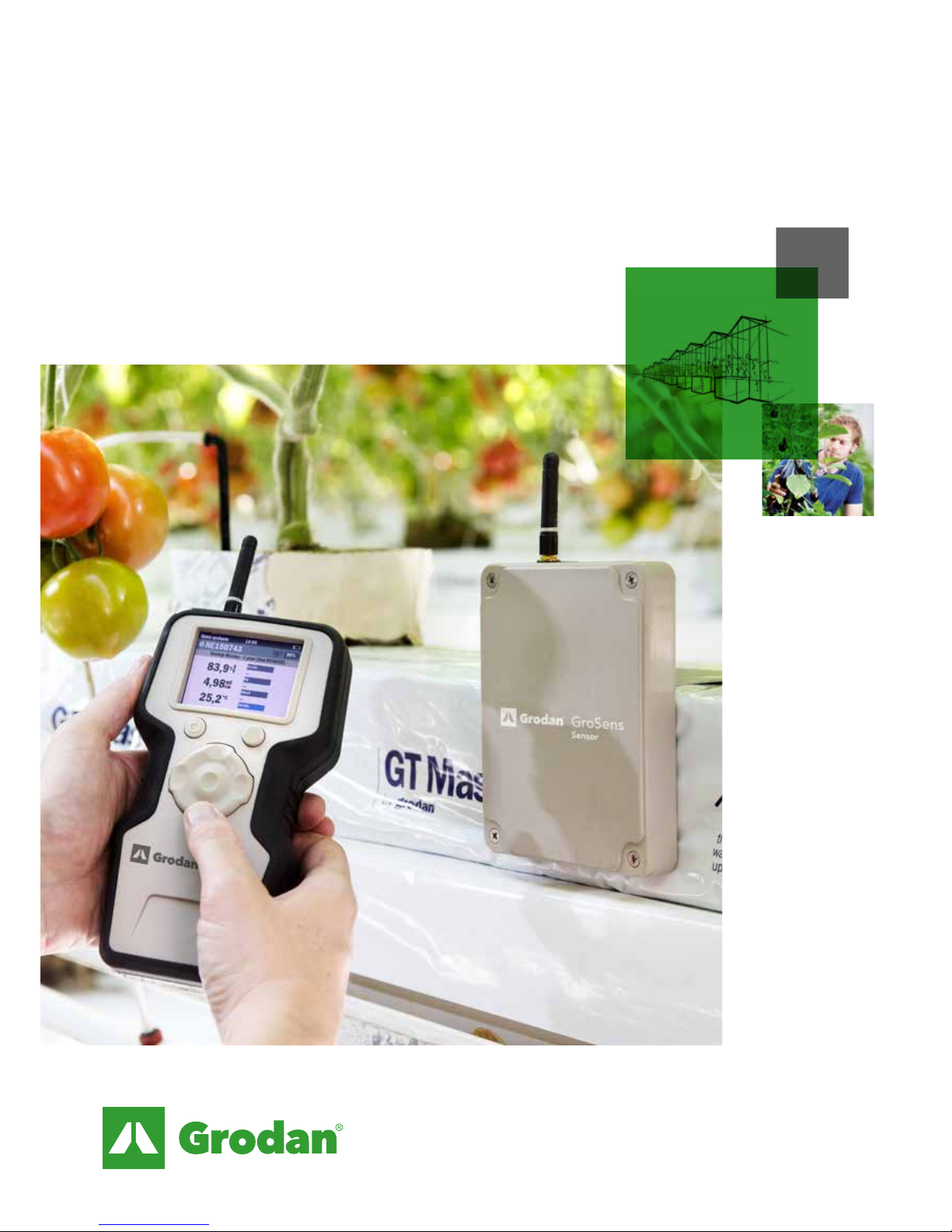
2.5 GroSens Sensors
The GroSens Sensors need to be positioned within a
50 metre radius of the GroSens Receiver. The following
steps should be taken:
1. Determine roughly the spot where the GroSens
Sensors need to be placed.
2. Perform a set of measurements with the GroSens
Reader close to the chosen spot. See the GroSens
Reader manual for more instructions.
3. Determine a representative location and place a
GroSens Sensor.
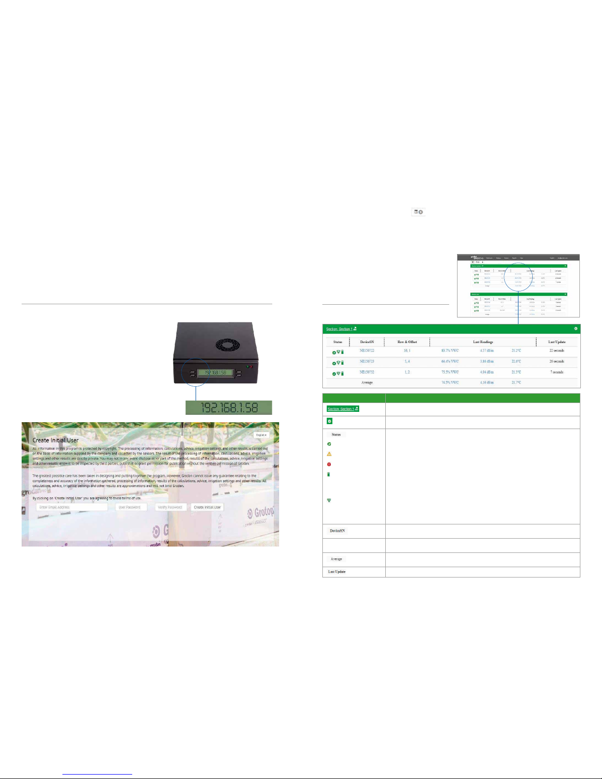
LED’sTEST button
First, the long cable into the greenhouse should be
connected to the Receiver. The correct RJ45 outlet must
be used when connecting the PoE injector to the
GroSens Receiver. The outlet is located inside the
GroSens Receiver housing (see below).
The cable between the PoE injector outside the
greenhouse and the Receiver inside the greenhouse
cannot be longer than 100 metres (see option 1).
StandardEthernetcables:Cat5eissufcient.
If the distance between the PoE injector and the
Receiver is greater than 100 meters, an Extender or
Switchbox must be installed after every 100 metres of
cable (see option 2). There is one Extender provided in
the set. The maximum distance from the PoE Injector to
the Receiver is 200 metres. Extra Extenders to extend
the maximum distance can be ordered from Grodan
Customer Service if required.
When the GroSens Receiver is connected to the PoE
Injector, two LEDs should light up: the Power LED and
Link LED. The Power LED will light up immediately. The
link LED will turn on as soon as the GroSens Receiver
has auto-discovered the GroSens Smartbox; this can
take several minutes. Wait until the Link LED is lit before
continuing the installation process. After the connection
is made, the housing can be closed.
It is best to locate the GroSens Receiver above the
highest point of the crop (at the end of the season).
Position the Sensors in the centre of the area and, for
better wireless reception, as far as possible from steel
poles or other heavy greenhouse structures. Fasten the
Receiver with a tie-wrap or another sort of easily
removable mounting device in case the Receiver needs
to be relocated if the GroSens Sensors get out of range.
Please note: You must install the GroSens Smartbox
rst, as indicated in the installation sequence. The
GroSens Receiver will only connect to a GroSens
Smartbox that is already running. The Receiver requires
24V of power. This can also be realised by using a
standard 24V adaptor. The adapter should output DC
voltage between 12-30 volts, capable of supplying 500
milliamps of current.
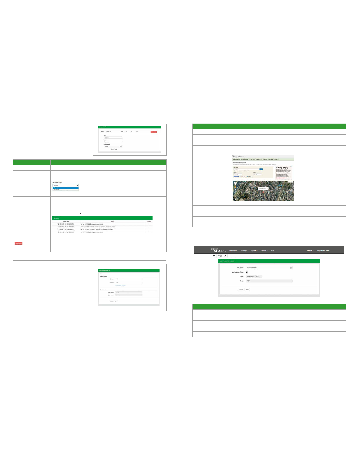
LED’s
GroSens Receiver
4. Activate the GroSens Sensor by pushing the
TEST button. After activation, both LEDs will light
up and, after a few minutes, only the green LED
will glow:
- The green LED indicates round-trip
communication with the GroSens Smartbox.
- The red LED indicates a problem
communicating with the GroSens Smartbox.
5. You will not need to change GroSens Sensor
settings for installation. The settings can be
changed with the GroSens Reader if needed:
- Select your network (i.e. System Identity)
- Go to the Device screen
- Press the TEST button on the Sensor
- Select the Sensor in the list.
Please note: The GroSens Sensors are delivered with 4
fully charged AA batteries installed. The Sensors are in
“hibernate” mode when delivered. Pressing the TEST
button will activate them. It is recommended not to
activate them before installation, as the batteries will
lose their charge.
2.6 How to install the Sensors in the greenhouse
Place a Sensor 8 – 10 cm left from the 2nd block from
the drain hole. The antenna should be placed furthest
away from the 2nd block. This can be found in drawings
on the right..
In case the cropping system is different and the former
mentioned rule cannot be applied, please contact
Grodan Customer Service.
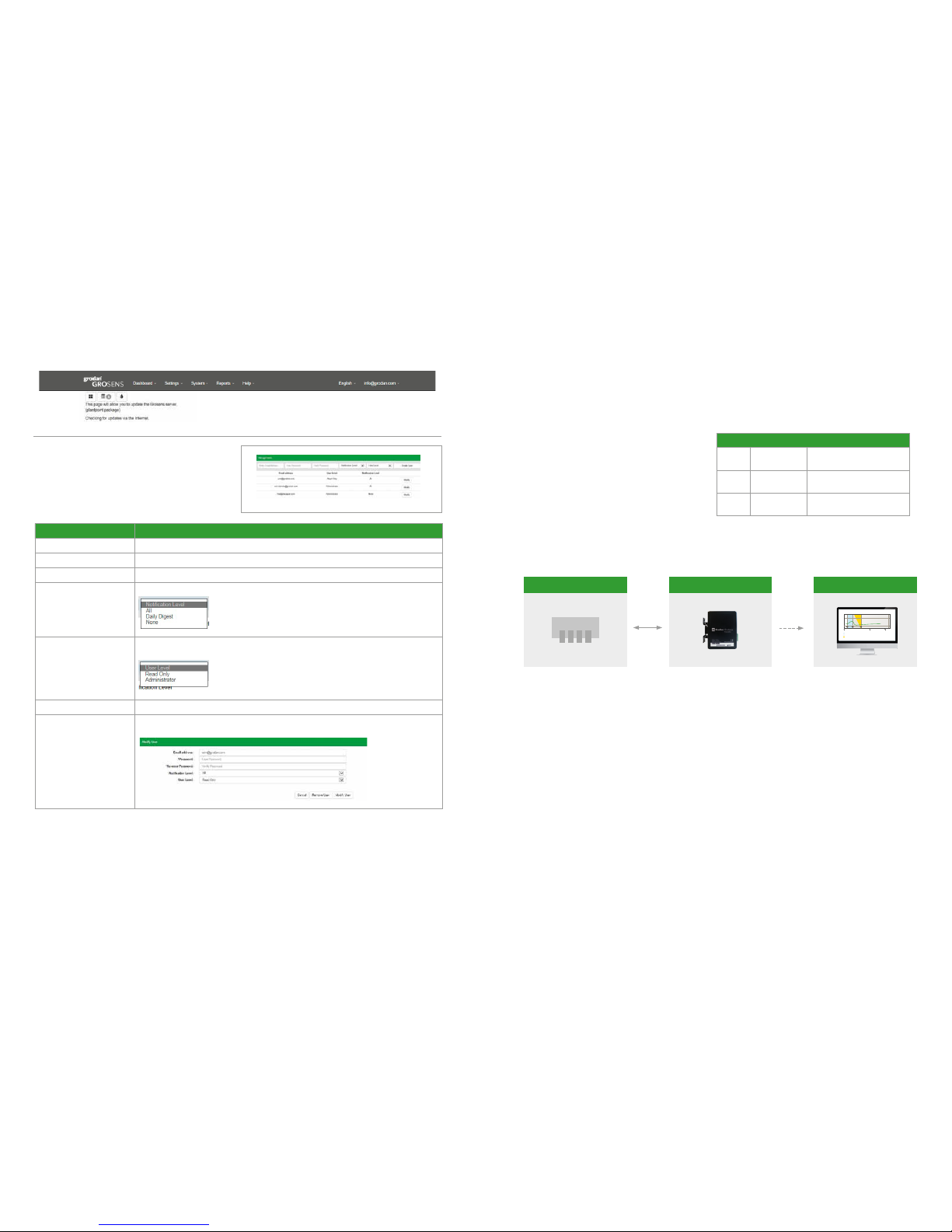
2.7 Setting the correct plate height
For all slabs with a height of 7,5 cm:
• The guiding plate should be positioned in the
lowest position. This is the position the Sensors are
normally delivered to customers. See picture:
For all slabs with a height of 10 cm:
• The guiding plate should be positioned in the
upper position. See picture:
GroSens Sensors
7,5 10