Growatt ML33RTA User manual

Shenzhen Growatt New Energy CO.,LTD
ML33RTA Lithium Ion Standalone Battery
Residential Energy Storage System
Product Manual
Version: V1.0
Date: 2020-10-12

1
Contents
About This Document ............................................................................................................................ 2
1 Important Safety Information ............................................................................................................. 3
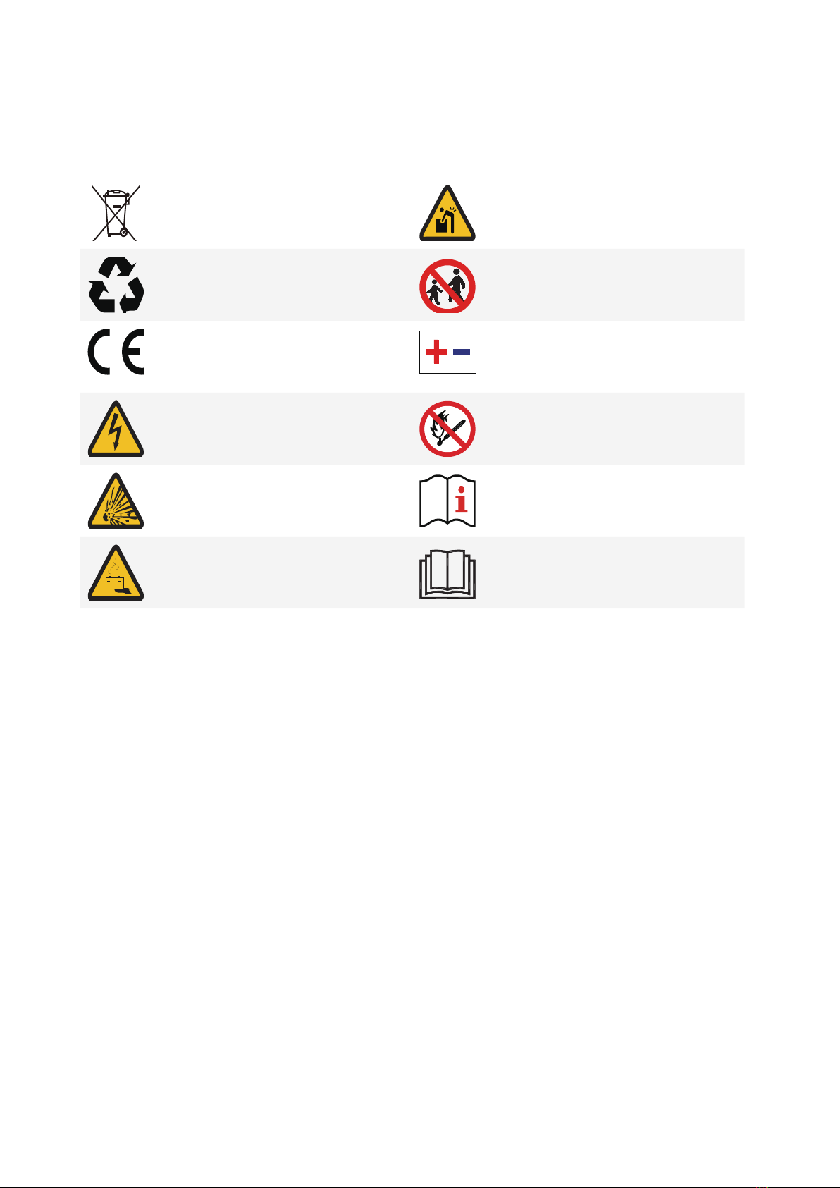
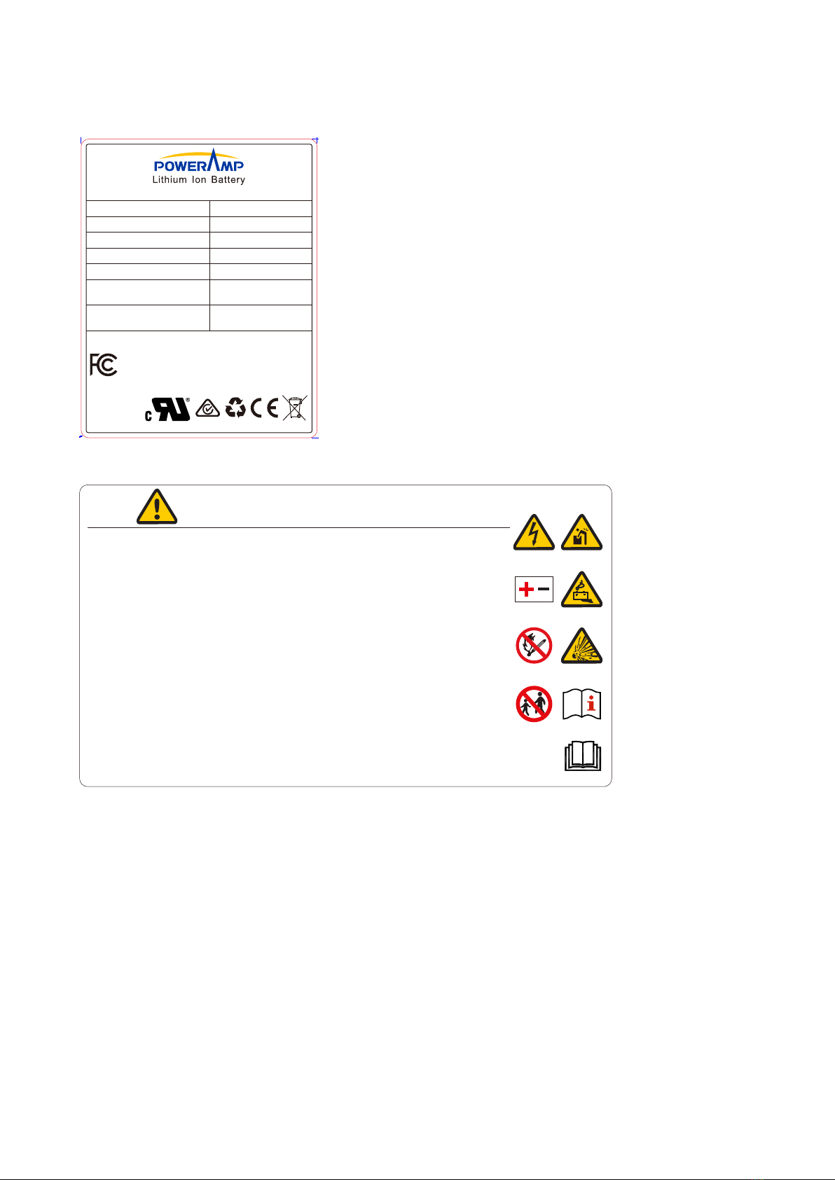
1.1 Warning Label .......................................................................................................................................................3
1.2 Precautions ............................................................................................................................................................3
2 Overview............................................................................................................................................... 6
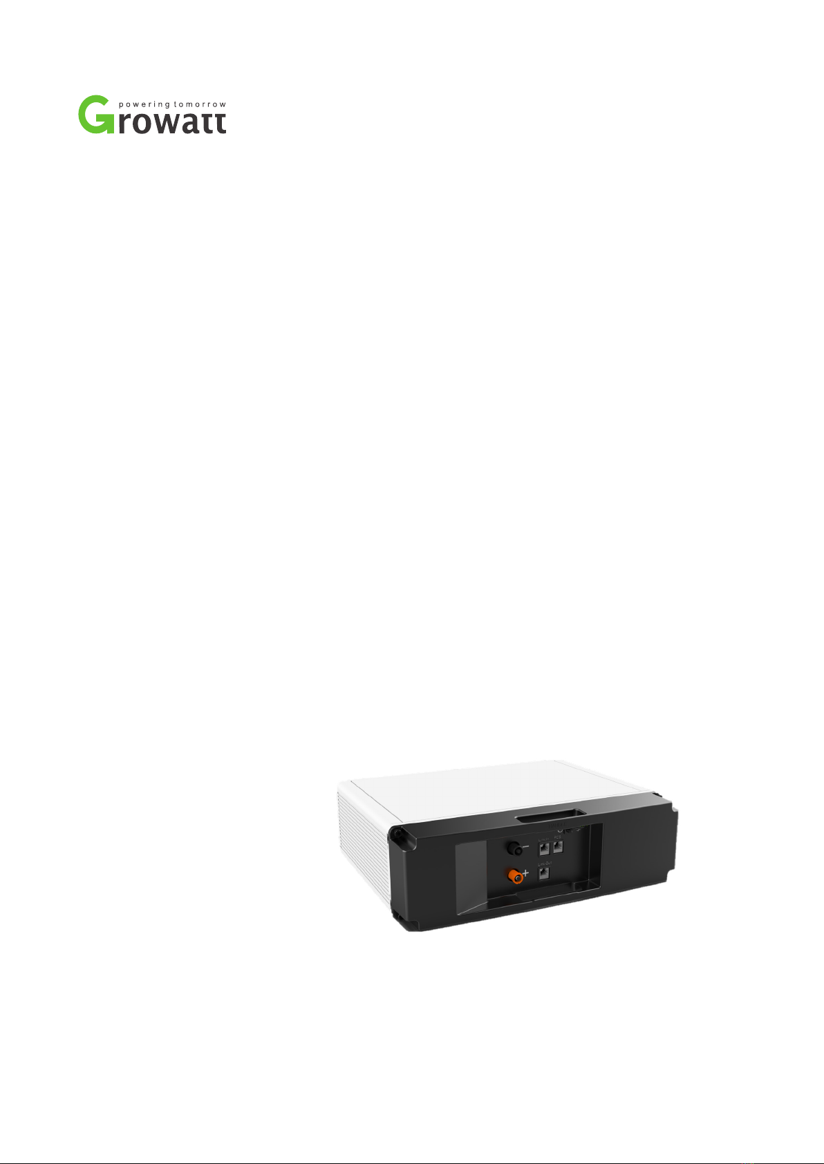
2.1 Appearance and Terminals.....................................................................................................................................6
2.2 Application Scenarios.............................................................................................................................................7
2.3 Technical Parameters.............................................................................................................................................7
3 Storage and Transport ........................................................................................................................ 9
3.1 Storage Requirements ...........................................................................................................................................9
3.2 Transport Requirements.........................................................................................................................................9
4 What You Need .................................................................................................................................. 10
4.1 Tools.................................................................................................................................................................... 10
4.2 Protective equipment .......................................................................................................................................... 10
5 Installation.......................................................................................................................................... 11
5.1 Inspection before Installation ...............................................................................................................................11
5.2 Battery Orientation ...............................................................................................................................................11
5.3 Installation.......................................................................................................................................................... 12
6 Electrical Connection........................................................................................................................ 13
6.1 Power Terminals and Network Ports ................................................................................................................... 13
6.2 Connect One Battery........................................................................................................................................... 13
6.3 Connect Batteries in Parallel............................................................................................................................... 14
7 Operation............................................................................................................................................ 16
7.1 Power on Battery................................................................................................................................................. 16
7.2 Power o Battery................................................................................................................................................. 16
8 Maintenance....................................................................................................................................... 17
8.1 Replace Battery................................................................................................................................................... 17
8.2 Upgrade Firmware .............................................................................................................................................. 17
8.3 Troubleshooting................................................................................................................................................... 19
9 Product Liability ................................................................................................................................ 20
10 Recycle............................................................................................................................................. 21

2
About This Document
Purpose
This document describes the application scenarios, installation, electrical connection, commission and troubleshooting of
ML33RTA, a 3.3 kWh Energy Storage Battery (hereinafter simply put as battery). Before installing and operating battery,
please ensure that you are familiar with product features, functions, and safety precautions as provided in this document.
Target Audience
Installer, operator, commissioning personnel, maintenance personnel of the RESS product
Change History
Version Date Changes Prepared By Reviewed By
1.0 2020-10-08 Initial draft WQ
Guo YH
Wang XP
Ni YL
Symbols and Conventions
Warning and caution messages are listed in the document to remind users, installers and maintainer of safe operation.
Symbol Description
!
WARNING
Indicates a potentially hazardous situation, if not avoided, could result in serious injury or
death.
!
CAUTION
Indicates a potentially hazardous situation, if not avoided, may result in minor or moderate
injury

3
1 Important Safety Information
1.1 Warning Label
Do not dispose battery in household trash. Battery is heavy enough to cause severe
injury.
Recyclable. Keep battery away from children.
Certication in European Union area. Do not reverse polarities.
Risk of electric shock. Do not expose battery to ame.
Explosive gas. Operate as specied by the manual.
Battery may leak corrosive electrolyte. Read the manual before operating.
1.2 Precautions
Risks of electrolyte leakage
* Do not subject battery to strong impact.
* Do not crush or puncture battery.
* Prevent battery from falling. In case of fall, turn o the battery immediately and stop using it.
* Do not open or mutilate batteries. Released electrolyte is harmful to the skin and eyes.
Risks of re
* Do not expose battery to direct sunlight.
* Avoid contact with conductive objects such as wires.
* Keep battery away from re source, inammable, explosive and chemical materials.
* Do not dispose of batteries in a re. The batteries may explode.
Risks of electric shock
* Do not touch battery with wet hands.
* Keep battery away from children and animals.
* A battery can present a risk of electric shock and burns by high short-circuited current.
* Battery installation and wire connection must be operated by professionals.
Risks of damage
* Keep a distance to water source.
* Do not subject battery to high voltage.

4
* Place battery on a at surface. Do not place any foreign object on top of battery nor step on battery.
* Battery-connected PCS should have reinforced insulation.
Table 1-1 Responses to Emergencies
Event Description and recommended actions
Leakage Inhalation: leave the contaminated area right now.
* Swallow: induce vomiting.
* Contact with eyes: ush eyes with owing water for 15 minutes.
* Contact with skin: wash thoroughly with soap and water.
* Immediately seek for medical intervention after taking emergency measures.
Fire Battery may catch re when heated above 150℃.
Please implement the following actions:
* Extinguish fire before the battery catches fire. ABC or carbon dioxide extinguisher is
recommended.
* If the re is too strong to put out, move battery to a safe place before it catches re.
* If battery is on re, evacuate people rst before seeking help from professional re protection
personnel.
* If battery catches fire during charging, turn off the breaker between battery and PCS when
safety can be guaranteed.
Wet battery If battery became wet or has been submerged in water, do not access it. Immediately contact your
distributor for technical assistance.
Damage Damaged battery is dangerous and must be handled with utmost care. They are not usable for use
and could pose a safety threat to people or property. If battery is suspected to be damaged, stop any
operation and return it to distributor.

5
Nameplate
R2
*76±0.5
*60±0.5
Model:
Nominal Voltage:
Total/Rated Capacity:
Total/Rated Energy:
Ingress Protec�on:
Opera�ng Ambient
Temperature:
Maximum Short Current
and Dura�on:
ML33RTA
51.2V
64Ah/58.6Ah
3276Wh/3000Wh
IP20
-10℃ ~ 50℃
1700A, 2ms
IFpP/16/122/360/[16S]M/-10+50/90
Made In China
This device complies with Part 15 of the FCC
Rules. Operation is subject to the following two
conditions: (1) this device may not cause harmful
interference, and (2) this device must accept any
interference received, including interference that
may cause undesired operation.
Warning Label
WARNING AVERTISSEMENT
1. Do not disassemble or alter the battery in any way.
Ne démontez ni modifiez la batterie en aucune façon.
2. Do not use the battery for purposes not described in its documentation.
N'utilisez pas la batterie à des fins non décrites dans sa documentation.
3. Do not drop, strike, puncture, or step on the battery.
Ne laissez pas tomber, ne heurtez pas, ne percez pas et ne marchez pas sur la batterie.
4. In case of electrolyte leakage, keep leaked electrolyte away from contact
with eyes or skin, immediately clean with water and seek help from a doctor.
En cas de fuite d'électrolyte, gardez l'électrolyte qui fuit loin du contact avec les yeux
ou la peau, nettoyez immédiatement avec de l'eau et demander de l'aide à un médecin.
5. Do not put the battery into a fire. Do not use it or leave it in a place near fire, heaters,
or high temperature sources.
Ne mettez pas la batterie au feu. Ne l'utilisez pas et ne le laissez pas dans un
endroit près de feu, de radiateurs ou de sources de températures élevées.
6. Do not submerge the battery in water, or expose it to moisture.
Ne plongez pas la batterie dans l'eau et ne l'exposez pas à l'humidité.
7. Do not allow the terminals to contact exposed wire or metal.
Ne laissez pas les bornes entrer en contact avec du fil ou du métal exposé.
8. The battery is heavy and can cause injury if not handled safely.
La batterie est lourde et peut provoquer des blessures si elle n'est pas manipulée en toute sécurité.
9. Keep out of reach of children or animals. Tenir hors de portée des enfants ou des animaux.

6
2 Overview
ML33RTA is a 3.3kWh LiFePO4 battery pack. It has a 48V battery module as the main power supply unit which com-
posed of 64Ah cells in one parallel and 16 serial connect (1P16S).
2.1 Appearance and Terminals
The battery is an energy storage unit composed of cells, mechanical parts, battery management system (BMS) as
well as power and signal terminals.
Table 2-1 Mechanical features
Parameter Value
Dimension W445*D131*H399.6 mm
Weight Around 29 kg
Installation Rack-mounted installation
Table 2-2 Ports and terminals
No. Label Name
1 Link-Out Network port 3
2 P+ Positive terminal 1
3 P- Negative terminal 1
4 Link-In Network port 2
5 PCS Network port 1
6 POWER POWER button
LED indicators
Status SOC Indication LED1 LED2 LED3 LED4 LED5
Charging 0%-25.0% ■ ●
25.1%-50.0% ■ ■ ●
50.1%-75.0% ■ ■ ■ ●
75.1%-99.9% ■ ■ ■ ■ ●
100% ● ● ● ● ●
Discharging
& Standby
100%-75.1% ● ● ● ● ●
75.0%-50.1% ● ● ● ●
50.0%-25.1% ● ● ●
25.0%-0% ● ●
445
399.6
131
LED5
LED4LED3LED2LED1
POWER
345
1
2

7
★: Blue LED Blink ●: Blue LED On ■: Blue LED ash display
2.2 Application Scenarios
Battery coordinates with PCS in the residential energy storage system. The typical application scenarios are as shown
below.
Junction BoxJunction Box
The energy produced by PV is optimized to supply loads.
The excess energy is used to charge battery, then export
to grid.
Battery powers loads at nighttime when there is no PV. If
battery energy is insucient, it can supply loads together
with grid.
Junction Box Junction Box
When grid falls, battery and PV can power loads. Battery can be charged by grid. Users are suggested to
store energy from grid to battery when electricity price is
relatively lower.
2.3 Technical Parameters
No. Items Specications
1 Nominal Voltage (V) 51.2V
2 Normal Capacity/Energy 64Ah/3.3kWh
3 Usable Capacity/Energy 58.6Ah/3.0kWh

8
4 Operating Voltage 48 ~ 57.6V
5 Rated Charging Current 32A
5 Rated Discharging Current 42.5A
6 Max. Discharging Power 3kW
7 Peak Discharging Power 4.3kW/5s
8 Max Charging Power 1.5kW
9 IP Protection IP20
10 Working Temperature -10°C~+55°C
11 Storage Temperature -20°C~+45°C
12 DOD 94.5%
13 Cycle Life >3500 (25°C, 60% SOH)
14 Parallel Connection Max .6 packs
15 Communication Port CAN2.0 / RS485
16 Warranty 10 years
17 Certication IEC62619, CE, UN38.3

9
3 Storage and Transport
3.1 Storage Requirements
Battery storage life
Life Temperature Humidity
7 days -30℃to -20℃or 45℃to 60℃5%RH-95%RH
180 days -20℃to 45℃5%RH-95%RH
If the battery is not used for more than 1 week, you need to store it in accordance with the requirement for storage
conditions.
* Place battery according to signs on packing box and do not put battery upside down or sidelong.
* Store batteries in a place free from direct sunlight and rain.
* Keep batteries at least two meters away from a heat source (such as a radiator).
* Avoid contacting with corrosive and organic substances (including gas exposure).
* Batteries with deciencies should be separated from normal batteries by setting wall between or placing in dierence
re protection zones.
* Keep the storage area dry, clean and well ventilated.
* Recharge the battery that has been stored for over 12 months.
Set “CV=55V, CC=16A” and charge the battery till LED2 ickers.
3.2 Transport Requirements
Battery has cleared UN38.3 (Section 38.3 of the Seventh Revised Edition of the Recommendations on the Transport of
Dangerous Goods: Manual of Tests and Criteria) and SN/T 0370.2-2009 (Part 2: Performance Test of the Rules for the
Inspection of packaging for Exporting Dangerous Goods). The battery is classied as class 9 dangerous goods, and is
subject to land and water transportation. It is mandatory to report to the airline company and obtain approval before air
transport.
* Before transportation, press POWER button for two seconds and ve LED lights icker for three times to power o
battery.
* During transportation, put battery at, do not have battery stand on or lean against the oor to avoid possible crash.
* Maintain temperature between -20℃to 45℃ during the transportation.
* Prohibit mixing up with explosive, inammable or toxic objects.
* Use van-type vehicle including container and metallic van-type vehicle. Platform vehicle and convertible are
prohibited.
* Do not pile up foreign objects on the top of battery. Four batteries at most can be piled up.
* Maintain original packaging and keep labels complete and recognizable.
* Prevent from direct sun exposure, rain, condensation and mechanical damages.

10
4 What You Need
Before installing, operating, and maintaining the battery, you need to prepare tools and protection equipment to ensure
safety.
4.1 Tools
FUSED
FUSED
1000VMAX
10A 100mA COM
VΩ
OFF
V
A
A
V
Ω
Hz
%
Screwdriver Multi-meter Tape HEX key
4.2 Protective equipment
Insulated gloves Safety goggle Safety shoes
To prevent injury, always wear acid-resistant clothing, PVC gloves, goggles and rubber boots during installation, opera-
tion, and maintenance.

11
5 Installation
It is recommended to install the battery into a cabinet and place it indoor. If you install it outdoor, select a cabinet with a
sucient IP rating. Build sunshade & rain shelter to avoid direct exposure to sunlight and rain for outdoor application.
5.1 Inspection before Installation
Before installation, check carefully for any damages on the package and the products and inspect if all accessories in the
list are included. If any part is missing or damaged, please contact your distributor.
Battery Package
Item NO. Part Name Quantity
1 Battery Pack 1
2 Quick Guidance 1
3 Warranty Card 1
4 Master plug 1
5 Slave plug 1
6Tap 2
7 Screw 4
Shenzhen Growatt New Energy TechnologyCO.,LTD
Hope 3.3L-C1 Lithium Ion Standalone Battery
Residential Energy Storage System
Quick Guidance
Version:V1.0
Date: 2020-10-12
Warranty Card
In order to make a faultyclaim, pleasefullyreadand clarifywarrantyterms inadvance. Then let
onsite engineer fill the information required in this card, sign and send back to Growattor its
authoriz ed distribut or.
1. Distributor name:
2. Batterysys tem locati on:
3. Batteryse rial numbe r:
4. Dateoffaulty happened:
5. Faultyde scription:
Ca nnotbe turned on nocomm unica tion notc harging
not di scharging ALM on others;
6. Inverter brand a nd type:
7. Realti me battery information shownon inve rter or invert er monitor syste m APP:
Voltage : V; Current: A;SOC: %;T empera ture: ℃
8. Howlong has the systembeen used?
Dead on arrival
Un der 6 months 6 month st o 1 year 1 year to 3 yea rs
More t han 3 yea rs
9. Whendi d the fa ulty happe n?
Morning Af ternoon Nightfa ll
Mi dnight Other time
10. Howoften did the f aulty ha ppen?
Once or twice Threetimes ormore Every day
Othe r
11. Ifthe customer can see the battery, please check the LED lightsta tus:
RUN(Bl ue)
ALM (Re d)
SOC lights(Blue)
On
Off
Flickering
12. Batterypower termina l voltage measuredby multi-me ter:
13. Please a ttach a ll nece ssary photos or v ideos, for instance, ba ttery S N label a nd LED l ight as
evidenceto the faulty claim.
Please attach all the i nformationrequired above a ndsend bac k to Growatt or the authorized
distributor. Fail to submit any required information may lead to a lack of information to
process the clai m.
ServiceManager: Date:
Shenzhen Growatt New Energy Technology CO., LTD
T: +86 0755 27471942
W: www.ginverter.com
Address: No.2 8 Guan gming Roa d, Shi ya n Street,Bao’an
District, Shenzhen, P.R. China
1 2 3 4 5 6 7
5.2 Battery Orientation
The battery can be installed in any direction except upside down and can be connected in parallel (up to 6p).
√× ×
√

12
5.3 Installation
It is recommended to install the battery into a cabinet and place it indoor. If you install it outdoor, select a cabinet with a
sucient IP rating. Build sunshade & rain shelter to avoid direct exposure to sunlight and rain for outdoor application.
!CAUTION
Keep the dirt or dust at a minimal level;
Do not install battery in a place where ood frequently occurs;
Do not install battery in highly humid area such as bathroom;
Ensure direct contact between battery shell and ambient air and do NOT cover or shield battery.
!CAUTION
Before installing the battery, wear safety goggle, insulating gloves, and safety shoes for protection and remove conductive orna-
ments such as watch, bracelet, and rings.
The battery supports installation with bracket. At most 4 batteries can be athwart stacked.
Check and conrm the battery is powered o and battery breakers are turned o before any process.
Step 1. Take the battery out of its package.
Step 2. Fix two brackets to the battery with screws in the pack list.
Step 3. Install the battery pack into a cabinet.

13
6 Electrical Connection
ML33RTA can work in single mode and parallel mode. To make the battery work properly, follow the instructions below to
correctly connect it.
This chapter describes how to connect one battery and multiple batteries.
6.1 Power Terminals and Network Ports
The battery provides the following three network ports and two power terminals for electrical connection.
Table 6-1 Pin denition of network ports
Pin No. PCS Link-In Link-Out
1 RS485_B CAN2_H CAN2_H
2 RS485_A CAN2_L CAN2_L
3 NA Ecode_IN+ Ecode_OUT+
4 CAN0_H ISO_GND ISO_GND
5 CAN0_L Master IN Slave IN
6 NA Dry1- Dry1-
7 PCS_WAKE- Dry1+ Dry1+
8 PCS_WAKE+ Syn_Wake In/Out Syn_Wake In/Out
Table 6-2 Power terminals
Terminal Description Manufacturer Connector Model Specications Cable Cross-section
+ Positive terminal Amphenol C10-761489-0001 Max. 120A 3 AWG or 25 mm2
- Negative terminal Amphenol C10-761489-1000 Max. 120A 3 AWG or 25 mm2
6.2 Connect One Battery
!
WARNING
Before connecting the cables, ensure that the battery is o.
Wear protection equipment when wiring batteries.
Ensure all cables are smooth and not twisted.
Keep the battery in o mode and connect it in the following way:
Step 1. Connect network cable.
1. Insert the master plug into port 4 of the battery.
2. Plug one end of Network Cable A into port 5 and the other end into PCS.
3. Insert the slave plug into port 1 of the battery.
3 4 5
12

14
Connect to PCS
Insert a crystal plug
Step 2. Connect power cables.
1. Plug the positive power cable into port 2 and breaker.
2. Plug the negative power cable into port 3 and breaker.
Inverter
6.3 Connect Batteries in Parallel
To increase the available amount of current and capacity, connect batteries in parallel. At most 6 pcs of batteries can be
connected in parallel.
!WARNING
Batteries in parallel should not have a cycle dierence more than 300.
Step 1. Before installing and connecting the batteries, ensure that the voltage dierence is not greater than 1V between
batteries to be paralleled.

15
1. Power the batteries on and use a multi-meter to measure their voltages.
2. Charge the battery with lower voltage or discharge the battery with higher voltage if voltage dierence is greater
than 1V.
3. Power o all batteries and keep them in o mode.
Step 2. Connect network cables.
1. Insert the master plug into port 4 of the rst battery.
2. Plug one end of Network Cable A into port 5 of the rst battery and the other end into PCS.
3. Plug one end of Network Cable B into port 1 of the rst battery, and the other end into port 4 of the second battery.
The process goes on until the last battery is connected.
4. Insert the slave plug into port 1 of the last battery.
Step 3. Connect power cables.
1. Plug the positive power cable into port 2 of battery and junction box
2. Plug the negative power cable into port 3 of battery and junction box.
Insert a crystal plug
Connect to PCS
Insert a crystal plug
PCS
Junction box

16
7 Operation
After the battery is installed, you can power on/o it.
!
WARNING
When operating or maintain the battery module, please strictly follow the safety instruction below:
You must be a technician who goes through technical training and obtains certicates in compliance with local laws and
regulations.
Please stand on dry insulating objects and do not wear metal objects such as watches, rings and necklaces during operation.
Use insulating tools and wear protective devices.
Do not contact with two charged positions with a potential dierence.
Hang a prohibition sign that stop people approaching the equipment.
Measure battery voltage with a multi-meter and ensure voltage output under o mode is 0V.
If any abnormality is detected, immediately power o the battery. Proceed again only after causes are conrmed.
7.1 Power on Battery
The battery can be powered on by either charging voltage or the POWER button.
* Supply a charging voltage ranging from 33V to 60V, and the battery turns on.
* Hold the POWER button for three seconds.
Hold for three seconds
Lights ficker
If the SOC indicators turn on and the RUN indicator ickers for ve times, the batteries are powered on successfully
and the communication between batteries works.
If the ALM light of one battery turns red, there is a parallel connection failure and should be xed before powering on
again.
7.2 Power o Battery
* Hold the POWER button of any battery for three seconds.
Five LED lights will icker for three times, and battery turns o.
* Turn o the inverter, and the battery is powered o too.

17
8 Maintenance
Prepare tools like safety gloves, cross head driver and socket wrench.
!CAUTION
Only professionals can conduct the battery maintenance.
8.1 Replace Battery
!CAUTION
Ensure undamaged appearance and complete accessories of new battery.
Do not change battery in rainy or stormy days.
Turn on the breaker and power o old battery;
Conrm wire connection of new battery, close breaker and power on new battery
When a battery is faulty or reaches its EOL, you might need to replace it with another one.
1. Wear safety gloves.
2. Turn on the breaker, and hold the POWER button for three seconds to power o battery.
3. Unplug power cables and network cables from battery terminals.
4. Remove battery from the cabinet.
8.2 Upgrade Firmware
Growatt will provide rmware updates accordingly. Ensure that your battery runs the latest version of rmware.
Step 1. Install the BMS PC software.
1. Choose le BMS Installation package.zip and decompress it.
2. Enter BMS Installation package\Volume and double-click setup.exe.
3. Keep the default congurations until completing the installation.
Step 2. Make sure the battery stays in IDLE mode or battery relays cut o.
Step 3. Connect computer and the PCS network port on battery with CANalyst-II.
Step 4. Perform upgrade.
1. Click Upgrade in the main menu of the BMS PC software.

18
2. In the Open device dialog box, choose CANalyst-II from the Device Type dropdown list and Extend from the
Frame Type dropdown list, and set Baud Rate to 500K. Keep other default parameters. Click OK.
3. Choose target upgrade le and click Start Upgrade.
Upgrade succeeds when progress bar reaches 100%.

19
8.3 Troubleshooting
PACK Status PACK
Information
Display Logic
Remark Duration
LED1 LED2 LED3 LED4 LED5
Remote / / / / / LED5 depending same as
the normal status
Bootload ★ ★ ★ ★ ★ 2Hz 1S-2S
Starting Master/Slave
★ ★ ★ ★ ●Master
3S~30S
/ / / ★●Slave 1
/ / ★/●Slave 2
/ / ★ ★ ●Slave 3
/★/ / ●Slave 4
/★/★●Slave 5
/★ ★ /●Slave 6
Applica-
tion Mode
checking
Parallel or single appli-
cation mode checking
success
SOC Display ★Blink 5 times 2S
Fault
Level 3 cell over
voltage / / / ●●
Level 3 cell under
voltage / / ●/●
Level 3 cell over
temperature / / ● ● ●
Level 3 cell under
temperature /●/ / ●
Level 3 over current
(charge or discharge) /●/●●
Level 3 under SOH / ● ● /●
Internal
communication /● ● ● ●
External
communication ●/ / / ●
ID addressing failure
during parallel connect ●/ / ●●
Reserved ●/●/●
Reserved ●/● ●
Reserved ● ● / /
Reserved ● ● /●
Reserved ● ● ● /
BMS fault ● ● ● ● ●
Shutdown / ★ ★ ★ ★
★ or
★
LED5 depending on the pre-
vious status, blink 2 times,
then shutdown
Click Display PACK ID Display PACK ID o Return after 10s
★: Blue LED Blink ●: Blue LED On ■: Blue LED ash display
★: Red LED Blink ●: Red LED On
Table of contents
Other Growatt Storage manuals
Popular Storage manuals by other brands

Teac
Teac HD3U-120 installation guide

StorageWorks
StorageWorks RW551 Service manual

Lexar
Lexar JUMPDRIVE TWIST TURN - DATASHEET REV B datasheet

Western Digital
Western Digital WDBAAF6400EBK - My Book Essential Specifications

Kwikee
Kwikee SuperSlide II PowerSlide Operation guide

Seagate
Seagate Cheetah 10K.7 FC installation guide