manuals.online logo
Brands
  1. Home
  2. •
  3. Brands
  4. •
  5. Growatt
  6. •
  7. Storage
  8. •
  9. Growatt 4251377661349 User manual

Growatt 4251377661349 User manual

Shenzhen Growatt New Energy CO.,LTDNo.28 Guangming Road, Shiyan Street, Bao’an District, Shenzhen, P.R.ChinaNo.28 Guangming Road, Shiyan Street, Bao’an District, Shenzhen, P.R.China +86 755 2747 1942www.ginverter.comwww.ginverter.comTEWservice@ginverter.comservice@ginverter.com +86 755 2747 1942DownloadManualGrowatt New Energy Residential Energy Storage User Manual ARK 2.5L-A1 Battery System GR-UM-228-A-00
Contents
1 Product Overview2 Safety
3 Storage and Transportation2.1 Basic security2.2 Safety Precautions2.3 Warning Labels2.4 Emergency Responses4 Installation5 Power on and off the Battery51 Power On.5.2 Power off6.1 Preparation6.2 PACK Replacement 6.3 System Failure Information List and Troubleshooting Suggestions6 Maintenance Guide7 Technical Specifications Appendix I 1.1 Intended Use1.2 Appearance1.3 Working Principle and Function3.1 Storage Requirements3.2 Transportation Requirement41 Basic Installation Requirements.4.2 Installation Required Tools4.3 Installation Procedures4.4 Electrical ConnectionAbout this DocumentThis document describes the installation, electrical connection, operation, commission, maintenance and troubleshooting of ARK 2.5L-A1 Battery System (hereafter simply put ARK 2.5L-A1). Before installing and operating ARK-2.5L-A1, ensure that you are familiar with product features, functions, and safety precautions provided in this document.
Symbol
Description
Indicates a potentially hazardous situation, if not avoided, could result in serious injury or death.
WARNING
Each ARK 2.5L-A1 consists of 50Ah cells which form 51.2V voltage battery module and sixteen serial connection (1P16S).Two to ten ARK 2.5L-A1 can be connected in parallel and extend the capacity and power of energy storage system. The same type of cell and the same software version of the PACK can be used in parallel. Specifically, the ARK battery system powers the loads through PCS at nighttime without solar; when solar becomes available during daytime, solar energy powers the loads as a priority and store residual solar power into the ARK batter system. 1.2 Appearance1 Product Overview1.1 Intended UseARK-2.5L-A1 consists of battery module (including cell and mechanical parts), battery management system (BMS) as well as power and communication terminals. Product appearance is shown as below.
Fig 1.1: Battery dimensions and end Connector face introduction
Location
Port
Function
1
Communication interface
PCS CAN communication
2
LINK-IN CAN communication
3
LINK-OUT CAN communication
4
Safety vent
Balance air pressure
5
Negative terminal
Stands for PACK anode output
6
GND terminal
Terminal connect to ground
7
Positive terminal
Stands for PACK cathode output
8
USB interface
USB interface for system upgrade
9
Lamp panel
SOC and status display panel
10
Power button
Starting up
1212345678910
No.
Name
Color
Description
A
LED 1
Blue
0%-25%
B
LED 2
Blue
26%-50%
C
LED 3
Blue
51%-75%
D
LED 4
Blue
76%-100%
E
RUN
Green
Normal operation
F
ALM
Red
Failure or protection status
1.3 Working Principle and FunctionARK 2.5L-A1 is an energy storage unit composed of electrochemical cells, switch button, battery management unit, power and signal terminals, and mechanical parts. It features better charge and discharge performance, more precise status monitor, longer cycle life, and less self-discharge loss than other batteries. Two to ten PACKs connected in parallel increase the capacity and power of battery system; the whole battery system communicates to Power Conversion System (PCS) via CAN.ØMonitoring: voltage, current and temperature detection of both single cells and PACK.ØProtection and Alarm: protection and alarm when overvoltage, under voltage, over current, over-temperature or under temperature occurs. See Appendix I for the details.ØReport: report all alarm and status data to PCS.ØParallel connection: support two to ten PACKs in parallel connection.ØPassive balance function.ØPower off triggered by fault: PACK and PCS communication lost for 25 minutes orunder voltage protection for 30 minutes.
34
Safety information contains in this section must be observed at all times when working on or with batteries. For safety, installers are responsibility to familiarize themselves with this manual and all warnings before installation.2.1 Basic securityThe PACK has been designed and tested in strict rules with international safety certification requirements. Read all safety instructions carefully before any work and obey the rules at all times when working on or with the PACK. Growatt shall not be liable for any consequence caused by the violation of the following:ŸDamage occurred during transportationŸIncorrect transportation, storage, installation and use, or customer fails to convey thecorrect information about transportation, storage, installation and use to terminalcustomers.ŸNon-professional installationŸFailure to obey the rules of this operation instructions and safety precautions in thisdocumentŸUnauthorized modifications or removal of the software packageŸPACK tamper label is damaged or product with any part missing (except the authorizeddissemble parts).ŸOperation in extreme environments which are not allowed in this documentŸRepair, disassemble, or change PACKs without authorization and cause failure.ŸDamage to shell labels or modifies date of production.ŸPACK fail to be charge for more than six months.ŸDamages due to force majeure (such as lightning, earthquakes, fire, and storms)ŸWarranty expiration.2.2 Safety Precautions2.2.1 Environment requirementsDo not expose the battery to temperature above 50℃ or heat sources.Do not install or use the battery in wet locations, moisture , corrosive gases or liquids, such as bathroom.Do not expose the battery to direct sunlight for extended periods of time.Place battery in safe place away from children and animals.Battery power terminals shall not touch conductive objects such as wires.Do not dispose the batteries in fire, which may cause an explosion.PACK shall not come in contact with liquids.2 Safety2.2.2 Operation PrecautionsDo not touch the PACK with wet hands.Do not disassemble the PACK without permissionDo not crush, drop or puncture the PACK and battery. Dispose the batteries according to local safety regulations. Store and recharge battery in accordance with this manual.Ensure the connection of ground wire reliable. Remove all metal objects such as watches and rings that could cause a short-circuit before installation, replacement and maintenance. The Pack shall be repaired, replaced or maintained by skilled personal that has been recognized. When storing or handling batteries ,do not stack batteries without package. Do not broke the battery, the released electrolyte may be toxic and is harmful to skin and eyes. Packaged batteries should not be stacked more than specified number stipulated on the packing case. Do not use damaged, failed or deformed batteries, which may lead to high temperature or even dangerous accidents. Continued operation of damaged battery may result in electrical shock, fire or even worse.2.3 Warning Labels
Symbols
Description
Do not dispose in trash
Lithium ion battery can be recycled
Certification in European union area
Electric shock hazard
Explosive gas
Alternating Current (AC)
Heavy enough to cause severe injury
Keep the Pack away from children
Make sure the battery polarity well connected
Do not expose to fire
Operate as the Manual
65
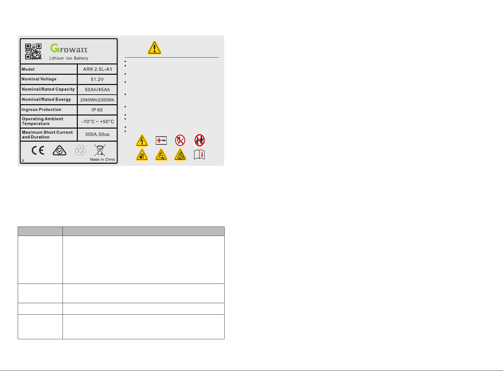
Do not disassemble or alter the PACK to avoid heat ,explosion or fire.Do not use the PACK beyond specifide conditions.It might cause heat generation,damage,or deterioration of its performance.Do not throw,drop,hit,drive a nail in,stamp on the PACK.It may cause heat generation,explosion,or fire.In case of electrolyte leakage,keep leaked electrolyte away from contact with eyes or skin.immediately clean with water and seek helpfrom a doctor.Do not put the PACK into a fire.Do not use it or leave it on a place near fire,heaters,or high temperature sources.It may cause over temperature,explosion or fire.Do not submerge the PACK in water,or wet the product.It may cause heat generation,explosion ,or fire.Do not reversely connect the PACK positive(+)and negative(-)terminal.Do not short circuit by letting the PACK terminals(+and -)contact a wire or any metal.The unit is heavy enough to cause severe injury.Keep out of reach of children or animals.WARNINGX
Fig 2.1: Nameplate Fig 2.2: LabelNote: When the ambient temperature is between -10 ℃ and 0℃, the maximum charging current of the battery is 2.5A.2.4 Emergency ResponsesManufacturer takes foreseeable risk scenarios into consideration and is designed to reduce hazards and dangers. However, if the following situation occurs, do as below:
Situation Occurs
Description and action need
Leakage
Avoid touch of leaking liquid or gas. If you touch the leaking electrolyte, do as below immediately.Inhalation: Evacuate the contaminated area, and seek medical help.Eye contact: Rinse eyes with flowing water for 15 minutes, and seek medical help.Skin contact: Rinse contacted area thoroughly with soap and water, and seek medical help.Ingestion: Vomiting, and seek medical help.
Fire
It's hard for PACK systems ignite spontaneously. If the PACK has caught a fire, do not try to extinguish the fire but evacuate people immediately.
Wet Packs
If PACK is flooded or submerged, do not access it. Contact Growatt or distributor for technical assistance immediately.
Damaged PACKS
Damaged PACKS are dangerous and must be handled with special attention. They are no longer suitable for use and may cause danger to people. If the PACK damaged, stop use it and then contact the Growatt or distributor.
Storage and Transportation 33.1 Storage RequirementsØPlace the PACK follow the identification on the packing case during storage.ØDo not put the PACK upside down or sidelong. ØThe defective PACK needs to be separated from other PACKs. ØThe storage environment requirements are as follows: Install the PACK in a dry and clean place with proper ventilation.The storage temperature for a short week is between -30°C to 60℃.If you store the PACK over a long period of six months, the storage temperature is between-20°C to 50°C, relative humidity: 5%~95%RH. Place the PACK away from corrosive and organic substances (including gas exposure). Free from direct exposure to sunlight and rain .At least two meters away from heat sources (such as a radiator). Free from exposure to intensive infrared radiation. Note: If a PACK is useless for six months, it needs to be recharged.3.2 Transportation RequirementPACK has been certified in UN38.3 (Section 38.3 of the sixth Revised Edition of the Recommendations on the Transport of Dangerous Goods: Manual of Tests and Criteria) and SN/T 0370.2-2009 (Part 2: Performance Test of the Rules for the Inspection of Packaging for Exporting Dangerous Goods). PACK is classified as category 9 dangerous goods.ØThe PACK shall not be transported with other inflammable, explosive or toxic substances.ØEnsure the original Package and label complete and recognizable.ØProhibit direct exposure to sunlight, rain, condensing water caused by temperature difference and mechanical damages.ØProhibit to pile up more than six PACKs.ØThere will be a drop in capacity during transportation and storage.Ø Transportation temperature is between-20°C to 50°C, relative humidity: 5%~95%RH.Recharge procedures 1.Identify the PACK that needs recharging;2.Refer to quick installation guidance, complete the installation and wire connection. Ensure PACK in off status during all the steps.3.Set the power system as “CC=25A, CV=55.8V” , activate the PACK and start recharging.4.Recharge until LED2 flicks.5.Having completed recharge, leave circuit open for five minutes before check voltage. If voltage is not less than 52V, the recharge is successful.
78 4InstallationWARNING
ØEnsure to read the Guidance before installation in order to understand product information and safety cautions;ØOperators should be well trained technicians and fully understand the whole photovoltaic system, grid network, working principle and national regional standards;ØInstallers must use insulating tools and wear safety equipment;ØDevice damages caused by failure to comply with storage, transportation, installation and use requirements specified in Guidance are not coved by Warranty.
4.1 Installation environmentThe ambient temperature for the installation of the battery system shall be above -10℃, below 50℃, and the humidity shall between 5% and 95%.Max.+50℃Min.-10℃RH.+5%~+95%Fig 4.1: Installation environment requirements4.2 Basic installation requirementsØThe PACK can be installed indoors or outdoors. The following conditions are allowed:Fig 4.2: Acceptable wall mounted installationGroundGroundGroundWallFig 4.3: Acceptable floor standing installation
Do not place the PACK upside down.
WARNINGØBuild sun& rain shade to avoid direct exposure to the sunlight and rain.WallWallFig 4.4: Shade for ARK 2.5L-A14.3 Installation Required ToolsThe following tools are required to install the PACK:DrillScrew DriverWrenchPencilTap MeasureMultimeter
1094.4 Installation ProceduresIt is recommended to wear the following safety gear when dealing with the PACK.
Insulated GloveSafety GoggleSafety Shoes
Pre-installation Check
Check the package
Check the PACK package before open it. If any abnormity is detected, do not open the Package and contact your distributor.
Check the power
Check and confirm the PACK is powered off before installation.
Check deliverable
Check the quantity of all parts inside according to the package list. If there is any part missing or damaged, please contact your distributor.
Check the ARK-2.5L-A1Fig 4.5: components and parts of ARK 2.5L-A1Check the accessoriesARK 2.5L-A1ARK 2.5L-A1 CableARK 2.5L-A1 Parallel Cable ARK 2.5L-A1 Base ABCD
Installation Method
Compound Mode
Standard Wall-Mounted Installation
A+B
Standard floor installation
A+B+D
Wall-Mounted Battery system stacked in two line
A+B+C
Floor installation battery system stacked in two line
A+B+C+D*2
Fig 4.6:Multiple ARK2.5L-A1 installation processWall Mounted InstallationStep 1: Please make sure that the weight capacity of wall should exceed 150kg.Step 2: Assemble the wall hangers together. If you want to install four packs, make four wall hangers together. We can parallel two to ten at a time .But, it is recommended that no more than four packs be mounted on wall. Step 3: Place the wall hangers on the wall and mark the holes that need to be punched. We recommend two persons participate the installation. One person places the wall hangers on wall and ensure the gradienter horizontal; the other person marks the holes. Each wall hanger has two fixed positions. After mark the holes, put down the wall hangers.Step 4: Drill a hole at the marked point with a depth of 55mm at the mark with a drill ofφ8.Expand the bolt with a hammer into the hole in the wall , install the nut(including elastic flat pad)and tighten the nut with a wrench.Step 5: Hang the ARK2.5L-A1 on the wall hangers. Adjust the battery level with M6 external hexagon torque wrench and install the safety screws (M4x10 Combination screw) on both sides of all modules.Step 6: Plug the connected power lines into PACK terminals (red positive terminal and black negative terminal). Plug the well-connected CAN communication line into the communication ports of PCS and PACK. Note: The number of wall-mount installations should not exceed four.Floor Standing InstallationFig 4.7:Multiple ARK 2.5L-A1 with base installation process
1112Step 1: Assemble the wall hangers together. If you want to install four packs, make four wall hangers together. We can parallel two to ten at a time . We recommend that the stack number be no higher than six. However, if necessary our structure allows us to stack higher.Step 2: Place the mount base where you want the PACK to be mounted. Put the wall hangers on the wall and match the baseStep 3:Mark the holes that need to be punched. We recommend two persons participate the installation.One person places the wall hangers on wall and ensure the gradienter horizontal; the other person marks the holes. Noted that only two ends of the top wall hanger and the bottom wall hanger need to be marked.. After mark the holes, put down the wall hangers.Step 4: Drill a hole at the marked point with a depth of 55mm at the mark with a drill of φ8. Expand the bolt with a hammer into the hole in the wall , install the nut(including elastic flat pad)and tighten the nut with a wrench.Step 5: Hang the ARK2.5L-A1 on the wall hangers. Adjust the battery level with M6 external hexagon torque wrench and install the safety screws (M4x10 Combination screw) on both sides of all modules.Step 6: Plug the connected power lines into PACK terminals (red positive terminal and black negative terminal). Plug the well-connected CAN communication line into the communication ports of PCS and PACK.Note:If more than 4 batteries are used, base mounting is recommended.For floor installation, we recommend that the number of the stacked battery modules is no higher than six.4.4 Electrical Connection
Do not forget wear ESD wrist strap and gloves, safety gloves and goggles.
WARNINGTerminal Definition:Fig 4.8: Terminal Definition
Serial number
Item
Quantity
Specifications
Symbol
1
Communication Port
1
IP67 RJ45water proof connector
PCS
2
Communication Port
1
IP67 RJ45water proof connector
LINK-IN
3
Communication Port
1
IP67 RJ45water proof connector
LINK-OUT
4
Safety vent
1
Pressures inside released via the vent.
PCS
5
Negative terminal
2
IP67 –Black connector
BAT-
6
Grounding terminal
2
M6 Screw
7
Positive terminal
2
IP67–Red connector
BAT+
8
USB interface
1
USB interface for Program Upgrade
BAT-
9
LED
1
Five leds
BAT+
10
POWER button
1
IP67—Button to turn on or off the PACK
POWER
RS485&CAN crystal plug definition:
Item
Crystal head picture
Serial no.
Definition
PCS
1
RS485_B
2
RS 485_A
3
GND_COM
4
CANH
5
CANL
6
GND_COM
7
WAKE-
8
WAKE+
Communication interface definition:
1413Fig 4.9: System connection diagram Fig 4.10: parallel connection stacked in two lineNote:The battery is not allowed to be installed in the running state, and all the RUN lights of battery modules should be off before installation.To ensure system security, do not forget to install ground wire.For the power lines connected to PCS, the positive power line is drawn from the top battery module, and the negative power line is drawn from the bottom battery module .The breaker between PCS and ARK, we recommend to use molded case circuit breaker with rated working voltage greater than 500V and rated working current greater than 125A.4.4.2 System connection diagram of two line4.4.1 System connection diagram When stacked in two lines, you need to buy the accessory of wires connecting two stacks of battery systems. The connection mode is shown in the figure 13.4.4.3 Electrical wiring connection1. When the power wiring harness is connected, please pay attention to the positive and negative terminals, the red terminals are connected to the positive terminals and the black terminals to the negative terminals.2. The PCS communication terminal is used to communicate to the PCS. Link-in terminals are used for signal inlet of multiple parallel battery packs. Link-out terminals are used for signal output of multiple parallel battery packs.4.4.4 Power line connectionPress the position indicated in the figure above before disconnecting the power terminal.Fig 4.11: Connect and disconnect power terminals4.4.5 Communication line connectionFig 4.12: Connect and disconnect communication terminals1.Parallel communication is the connection between the middle communication plug of the first module and the lower communication plug of the next module.2.The uppermost communication plug of the top battery module is connected to the PCS.
1516 5Power on and off the Battery5.1 Power On
Power on the PACK by pressing power button(t>2S)
Serial
Procedures
Acceptation criteria
1
Connect the battery and PCS
Make sure the wiring harnesses are well connected
2
Close the breaker of the PACK
Make sure the breaker is ON
3
Press POWER button for three to eight seconds. Observe the LED indication on panel.
1. If both RUN/ALM and SOC lights turn on normally, PACK is powered on successfully.2. If RUN/ALM light turns red, there is a failure and should solve it before power on again.
Power on the PACK by PCS
1
Connect the battery and PCS
Make sure the wiring harnesses are well connected
2
Close the breaker of the PACK
Make sure the breaker is ON
3
Power on the PCS. PCS outputs a wake up signal of 5V or an output main circuit voltage signal of 46-58V
1. If both RUN/ALM and SOC lights turn on normal, PACK powers on successfully.2. If RUN/ALM light turns red, there is a failure and should solve it before power on again.
5.2 Power offPress the power button to turn off the PACK and five LED lights will flicker for three times. If under the situation of multiple packs in parallel, only turning off one of the packs then the whole battery system will turn off.Maintenance Guide 66.1 PreparationØTools like safety gloves, cross head driver and socket wrench should be prepared.ØTurn off and turn on new PACK.1. If the PACK is power-off. Press power button for 3-8 seconds to turn on.2. If the PACK is power-on. Press power button once to turn off.Before maintaining the battery, turn off the breaker and press power button once to make sure the PACK is in the power-off mode. Follow the installation and wire connection procedures specified above. Ensure wires are properly connected before turn the breaker on. After that, turn on the breaker and press power button of any PACK for 3-8 seconds to check if the system normal works.6.2 PACK Replacement§Wear safety gloves.§Close the breaker and power off the PACK.§Disconnect power lines and CAN communication lines of the PACK.§Wall-mounting PACK: Uninstall the safety screws on both sides of the PACK. Lift up the PACK.§ Floor-standing PACK: Uninstall the safety part and open the connector at both ends of the battery of the batteries. Lift up the PACK.§Put the PACK into the packing box according to the repair procedure and transport the PACK to the designated repair site.§Install new PACK based on procedure specified in Section 4. WARNING
ØThe installation and use of batteries involve much specialized knowledge. Therefore, technicians should be given appropriate technical training and obtain operational certificates in compliance with local laws and regulations. Please ensure technicians have obtained training certificate before operation.ØPlease stand on dry insulating objects and do not wear conductive material such as watches and necklace during operation. Insulated tools should be used.ØDo not contact any positions with potential difference.ØProhibition sign should be hung on the battery: " Non - professionals, do not touch.ØIf any abnormalities occur during the startup phase, power off the PACK immediately. After problem confirmed, proceed again.ØMake sure the inverter is turned off before checking the PACK.
6.3 System Failure Information List and Troubleshooting Suggestions
Error Indication
Error description
Error cause
Suggested actions
ALM
( ALM Light Flickers)
Discharge under voltage protection
Single cell voltage below the threshold for under-voltage protection.
There is over discharge risk. User should stop discharging and arrange recharge
Charge over voltage protection
Single cell voltage exceedingthreshold for protectionthreshold.
1. There is no safety threat;2. User should stop charging. IdlePACK and it will turn to normal status.
External CAN Communication failure
Communication loss betweenPCS and PACK.
1. There is no safety threat and user should stop using battery.2. Check if PCS and battery communicationterminal is well connected.3. If PCS and PACK cannot communicate when thecommunication wire is confirmed well connected, user should contact installer to repair battery.
1718
Interior CAN Communication failure
Communication loss betweentwo parallel
1. Check Can connection betweentwo batteries, CAN connectionbetween Linkin and Linkout;
Parallel connection failureprotection
Communication failure between two parallel connected PACK
1. Check Can connection between two batteries, CAN connection between Battery and PCS;
(ALM Light on)
Discharge short circuit
External short circuit of PACK
There is safety risk and user should stop using batteryUser should contact installer to repair PCS and battery
Precharger short circuit
Precharger overtime circuit
Type inconsistency of PACK
The pack type is different
There is safety risk and user should stop using batteryUser should contact installer to use the same PACK in Parallel.
Main circuit fault
BMS main power circuit failure
There is safety risk and user should stop using battery.User should contact installer to repair battery
Technical Specifications7 Functional parameters of ARK 2.5L-A1 Energy Storage System are as shown below:
No.
Items
Specification
1
Battery Module
ARK 2.5L-A1 (2.56kWh, 51.2V, 27kg)
2
Nominal Capacity/Energy
50Ah/2.56kWh
3
Rated/Usable Capacity/Energy
45Ah/2.3 kWh
4
Typical Voltage
51.2V
5
Operating Voltage
47.2 - 56.8V
6
Standard charging current(25℃)
25A
7
Battery Type
Cobalt Free Lithium Iron Phosphate (LFP)
8
Operative temperature range
-10~50℃
9
Recommended operating temperature
0℃~30℃
10
Storage conditions
Temperature: -10°C ~ + 50°CHumidity:5%~95%RHWithin six months after initial charge
11
Cooling
Natural cooling
12
Dimension (W/D/H)
650/260/185mm
13
Weight
27kg
14
Installation
Wall-mounted installation/floor standing installation
15
Ingress protection
IP65
16
Cell safety certification
IEC62619/UL1642
17
PACK safety certification
IEC62619/CE/RCM/ CEC
18
UN transportation test standard
UN38.3
19
Communication port
CAN/RS485
20
Parallel connection
Two-Ten PACKs
21
Maximum current for multiple parallel machines to PCS
100A
2019Appendix ILED indication Control Mechanism
LED light definition
Status
Items
SOC indication
RUN/ALM
Remark
LED1
LED2
LED3
LED4
LED5
Charge SOC
0%-25%
(t=1S)
RUN/ALM light on and one SOC lights flicker
26%-50%
(t=1S)
51%-75%
(t=1S)
76%-99%
(t=1S)
100%
Discharge SOC
100%-76%
75%-51%
50%-26%
25%-5%
5%-0%
(t=1S)
RUN/ALM light flicker
Idle
100%-76%
75%-51%
50%-26%
25%-5%
5%-0%
(t=1S)
RUN/ALM light flicker
Over charge and over discharge protection
(t=1S)
RUN/ALM light flicker green
Charging current limit does not respond
(t=1S)
RUN/ALM light flicker green
Charge and discharge high temperature alarm
(t=1S)
RUN/ALM light flicker green
Charge and discharge high temperature protection
(t=1S)
RUN/ALM light flicker green
Charge and discharge low temperature alarm
(t=1S)
RUN/ALM light flicker green
Charge and discharge low temperature protection
(t=1S)
RUN/ALM light flicker green
Cell discharge undervoltage alarm
(t=1S)
RUN/ALM light flicker green
Cell discharge undervoltage protection
(t=1S)
RUN/ALM light flicker green
PACK discharge undervoltage alarm
(t=1S)
RUN/ALM light flicker green
PACK discharge undervoltage protection
(t=1S)
RUN/ALM light flicker green
Charge and discharge Overcurrent hardware protection
(t=1S)
RUN/ALM light flicker green
Parallel connection
Parallel connection succeeds
RUN/ALM light flicker green
Protection
Cell charge overvoltage alarm
LED1-LED4 indicates current remaining capacity
(t=1S)
RUN/ALM light flicker green
Cell charge overvoltage protection
(t=1S)
RUN/ALM light flicker green
PACK charge overvoltage alarm
(t=1S)
RUN/ALM light flicker green
PACK charge overvoltage protection
(t=1S)
RUN/ALM light flicker green
Over charge and over discharge alarm
(t=1S)
RUN/ALM light flicker green
2221
Mos high temperature alarm
(t=1S)
RUN/ALM light flicker green
Mos high temperature protection
(t=1S)
RUN/ALM light flicker green
High temperature environment alarm
(t=1S)
RUN/ALM light flicker green
High temperature environment protection
(t=1S)
RUN/ALM light flicker green
Cell Large voltage difference alarm
(t=1S)
RUN/ALM light flicker green
Cell Large voltage difference protection
(t=1S)
RUN/ALM light flicker green
difference protection between PACK voltage and module voltage
(t=1S)
RUN/ALM light flicker green
Parallel connection over charge and over discharge alarm
(t=1S)
RUN/ALM light flicker green
Fault,personnel handling required
Discharge short circuit
LED1-LED4 indicates current remaining capacity
(t=1S)
RUN/ALM light flicker red
Precharged short circuit
(t=1S)
RUN/ALM light flicker red
Precharged overtime circuit
(t=1S)
RUN/ALM light flicker red
External CAN communication failure
(t=1S)
RUN/ALM light flicker red
Interior CAN communication failure
(t=1S)
RUN/ALM light flicker red
Parallel connection failure
(t=1S)
RUN/ALM light flicker red
Type inconsistency of PACK
(t=1S)
RUN/ALM light flicker red
Batteries failure protection
RUN/ALM light stays red
Voltage sampling anomaly protection
RUN/ALM light stays red
Current sampling fault
RUN/ALM light stays red
Main circuit fault
RUN/ALM light stays red
IFpP/39.5/148/95/[16S]M/-10+50/90Method for calculating rated capacity:Rated capacity of the measured module: 45 AhNumber of modules connected in parallel: 10Calculated rated capacity (Ah) = 45 Ah×N = 45*N Ah (N=1~10)Recommend charging method declared by the manufacturer:1.Constant current 25A charging to 54V;2.Constant current 10A charging to 55V;3.Constant current 2A charging to 55V;

This manual suits for next models

1

Other Growatt Storage manuals

Growatt AXE 5.0L-C1 User manual

Growatt

Growatt AXE 5.0L-C1 User manual

Growatt ARK 5.12~25.6XH-A1 Operating and maintenance instructions

Growatt

Growatt ARK 5.12~25.6XH-A1 Operating and maintenance instructions

Growatt Future-H Series User manual

Growatt

Growatt Future-H Series User manual

Growatt ML33RTA User manual

Growatt

Growatt ML33RTA User manual

Popular Storage manuals by other brands

strada Aquatherm STA140UC Technical manual

strada

strada Aquatherm STA140UC Technical manual

Buffalo HD-GDU3 user manual

Buffalo

Buffalo HD-GDU3 user manual

Microdia MMCmicro operating manual

Microdia

Microdia MMCmicro operating manual

Costway BA7880 manual

Costway

Costway BA7880 manual

Dell PowerVault 725N Firmware update

Dell

Dell PowerVault 725N Firmware update

weha Hippo Bundle Rack Set Operation and service instructions

weha

weha Hippo Bundle Rack Set Operation and service instructions

Metalware WIDESPAN Assembly instructions

Metalware

Metalware WIDESPAN Assembly instructions

Fantec MD-26U3 500GB specification

Fantec

Fantec MD-26U3 500GB specification

HP StorageWorks DAT 40i Getting started guide

HP

HP StorageWorks DAT 40i Getting started guide

Seagate Barracuda 7200.14 product manual

Seagate

Seagate Barracuda 7200.14 product manual

HP StorageWorks 8B - FC Entry Switch manual

HP

HP StorageWorks 8B - FC Entry Switch manual

Fujitsu MHW2040BS product manual

Fujitsu

Fujitsu MHW2040BS product manual

Silicon Graphics Total Performance 9300 user guide

Silicon Graphics

Silicon Graphics Total Performance 9300 user guide

Seagate Barracuda ST310215A installation guide

Seagate

Seagate Barracuda ST310215A installation guide

SmartDisk FireLite Specifications

SmartDisk

SmartDisk FireLite Specifications

Western Digital Computer Hard Drive installation guide

Western Digital

Western Digital Computer Hard Drive installation guide

Rackable Systems OmniStor 4700S Series user guide

Rackable Systems

Rackable Systems OmniStor 4700S Series user guide

Transcend StoreJet 2.5 SATA Series user manual

Transcend

Transcend StoreJet 2.5 SATA Series user manual

manuals.online logo
manuals.online logoBrands
  • About & Mission
  • Contact us
  • Privacy Policy
  • Terms and Conditions

Copyright 2025 Manuals.Online. All Rights Reserved.