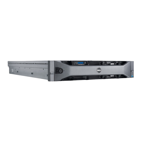
StorageWorks RW551 User manual

Medium Optical Disk Library
(RW551/RW552)
Service Manual
EK–MOL80–SV. B01
Digital Equipment Corporation
Maynard, Massachusetts

Second Edition, November, 1997
The information in this document is subject to change without notice and should
not be construed as a commitment by Digital Equipment Corporation.
Digital Equipment Corporation assumes no responsibility for any errors that
might appear in this document.
The software described in this document is furnished under a license and may be
used or copied only in accordance with the terms of such license. No
responsibility is assumed for the use or reliability of software or equipment that
is not supplied by Digital Equipment Corporation or its affiliated companies.
The following are trademarks of Digital Equipment Corporation: the DIGITAL
logo and StorageWorks.
The following are third-party trademarks:
Microsoft and MS-DOS are registered trademarks of Microsoft Corporation.
Copyright © 1997 Digital Equipment Corporation. All rights reserved
Reproduced with permission of the Hewlett-Packard Company Printed in U.S.A.

EK–MOL80–SV. B01 iii
Contents
1 Product Information
Product Features ................................................................................................1–1
The Optical Drive Mechanism ...........................................................................1–3
Product Support .................................................................................................1–4
Product Matrix ...................................................................................................1–4
Characteristics ...................................................................................................1–4
2 Environmental/Installation/PM
Environmental Requirements .............................................................................2–1
Primary Power/External Ground ........................................................................2–1
Clearance Requirements ....................................................................................2–1
Location Requirements ......................................................................................2–2
Responsibilities ..................................................................................................2–2
Checkout Procedure .........................................................................2–2
Unpacking & Taking the Jukebox Off the Pallet...............................2–3
Tools Required.................................................................................2–3
3 Product Configuration and Operation
Connections to the RW551/RW552 Jukebox ......................................................3–1
Configuring and Operating the Jukebox..............................................................3–3
Connecting an Uninterruptable Power Supply (UPS) ..........................................3–3
Connecting the SCSI Cable to the Jukebox.................................................3–4
Connecting Power.......................................................................................3–5
Control Panel Operation......................................................................................3–6
Using Selection Buttons..............................................................................3–7
Understanding Display Window Messages..................................................3–7
Viewing and/or Setting SCSI Ids and Logical Unit Numbers (LUNs) ........3–8
Changing an Optical Drive SCSI Address.................................................3–13
Changing a Configuration Option.............................................................3–14
Loading an Optical Disk into the Jukebox.................................................3–17
Ejecting an Optical Disk from the Jukebox...............................................3–19
Setting a Security Code ............................................................................3–20
Moving or Shipping the Jukebox.......................................................................3–21

Medium Optical Disk (RW551/RW552) Library
iv EK–MOL80–SV. B01
3 Product Configuration and Operation (continued)
Moving the Jukebox a Short Distance ..............................................................3–22
Shipping the Jukebox ..................................................................... 3–23
Host Configuration........................................................................................... 3–23
4 Troubleshooting and Diagnostics
Operation / Installation Troubleshooting ............................................................4–1
Troubleshooting Using the Control Panel and Observation ........................4–1
The Autochanger Lists the First "Possibles" ..............................................4–2
Evaluating Results of the Internal FRU Isolation .......................................4–2
Retrieving Performance Information .........................................................4–3
Getting Error Information through the SCSI Bus .......................................4–6
Diagnostics ................................................................................................4–7
Offline Diagnostics ....................................................................................4–8
Recovery from Hardware Errors............................................................... 4–14
Running an Internal Test.......................................................................... 4–34
Optical Disk Cleaning ...................................................................................... 4–38
Using the Eject Tool to Remove a Disk from the Drive....................................4–40
5 Removal and Replacement
Field–Replaceable Assemblies ..........................................................................5–2
ESD Precautions ................................................................................................5–2
Tools Required ..................................................................................................5–2
Disassembly/Reassembly Procedures (SCSI–Connect Version) ..........................5–3
Service Access ..........................................................................................5–4
Right and Left Lower Access Panels .........................................................5–4
Rear Access Panel .....................................................................................5–5
Front Left and Front Right Panels .............................................................5–6
Replacing the Power Supplies .................................................................5–11
Replacing the Mailslot Assembly............................................................. 5–12
Replacing the Control Panel Assembly ...................................................5–13
Replacing an Optical Drive ..................................................................... 5–14
Replacing the Interposer PCA .................................................................5–16
Replacing a Cooling Fan .........................................................................5–16
Replacing the Picker ...............................................................................5–17
Removing/Replacing the Translate Frame ............................................... 5–21
Removing/Replacing the Encoder Strip ...................................................5–27
Replacing the Vertical Motion Motor ...................................................... 5–28
Replacing the Vertical Motor Gear Box...................................................5–30

Contents
EK–MOL80–SV. B01 v
5 Removal and Replacement (continued)
Replacing the Controller PCA....................................................................5–35
.......................................................Replacing the Internal SCSI Cable
5
Replacing the SCSI Interface PCA.............................................................5–38
Re–initializing the Jukebox Controller PCA RAM After Service ...............5–40
Field Replaceable Units (FRUs) in the Medium Library.............................5–42
Recommended Service Kits .......................................................................5–44
Miscellaneous............................................................................................5–52
6 Theory of Operation
Autochanger Robotics.........................................................................................6–2
Movements.......................................................................................6–2
The Autochanger Controller PCA .................................................................6–4
Interposer PCA..............................................................................................6–6
Power Supplies .............................................................................................6–7
SCSI Repeater/Converter/LUN PCA .............................................................6–7
Picker .........................................................................................................6–10
Single–Picker Mode ................................................................................6–10
Dual–Picker Mode ...................................................................................6–10
Two–Move Exchange ..............................................................................6–10
Dual–Picker Exchange .............................................................................6–11
Quick Exchange.......................................................................................6–12
The Multi–function Optical Drive & Drive Controller......................................6–13
Controller PCA ........................................................................................6–14
SCSI Controller........................................................................................6–14
Data Buffer ..............................................................................................6–14
Formatter/Sequencer ................................................................................6–14
Servo PCA ...............................................................................................6–14
DSP Microprocessor and Support/Servo Control Loops............................6–14
Read and Write Channel Electronics........................................................6–15
Mechanism Assembly....................................................................................6–15
Loader Mechanism...................................................................................6–15
Optical Head............................................................................................6–15
Optical Disk Layout and Error Correction.........................................................6–16
Disk Formats............................................................................................6–16
Controller.................................................................................................6–17
CPU.........................................................................................................6–17
Gate Array ...............................................................................................6–17

Medium Optical Disk (RW551/RW552) Library
vi EK–MOL80–SV. B01
6 Theory of Operation (continued)
DSP (Digital Signal Processor)....................................................................... 6–17
Read/Write Channel Electronics ..............................................................6–17
Loading Motor.........................................................................................6–18
Bias Magnet.............................................................................................6–18
Optical Head............................................................................................ 6–18
Optical Disk Layout and Error Correction......................................................6–18
Disk Formats............................................................................................6–18
Optical Disk Layout................................................................................. 6–19
User Zone Layout ....................................................................................6–19
650–Mbyte Disk and Spare Groups..........................................................6–20
1.3–Gbyte Disk User and Spare Groups ................................................... 6–20
2.6 Gbyte Disk User and Spare Groups .................................................... 6–20
Drive Defect Management................................................................................ 6–32
Slip Sparing Algorithm..................................................................................... 6–33
Replacement Sparing Algorithm.......................................................................6–34
Error Thresholds...............................................................................................6–34
Diagnostic Strategy .......................................................................................... 6–35
Internal Autochanger Diagnostics ............................................................ 6–35
The SCSI Interface...................................................................................6–35
Single–Ended and Differential SCSI Interfaces ........................................6–36
SCSI Command Set.......................................................................................... 6–37
Appendix A Basic Supplies and Reorderable Parts
Basic Supplies & Reorderable Parts................................................................... A–1
Related Documents............................................................................................ A–2
Figures
1–1 RW551 & RW552 Jukebox......................................................................1–1
2–1 Clearance Requirements...........................................................................2–1
2–2 Installing the Ramp Onto the Pallet..........................................................2–3
3–1 Front Panel ..............................................................................................3–1
3–2 Rear Panel (SCSI Connect) .....................................................................3–2
3–3 The Jukebox Control Panel.......................................................................3–6
3–4 Control Panel Menu Tree .........................................................................3–9
4–1 The Autochanger Returns Suspect FRUs .................................................4–2
4–2 How Service Views the Suspect FRUs ....................................................4–3
4–3 Information and Tests Through the SCSI Bus ..........................................4–7
5–1 Right Lower Access Panel .......................................................................5–4

Contents
EK–MOL80–SV. B01 vii
Figures (continued)
5–2 Rear Access Panel ...................................................................................5–5
5–3 Center Cover Mounting Screw .................................................................5–6
5–4 Positioning the Control Display Before Removing the Panel ...................5–7
5–5 Accessing the Underside of the Control Panel ..........................................5–8
5–6 Disconnecting the Control Panel Cable ....................................................5–9
5–7 Removing the Front Right Panel ..............................................................5–9
5–8 Power Supplies ......................................................................................5–11
5–9 Power Test Points on the Interposer PCA ...............................................5–12
5–10 Accessing the Mailslot Assembly ..........................................................5–12
5–11 Control Panel Mounting Screws .............................................................5–13
5–12 Optical Drives–with Cables Connected ..................................................5–14
5–13 Optical Drives–with Cables Disconnected .............................................5–15
5–14 Optical Drive Mounting .........................................................................5–15
5–15 Interposer PCA ......................................................................................5–16
5–16 Cooling Fan ...........................................................................................5–17
5–17 Picker Umbilical Cable ..........................................................................5–17
5–18 Picker Translate Cable ...........................................................................5–18
5–19 Picker Translate Cable (stowed) ............................................................5–19
5–20 Stopping Vertical Motor Gear Box Motion ............................................5–19
5–21 Picker Capture Bracket Mounting ..........................................................5–20
5–22 Picker Capture Bracket ..........................................................................5–20
5–23 Rotating the Picker Assembly Out of the Translate Frame .....................5–21
5–24 Translate Frame Raised For Easier Access .............................................5–22
5–25 Stopping Vertical Motor Gear Box Motion ...........................................5–23
5–26 Encoder Strip Mounting Peg ..................................................................5–24
5–27 Picker Translate Frame Tensioners ........................................................5–25
5–28 Translate Frame Rear Tensioner Mount .................................................5–25
5–29 Translate Frame Tensioners Released ....................................................5–26
5–30 Retaining Peg On Lower End of the Encoder Strip.................................5–27
5–31 Encoder Strip Mounting Screw...............................................................5–28
5–32 Top Mount Of Encoder Strip ..................................................................5–28
5–33 Vertical Motion Motor............................................................................5–29
5–34 Slave Rope Tensioner Assembly.............................................................5–30
5–35 Pivoting the Tensioner Lever to Release Tension ...................................5–31
5–36 Taking the Drive Rope Off the Top Pulleys............................................5–32

Medium Optical Disk (RW551/RW552) Library
viii EK–MOL80–SV. B01
Figures (continued)
5–37 Disconnecting the Drive Rope From a Tensioner ................................... 5–32
5–38 Two Ends of the Slave Rope In the Tensioner........................................ 5–33
5–39 Disconnecting the 3–Rope Coupler ........................................................5–33
5–40 Rear Side Of Vertical Motor Gear Box...................................................5–34
5–41 The Rope and Pulley System..................................................................5–34
5–42 Positioning the Tensioner to Mount On Translate Frame........................ 5–35
5–43 Controller PCA–Cover On ..................................................................... 5–36
5–44 Controller PCA–Cover Off.....................................................................5–36
5–45 Controller PCA–Cables Off.................................................................... 5–37
5–46 Interface/Power Distribution Assembly..................................................5–38
5–47 SCSI Converter/Repeater PCA; Power Distribution PCA(Below)...........5–38
5–48 SCSI PCA Jumpers ................................................................................5–39
5–49 Jukebox Exploded View.........................................................................5–47
5–50 Jukebox Power Harness..........................................................................5–49
5–51 Jukebox Pulley and Rope Diagram.........................................................5–50
6–1 SCSI Command Translation for Autochanger Operation ..........................6–2
6–2 Autochanger Controller PCA Block Diagram ..........................................6–4
6–3 Interposer PCA ........................................................................................6–6
6–4 Power Supplies and Power–on Sequence .................................................6–7
6–5 SCSI Repeater/Converter/LUN PCA .......................................................6–8
6–6 Functional Diagram ............................................................................... 6–13
6–7 4X–Drive Functional Diagram ..............................................................6–16
6–8 Optical Disk Layout............................................................................... 6–19
6–9 User Zone Layout for 650–Mbyte Media ............................................... 6–21
6–10 User Zone Layout for 1.3–GByte Media, g=1.........................................6–22
6–11 User Zone Layout for 1.3–GByte, g=16 ................................................. 6–23
6–12 User Zone Layout for 2.6–Gbyte Media, 1,024 bytes/sector...................6–24
6–13 User Zone Layout for 2.6–Gbyte Media, 512 bytes/sector......................6–25

Contents
EK–MOL80–SV. B01 ix
Tables
1–1 Optical Disk Standards Met by Digital Optical Disks .................................1–3
1–2 Jukebox Capacities ....................................................................................1–3
1–3 RW551/RW552 Jukebox Matrix ................................................................1–4
3–1 UPS Power Requirements...........................................................................3–4
3–2 SCSI Cable Length Limitations..................................................................3–5
3–3 Default SCSI and LUN Settings................................................................3–11
3–4 Default LUN Settings/LUN Settings if “DRVs ID” Address is Changed...3–11
3–5 Configuration Choices..............................................................................3–15
4–1 Information Logs .......................................................................................4–4
4–2 Operation Errors.........................................................................................4–9
4–3 Hardware Errors and Recovery Procedures ..............................................4–14
4–4 Micro–Move IDs .....................................................................................4–25
4–5 Available Internal Tests for the RW551 and RW552 ...............................4–34
5–1 List of Field Replaceable Units.................................................................5–42
5–2 Exchange Parts.........................................................................................5–44
5–3 Non-Exchange Parts .................................................................................5–45
5–4 Common Resource Parts...........................................................................5–52
6–1 Values for n and m for 1.3 Gbyte with g=16 (1,024 media) ......................6–26
6–2 Physical Revolution to Logical Track Layout...........................................6–27
6–3 4X, 1,024 Bytes/Sector Disk Structure......................................................6–28
6–4 4X, 512 Bytes/Sector Disk Structure.........................................................6–29
6–5 Technical Comparisons of 1X, 2X, and 4X Optical Drives .......................6–31
6–6 Error Thresholds ......................................................................................6–35
A–1 Common Resource Parts............................................................................A–1
A–2 Related Documentation .............................................................................A–2
A–3 TIMA Documents......................................................................................A–3

EK–MOL80–SV. B01 xi
Revision Record
This Revision Record provides a concise publication history of this guide. It lists the
guide revision levels, release dates, and reasons for the revisions. It also describes how
the changes to affected pages are marked in the guide.
Revision Level Date Summary of Changes
EK–MOL80–SV. A01 December, 1996 First Edition
EK–MOL80–SV. B01 November, 1997 Corrects table 5–1; adds
table and exploded view
of non-exchange parts.

EK–MOL80–SV. B01 xiii
About This Manual
This manual describes how to install, configure, and maintain medium optical disk library
RW551/RW552. The manual also discusses the theory of operation of the library.
Audience
This manual supports trained service personnel for the medium optical disk
library (also referred to as the “jukebox”) RW551/RW552.
Document Organization
This manual contains the following:
Chapter 1: Product Information
Provides general product information and lists important features and
specifications.
Chapter 2: Environmental/Installation/PM
Describes disk jukebox environmental requirements and installation procedures.
Chapter 3: Product Configuration and Operation
Provides information about the operational control on the jukebox and how to
use those controls to configure and operate the jukebox.
Chapter 4: Troubleshooting and Diagnostics
Contains troubleshooting information about the SCSI-connect.
Chapter 5: Removal and Replacement
Describes how to locate and replace sub-assemblies within the RW551/RW552
enclosure. It also contains a list of Field Replaceable Units (FRUs) and an
exchange and non-exchange parts list with an accompanying exploded view of
the library.

Medium Optical Disk (RW551/RW552) Library
xiv EK–MOL80–SV. B01
Chapter 6: Theory of Operation
Describes how the RW551/RW552 works and the relationship between the
mechanical operation and command set execution.
Appendix A: Basic Supplies and Re-orderable Parts
A listing of common parts and other optical disk library manuals which may be
beneficial to the reader.
Typographical Conventions
The following typographical conventions are used in this manual:
Italic Font - Italic font designates the title of a document and statements that
need to be emphasized.
SERIF TYPE – denotes information that is displayed in the display window of
the jukebox.
SAN-SERIF TYPE – indicates the key to press on the jukebox control panel
NOTES, CAUTIONS, and WARNINGS
NOTE
A note calls attention to information which can
be helpful in understanding the operation of
the product.

About This Manual
EK–MOL80–SV. B01 xv
CAUTION
Caution calls attention to an operating
procedure or practice which could result in
damage to the product if not correctly
performed. Do not proceed beyond this
symbol until you fully understand and meet the
indicated conditions.
WARNING
Warning calls attention to a procedure or
practice which could result in personal in-jury
if not correctly performed. Do not proceed
beyond this symbol until you fully understand
and meet the indicated conditions.
Reader Comments
Digital is committed to providing the best products, and we consider our manuals to be
important components of our products. Therefore, you are encouraged to submit your
comments, suggestions, and corrections to help us improve our product documentation.
Please submit all comments and corrections to this manual on the Reader Comment
Form included at the back of this manual.

EK–MOL80–SV. B01 1–1
1
Product Information
This chapter provides general product information and lists important features and speci-
fications. A matrix of environment specifications provide parameters for several sub-
assemblies.
Figure 1–1 RW551/RW552 Jukebox
Product Features
The SCSI-connect version of the RW551, RW552 optical disk jukeboxes have
the following features:
• direct online access to data
• data security through the ability to "lock" the jukebox, preventing disk re-
moval

Medium Optical Disk (RW551/RW552) Library
1–2 EK–MOL80–SV. B01
• SCSI Interface
• single-ended or differential
• SCSI-2 command set
• autochanger reliability of:
• 100,000 hours MTBF (Mean Time Between Failure)
• 1,000,000 MSBF (Mean Swaps Between Failure)
• modular replacement of all major assemblies
• downloadable firmware for the drive mechanism and the autochanger con-
troller PCA
• a digital signal processor (DSP) based servo built into the drive mechanism for
faster seek times and lower error rates
• split optics resulting in the use of a lighter optical head for faster and more ac-
curate data access
• full read and write data caching to optimize system performance
• high reliability and data security when using DEC brand rewritable and write-
once 5.25-inch optical disks
• Digital magneto-optical disks meet the following standards:

Chapter 1. Product Information
EK–MOL80–SV. B01 1–3
Table 1–1 Optical Disk Standards Met by Digital Optical Disks
Type Capacity/Format Standard
Rewritable 594 Mbyte 512 bytes/sector
650 Mbyte
1024 †bytes/sector
Meets ANSI and ISO standards for Con-
tinuous – Composite (CC) format – con-
forms to ISO/IEC DIS 10089A; ANSI S3.21
2-199x
1.2 Gbyte 512 bytes/sector
1.3 Gbyte
1024 †bytes/sector
Meets ECMA 184 standard for Continuous
– Composite (CC) format
Write-Once 594 byte 512 bytes/sector
650 Mbyte
1024 †bytes/sector
Meets ISO and ANSI standards for Con-
tinuous – Composite – Write-Once format
(CCW) – conforms to ISO/IEC DIS 11560;
ANSI X3.220-199x
2X –
1.2 Gbyte 512 bytes/sector
1.3 Gbyte
1024 † bytes/sector
Meets ECMA 184 standard for Continuous -
Composite - Write-Once format (CCW)
4X –
2.3 Gbyte 512 bytes/sector
2.6 Gbyte 1,024 bytes/sector
Meets ISO/IEC 10089A, 11560, and 14517
standards for - Continuous - Composite -
(CC) format
†DIGITAL Operating Systems only support 512 bytes/sector
The Optical Drive Mechanism
The optical drive mechanisms (RWZ53) in the autochanger of the jukebox are
multifunction drives that can operate in both rewritable and write-once modes.
The drives use both rewritable and write-once 5.25-inch magneto-optical disks
that comply with ANSI and ISO standards for Continuous Composite format.
The drives can sense a rewritable or write-once disk by the formatting on the
disk and enter the appropriate mode.
Table 1–2 Jukebox Capacities
Disk Capacity/Format No. of Slots Max. Jukebox Capacity
1.3 GByte, 1,024 bytes/sector 32 41.6 GBytes
1.3 GByte, 1,024 bytes/sector 64 83.2 GBytes
Capacity Upgrade Kit 32 41.6 GBytes
2.6 Gbyte, 1,024 bytes/sector 32 83.2 Gbytes
2.6 Gbyte, 1,024 bytes/sector 64 166.4 Gbytes

Medium Optical Disk (RW551/RW552) Library
1–4 EK–MOL80–SV. B01
Product Support
Host support for the jukebox is continually expanding; therefore, specific host
system support cannot be provided accurately in this manual. However, host
system support is documented in the current Product Service Plan and applicable
Software Product Descriptions (SPD).
Product Matrix
Table 1–3 RW551/RW552 Jukebox Matrix
Product/Option HP Designation Description
RW551-ZC Model 80fx (1150H) Optical jukebox with two
Model OPT 728 multifunction optical drives and
capacity for up to 32 rewritable or
MO-Worm disks. One blank
disk included. Single-ended and
differential SCSI interfaces.
RW552-ZF Model 80Fx (1160H) Optical jukebox with four
Model OPT 728 multifunction optical drives and
capacity for up to 64 rewritable or
MO-Worm disks. One blank disk in
cluded. Single-ended and differential
SCSI.
RW552-UB Adds two multifunction drives &
32 disk slots in 8 magazines.
Characteristics
This section provides the physical characteristics and environmental specifica-
tions for the jukeboxes.
Optical Disk Jukebox/Drive Mechanism
Technical Characteristics (Drive) RWZ53 Drive
Rotational speed 3000 rpm (1X & 2X))
3600 rpm (4X)
Average seek 25.0 ms
Average access time 35 ms (4X disks)
33.3 ms (1X & 2X disks)

Chapter 1. Product Information
EK–MOL80–SV. B01 1–5
Technical Characteristics (Drive) RWZ53 Drive
Read transfer rate - max, sustained - for 1,024 bytes/sector
up to 1.69 Mb/s (4X disks)
up to 1.24 Mb/s (2X Mb disks)
up to 1.04 Mb/s (1X disks)
Write transfer rate- max, sustained - for 1,024 bytes/sector
up to 0.84 Mb/s (4X disks)
up to 0.62 Mb/s (2X disks)
Burst transfer rate (synchronous) 5 Mb/s
Burst transfer rate (asynchronous) 3 Mb/s
Read/Write error rate less than 1 block in error per
1014 bytes
Buffer size 1 Mbyte
Read Buffering readaheads
Write Buffering immediate reporting write
reordering
Interface SCSI-2 single-ended/Differential
asynchronous/ synchronous
Physical Characteristics (Jukebox)
Height 910 mm 910 mm (35.8 in.)
Width 375 mm (33.5 in.)
Depth 480 mm (19.0 in.)
Weight (net) 90.1 kg (198.7 lb.)
Weight (packaged) 120.2 kg (265 lb.)
Environmental Specifications
Autochanger Drive Media
Temperature
Operating 10° to 40°C 5° to 45°C 10° to 60°C
Non-operating -40° to 70°C -40° to 60°C -10° to 50°C
Temperature gradient 10°C per hour 10°C per hour 10°C per hour
Transportation
(<14 consecutive days) -40° to 60°C

Medium Optical Disk (RW551/RW552) Library
1–6 EK–MOL80–SV. B01
Humidity (non-condensing)
Autochanger Drive Media
Operating (relative) 10 to 90% 5 to 90% 10 to 80%
Non-operating w/o disk 5 to 95% 5 to 95% 10 to 90%
Maximum wet bulb 29°C 29°C 29°C
Shock (non-operating)
End-use, handling
(half-sine) 150 g (3 ms) 25 g (11 ms) 760 mm drop
(to 2mm vinyl
covered concrete)
Transportation
(trapezoidal) 30 g (523 cm/s) 30 g (742 cm/s)
Vibration (5-500 Hz range)
Operating (max. accel.) 0.21 g rms. 0.3 g rms. >0.21 g rms.
Non-operating random 2 g rms. 3 g rms.
Non-operating swept-sine 0.5 g (0-peak) 1 g (0-peak)
Altitude
Operating 4,572 m (15,000 ft)
Non-operating 15,240 m (50,000 ft)
Acoustic emissions
Operating 61.5 dB (L noise power emission level)
Idle 47 dB (L noise power emission level)
Particulates Less than 200 micro
rams/cubic meter
particles suspended
Electrostatic discharge
Airgap (operating) 5 to 15 kV 0 to 10 kV
Airgap (non-operating survival) 0 to 25 kV 0 to 25 kV
Direct contact (operating) 0 to 4 kV 0 to 4 kV

Chapter 1. Product Information
EK–MOL80–SV. B01 1–7
Cooling requirements 15 CFM bi-directional
through drive
Power Requirements
Line voltage 100-240V
Line frequency 50-60Hz
Power consumption (typical) 240 W 819.1 BTU
Power consumption (maximum) 275 W 938.5 BTU
Service Characteristics
Mean time between failure 80,000 power-on hours
Mean swaps between failure 600,000
Mean time to repair 30 minutes
Preventive maintenance none required
Product Certifications
Safety EN 60950/IEC 950
UL 1950 listed or recognized
CSA 950- TUV approved to VDE 0805 05.90
Electromagnetic emissions FCC 47 CFR Part 15 Subpart J - Class "B" EN
55022/CISPR 22, Level"B";SABS
VCCI Level 2
Laser CDRH 21 CFR Chapter 1, Subpart J
Registered IEC 825
TUV approved to VBG93, VDE 0837
TTL to Decision 472
BS 4803 part 2 Approved
Optical Disks
1X 2X 4X
Formatted Capacity
1,024-byte sectors 650 Mbytes 1.3 GBytes 2.6 GBytes
512-byte sectors 594 Mbytes 1.2 GBytes 2.3 GBytes
This manual suits for next models
1
Table of contents
Other StorageWorks Storage manuals
