Growcol GCL Series User manual

User Manual
GCL Series
GBLF51-EN-A21-V1.1-2108


CONTENTS
1.
About This Manual..................................................................... 1
1.1
Products Covered by This Manual.................................. 1
1.2
Target Group ..................................................................... 1
1.3
Symbols Used..................................................................... 1
1.4
Storage of the Manual..................................................... 1
2.
Safety ......................................................................................... 2
2.1 Important Safety Instructions ................................................ 2
2.2 Response to Emergency Situations...................................... 3
2.3 Limitation of Liability............................................................... 4
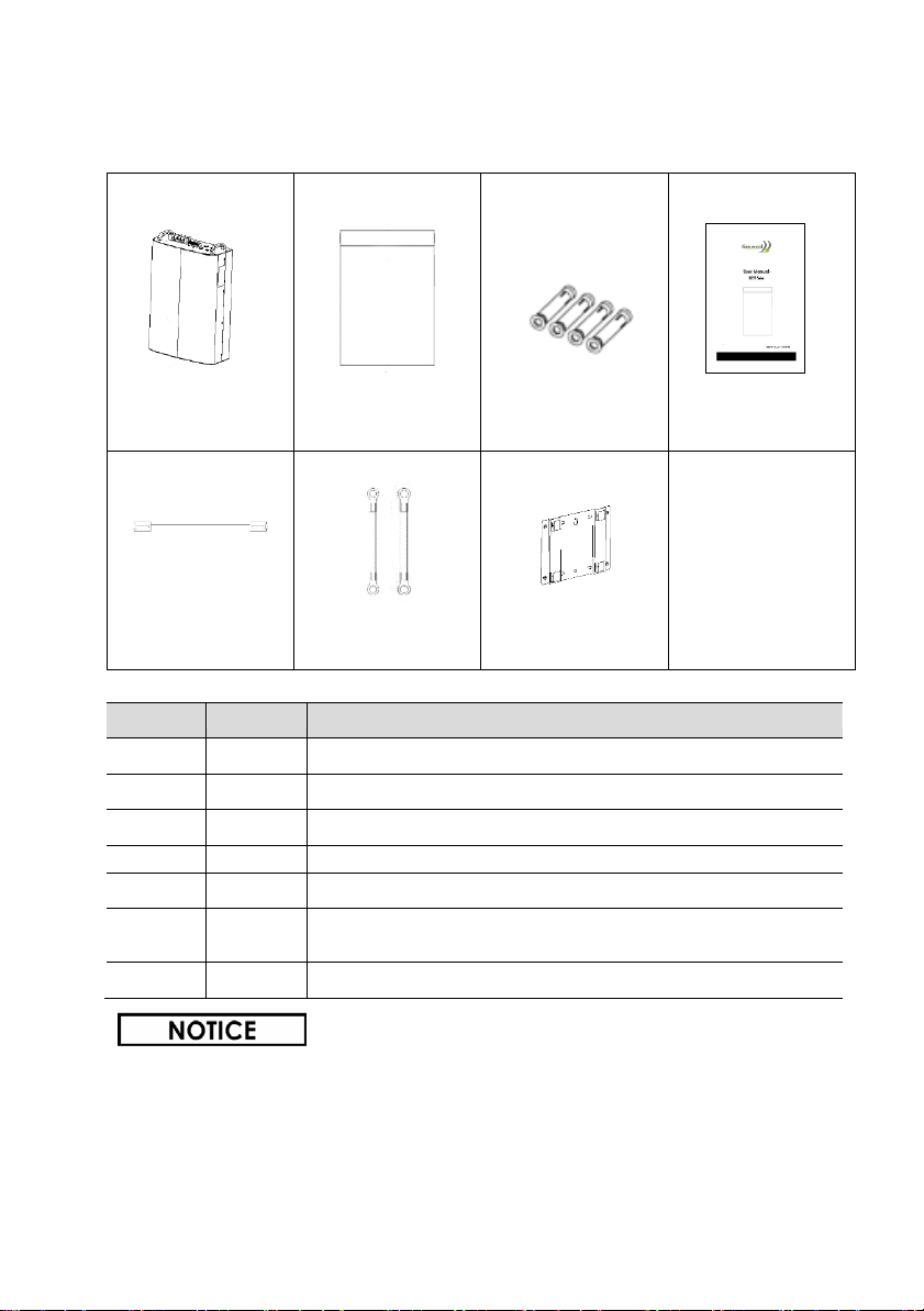
3.
Scope of Delivery...................................................................... 5
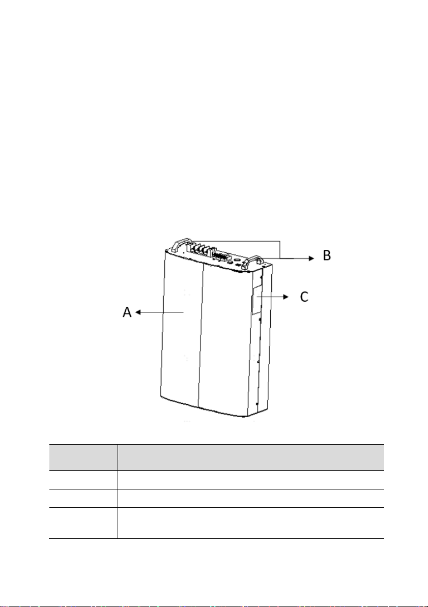
4.
Product Description................................................................... 6
4.1 Appearance for All-in-one Application .............................. 6
4.2 Appearance for Expansion Application............................. 7
5.
Mounting.................................................................................... 9
5.1
Environment Requirements.............................................. 9
5.2 Angle and Space Requirements ....................................... 10
5.3 Mounting the Battery ..................................................... 11
6 Electrical Connection ............................................................. 14
6.1 Overview of the Connection Area............................... 14
6.2 Battery Power Connection............................................ 15
6.3 BMS Communication Connection ............................... 16
6.4 Parallel Connection of Multi-batteries ......................... 17
7 Operating of the Battery ......................................................... 18
7.1 LED Indicator ................................................................... 18
7.2 Turn On/Off the Battery.................................................. 18
8 Technical Data ........................................................................ 19
Contacts: ........................................................................................ 20


1
1.
About This Manual
1.1
Products Covered by This Manual
The manual is valid for GCL Series Li-ion battery: GBLF51-5.
Please read through this manual carefully before operation.
1.2
Target Group
This manual is intended for a qualified electrician. Any electrical
installation and maintenance on the battery must be performed by
qualified electricians in compliance with standards, wiring rules or
requirements of local grid authorities or bodies.
1.3
Symbols Used
The following types of safety precautions and general information
symbols are used in this manual. These important instructions must be
followed during installation, operation and maintenance of the battery.
Symbol
Description
Indicates a hazard with a high level of risk that, if
not avoided, will result in death or serious injury.
Indicates a hazard with a medium level of risk
that, if not avoided, could result in death or
serious injury.
Indicates a hazard with a low level of risk that, if
not avoided, could result in minor or moderate
injury.
Indicates a situation that, if not avoided, could
result in equipment or property damage.
1.4
Storage of the Manual
Please keep the manual properly and operate in strict accordance with all
safety and operating instructions in this manual.
This manual will be updated if necessary. Please check https://gcsolar.co.za
for more information

2
2.
Safety
Please don't crush or impact the battery, and always dispose it according
to the safety regulation.
2.1 Important Safety Instructions
Danger to life from electric shock.
•Before performing any work on the battery, make sure the battery is
power off and the DC isolator is disconnected.
•Do not short connect the DC connectors of the battery, which may cause
electric shock to personnel and damage to the product.
•Do not touch DC connectors of the battery.
•If an error occurs, contact your local distributor or qualified electricians.
•Only authorized service personnel are allowed to install the battery or
perform servicing and maintenance
•The power should be disconnected before attempting any maintenance
or cleaning or working to the battery.
•Do not open the battery or change any components without
authorization, otherwise the warranty commitment for the battery will be
invalid.
•Appropriate methods must be adopted to protect battery from
electrostatic discharge; any damage caused by ESD is not warranted by
the manufacturer.

3
2.2 Response to Emergency Situations
Leaking Batteries
If the battery leaks electrolyte which is corrosive, avoid contact with the
leaking liquid or gas. Direct contact may lead to skin irritation or chemical
burns. If one is exposed to the leaked substance, do these actions:
•
Accidental inhalation of harmful substances: Evacuate people from the
contaminated area, and seek medical attention immediately.
•
Eye contact: Rinse eyes with flowing water for 15 minutes, and seek
medical attention immediately.
•
Dermal contact: Wash the affected area thoroughly with soap and
water, and seek medical attention immediately.
•
Ingestion: Induce vomiting, and seek medical attention immediately.
Wet Batteries or Damaged Batteries
•
If the battery is wet or submerged in water, do not try to access it.
•
If the battery seems to be damaged, they are not fit for use and may
pose a danger to people or property.
•
Please pack the battery in its original container, and then return it to
your distributor
Fire
•
If a fire breaks out where the battery is installed, do these actions:
•
Extinguish the fire before the battery catches fire;
•
If the battery has caught fire, do not try to extinguish the fire.
•
Evacuate people immediately

4
2.3 Limitation of Liability
Any product damage or property loss caused by the following
conditions GRWOCOL does not assume any direct or indirect liability.
• Product modified, design changed or parts replaced without
GRWOCOL authorization;
• Changes, or attempted repairs and erasing of series number or seals
by non GRWOCOL technician;
• System design and installation are not in compliance with standards
and regulations;
• Failure to comply with the local safety regulations;
• The Product has been improperly stored in distributor’s or end user’s
premises;
• Transport damage (including painting scratch caused by movement
inside packaging during shipping). A claim should be made directly to
shipping or insurance company as soon as the container/packaging is
unloaded and such damage is identified;
•Failure to follow any/all of the user manual, the installation guide
and the maintenance regulations;
•Improper use or misuse of the device;
•Insufficient ventilation of the device;
• The maintenance procedures relating to the product have not been
followed to an acceptable standard;
• Force majeure (violent or stormy weather, lightning, overvoltage, fire
etc.)
• Damages caused by any external factors.

5
3.
Scope of Delivery
Battery A
Battery B
C
D
E(for Battery B)
F(for Battery B)
G(for Battery B)
Item
QTY
Designation
A
1
Battery (All-in-one Application)
B
1
Battery with battery-cover (Expansion Application)
C
4
Screws for Fixing Mounting Bracket
D
1
User Manual
E
1
BMS cable (Expansion Application)
F
2
Power cable (Expansion Application , Red for positive,
black for negative)
G
1
Battery-Bracket(Expansion Application)
The Battery A or B is suitable for different applications, and the accessories in
the package (marked with "A" or "B") are also different. Please confirm the
application before purchase and check the accessories before installation.

6
4.
Product Description
The GCL Series battery is a series of Low Voltage Lithium-ion battery. It is
designed for residential and commercial energy storage system. It must
only be connected with a GRWOCOL hybrid inverter.
To prevent personal injury and property damage and to ensure long- term
operation of the product, please read and follow all the instructions and
cautions on the battery and this user manual during installation,
operation or maintenance at all times.
4.1 Appearance for All-in-one Application
Position
Designation
A
Battery
B
Handles for the battery
C
Nameplate Label: Clearly identify the product,
including the SN, technical data, certifications, etc.

7
4.2 Appearance for Expansion Application
Position
Designation
A
Connection Area Cover (Battery-cover)
For All-in-one application with hybrid inverter, this cover
is not needed.
B
Nameplate Label: Clearly identify the product, including
the SN, technical data, certifications, etc.
If the battery is not used or not installed for a long time, it is recommended
to measure the voltage and charge it before use for better maintenance.

8
Icons on the Nameplate
Symbol
Explanation
Caution, Risk of Danger
Caution, Risk of Electric Shock
Refer to the Operating Manual
WEEE Mark. This battery should not be
disposed as ordinary waste.

9
5.
Mounting
5.1
Environment Requirements
Check to make sure the installation site does not fall into any of the
following conditions: If any do, then a risk assessment will be required.
•Unsafe due to assessment of occupational health safety risks.
•The ambient temperature is outside the range of tolerable ambient
temperature(-20°C to +50°C, -4°F to +122°F).
•Close to flammable materials or areas where flammable materials are
stored.
•Prone to be damaged by sea water.
•Prone to be flooded or high levels of snow falls.
•Close to corrosive gas or liquid (for example, locations where chemicals
are processed or stored).
•Exposed to direct sunlight or in an enclosure exposed to direct sunlight.
•Little or no air flow
•Mounted on a surface without suitable fire/heat rating.
•Mounted on a wall without suitable load holding capacity.
•High humidity.
•Sites considered unsafe because of local regulations.
•Confined space without adequate airflow.
•Area subject to sand or dust storms.
•Exposed to steam, vapor, or water.
Installation and maintenance personnel must operate according to
applicable federal, state and local regulations as well as the industry
standard. The product installation personnel shall wear safety gears,
etc. in order to avoid short circuit and personal injury.

10
5.2 Angle and Space Requirements
Never install the Battery horizontally, or with a forward tilt or with a
backward tilt or even with upside down. Install the battery upright or at a
maximum back tilt of 15 degrees to facilitate heat dissipation.
This battery is indoor version and can be only installed in an indoor location.
The space around batteries recommended refer to the figure below

11
5.3 Mounting the Battery
5.3.1 Unpacking and Check for Transport Damage
Unpacking the battery package and make sure the battery is intact during
transportation. If there are some visible damages, such as cracks, or
missing, please contact your dealer immediately.
5.3.2 Procedure for All-in-one Application
The battery bracket, power cables, and BMS cables are along with the
inverter in the inverter package. For more detailed information and
installation steps, please refer to the inverter user manual.
5.3.2 Procedure for Expansion Application
STEP 1: Anchor Battery Bracket
•Plan and measure the distance between system components and
determine whether cables will be routed into the system from the top,
bottom, or side of the enclosure before installation.
•Make sure the wall is strong enough to withstand the weight of battery.
•Take out the Wall-mounting Bracket (battery-bracket) and locate the
appropriate drilling holes, then mark it with a marker pen.
•Drill holes with driller, make sure the holes are deep enough (at least
60mm) to support the battery.

12
Product back dimension drawing
STEP 2: Screw the bracket on the wall
•
Use expansion bolts or correct wall
fixings to attach the mounting bracket
on the wall tightly.

13
STEP 3: Mount the Battery to the Bracket
•Lift and hang the battery to the battery-
bracket and ensure that the two mounting
ears perfectly engage with the battery -
bracket.
STEP 4: Open the Connection Area Cover
•Pull out the front cover of the wiring area, unscrew the upper cover
and open the upper cover, then connect the battery cable and the
BMS communication cable (refer to in Chapter 6).
STEP 5: Install the Connection Area Cover
•After the electrical connections is finished, put on the upper cover of
connection area and lock the screws and then push in the front cover.

14
6Electrical Connection
6.1Overview of the Connection Area
Position
Designation
A
Grounding Port
B
Battery Power Ports
C
DC Isolator
D
LED Indicator
E
Power Switch
F
BMS Ports

15
6.2Battery Power Connection
Battery connection diagram (All-in-one Application)
Procedure:
Before connecting the power cables, make sure the DC isolator of the
battery is disconnected.
STEP 1:
• Install the connectors to battery power
ports; make sure the polarities are correct.
STEP 2:
•Plug the other ends of power cables into
inverter. Please contact with your inverter
vendor for detailed information.

16
6.3BMS Communication Connection
Please check whether the BMS communication cable in the accessory
box is appropriate for the battery. If you are not sure for that, please
confirm with your vendor.
Procedure:
STEP 1:
•Please insert the RJ45 connector into the BMS port of battery.
STEP 2:
•Please insert the other end of the cable in the corresponding port of
inverter.
BMS Connector Pin Definition:
1. BMS_CAN_H
2. BMS_CAN_L
3. BMS_485_A
4. GND
5. BMS_485_B
6. GND
7. Researved
8. Researved
Table of contents