GRUNDFOS ALLDOS U 189-010 Manual

115.710057-V3.0
U 189-010 en
Vacuum Change-over Device
U 189-010
Technical Information

2V3.0
U 189-010 en
Imprint
Vacuum Change-over U 189-010
Technical Information
Version 3.0
Publisher:
ALLDOS Eichler GmbH
Reetzstraße 85 • 76327 Pfinztal (Söllingen)
Postfach 1160 • 76317 Pfinztal
Tel. +49 72 40 61-0 / Fax. +49 72 40 61-211
Mail: [email protected]
Internet: www.alldos.com
© 2007 by ALLDOS Eichler GmbH
Subject to change.

315.710057-V3.0
U 189-010 en
Installation Data
NOTE Please fill in this form following commissioning. It will help you
and your GRUNDFOS Alldos servicing partner to adjust the
device during subsequent corrections.
Owner:
GRUNDFOS Alldos customer No.:
Contract No.:
Order No. of device:
Serial number of device:
Put into service on:
Location of device:
Used for:
Installation Diagram

4V3.0
U 189-010 en
CONTENT PAGE
1 Of General Interest 5
1.1 General Notice 5
1.2 Safety Instructions 5
2 Construction and Function 6
3 Technical Data 6
3.1 Electrical Data of Remote Indicator 6
4 Installation 6
5 Commissioning 8
5.1 Leak Test of the Vacuum Side 8
5.2 Leak Test of the Pressure Side 8
5.3 First Commissioning 8
5.4 Checking the Change - Over Function 8
6 Fault Correction 9
7 Spare Parts Set 9

515.710057-V3.0
U 189-010 en
1 Of General Interest
1.1 General Notice
This Technical Information contains instructions for the
installation, commissioning as well as attendance and
maintenance of the vacuum change - over device described
in this manual.
For reasons of clarity, however, this document neither
takes into consideration complete details concerning each
variant nor every conceivable case of installation and
operation.
If you require further information or any problems arise
which are not reflected in detail in this manual, contact
ALLDOS directly for the information needed.
Furthermore we want to point out that the warranty in
accordance with our general terms of sale and delivery
shall only be valid, if the installation is implemented exclu-
sively by an authorized and suitably qualified personnel.
The safety instructions and recommendations given in this
technical information have strictly to be observed.
1.2 Safety Instructions
The safety instructions
WARNING
,
CAUTION
and
NOTE
em-
ployed in this technical manual have the following meaning:
WARNING This heading is used, if inexact observance or
non-observance of operating instructions,
work instructions, the stipulated sequence of
work and suchlike can result in injuries,
accidents or death.
CAUTION This heading is used, if inexact observance or
non-observance of operating instructions,
work instructions, the stipulated sequence of
work and suchlike can result in damage to the
device.
NOTE This heading is used, if the user attention is to
be drawn to an exceptional feature.

6V3.0
U 189-010 en
2 Construction and Function
The vacuum change - over device U 189-010 ensures a con-
tinuous gas supply for gas dosing systems by changing the gas
supply over in time from the empty supply battery to a stand - by
battery.
The vacuum change - over device is operable without auxiliary
power. From which battery the gas is supplied, is indicated visu-
ally, but as an option the change - over position can also be
remote indicated via 2 reed contacts.
As soon as the vacuum rises to a value of about 3 - 4 m WS /
78" - 118" WC, which can be caused by an empty or closed
supply battery, the change - over function is triggered.
The change - over device can be used in connection with the
chlorine dosing units C 105 and V 107 or V 115.
NOTE If the chlorine gas dosing units V 107 and
V 115 are retrofitted with the change - over de-
vice, a compensation for the main regulator
has to be provided.
3 Technical Data
Medium Cl2, SO2
Maximum flow rate 10 kg/h Cl2, SO2
500 PPD Cl2, SO2
Minimum flow rate ≥50 g/h Cl2, SO2
≥2.5 PPD Cl2, SO2
Optional connections ➜PE - tube 8 x 11
for max. 4 kg/h Cl2, SO2
➜PE - tube 10 x 14
for max. 10 kg/h Cl2, SO2
➜PVC - pipe DN 10
for max. 10 kg/h Cl2, SO2
➜PE - tube 1/2" od.
3/8" NPT threaded
up to 200 PPD (USA)
➜PE - tube 3/8" od.
3/8" NPT threaded
up to 500 PPD (USA)
Materials PVC / Viton / FEP / glass
silver / Hastelloy C
Weight about 2 kg
3.1 Electrical Data
for option with 2 reed contacts for remote indication
Supply voltage max. 75 V DC / 50 V AC
Power consumption 1 A
Wattage max. 50 W
4 Installation
Connect the vacuum change - over device at the inlet side to
two vacuum regulators and at the outlet side to the chlorine gas
dosing unit. The inlet connections for the vacuum regulators are
marked with the inscriptions IN I and IN II, the connection for
the chlorine dosing unit with OUT.
The vacuum lines between the vacuum regulators and the
change - over device should be kept as short as possible and
should not exceed a maximum length of 6 m. Thus a minimum
pressure loss can be ensured.
A precondition for trouble - free functioning of the vacuum
change - over device is the tightness of all lines and connec-
tions.
☞see 5.1 / 5.2 Leak test
The vacuum change - over device should be installed as de-
picted in figure 1 on the following page.

715.710057-V3.0
U 189-010 en
16
234578
Figure 1 Functional scheme and connection chart of a chlorine gas dosing system
with vacuum change - over device 189-010
1
Gasdetect
2
Adsoroption filter
3
Vacuum regulator with liquid trap
4
Vacuum change - over device
5
Chlorine drum
6
Chlorine drum support
7
Chlorine gas dosing unit
8
Injector
8

8V3.0
U 189-010 en
5.3 First Commissioning
After the leak test has been terminated successfully, the
vacuum change - over device can be commissioned.
1Entirely open the connecting valves of the drums or
cylinders.
2Start the injector. Thereafter chlorine gas is dosed. The
position of the indicator pin of the change - over device
signals from which battery the chlorine gas is supplied.
5.4 Checking the Change - Over Function
1Open all cylinders or drums and start the injector.
2Close the supply battery that is in operation.
3The change - over device switches the gas supply over
to the stand - by battery after a short period of time (that
depends on the dosing quantity and the length of the
line).
4Then check, if the changing over from the stand - by
battery to the former supply battery functions, as well.
5Open again all cylinders or drums. The vacuum change
- over device is now ready for operation.
5 Commissioning
After having completed the installation continue ommissioning
the change - over device.
WARNING The device must be commissioned only by
qualified personnel strictly complying with the
instructions for handling the hazardous sub-
stance chlorine. The qualified staff must wear
protective clothing and gas mask when doing
the work described in the following.
NOTE Prior to the initial starting all parts carrying
chlorine gas have to be checked for leaks.
5.1 Leak Test of the Vacuum Side
1Close the connecting valves of the drums or cylinders.
2Start the injector. Thereupon the vacuum lines are
evacuated and in this operating state the change - over
device switches uncontrollably.
3After about 10 minutes (depending on the length of the
vacuum lines and on the setting of the adjusting valve)
the rotameter must not indicate a flow.
4If the rotameter yet indicates a flow, the complete dosing
system must be checked for possible leaks.
Warning As precondition for the leak test the chlorine
gas dosing unit must be evacuated and free of
chlorine gas and the injector be in operation.
5To check the single components of the dosing system,
disconnect the vacuum lines between the vacuum regu-
lators and the rotameter one after the other and close
them tight with the finger.
6If the rotameter stops indicating a flow after having dis-
connected one of the vacuum lines, the leaks has to be
at the disconnected component.
5.2 Leak Test of the Pressure Side
1Stop the injector.
2Open the connecting valves of the drums or cylinders by
about one revolution.
3Check the connecting parts and inlet valves of the
vacuum regulators for leaks by means of ammonia.
Leaks are localized by passing the bottle with ammonia
close by the relevant parts and squeezing a little bit of
ammonia gas out of the bottle. If there is chlorine gas
escaping anywhere, white vapour develops.
WARNING Even the slightest detected leaks have to be
removed immediately.

915.710057-V3.0
U 189-010 en
6 Fault Correction
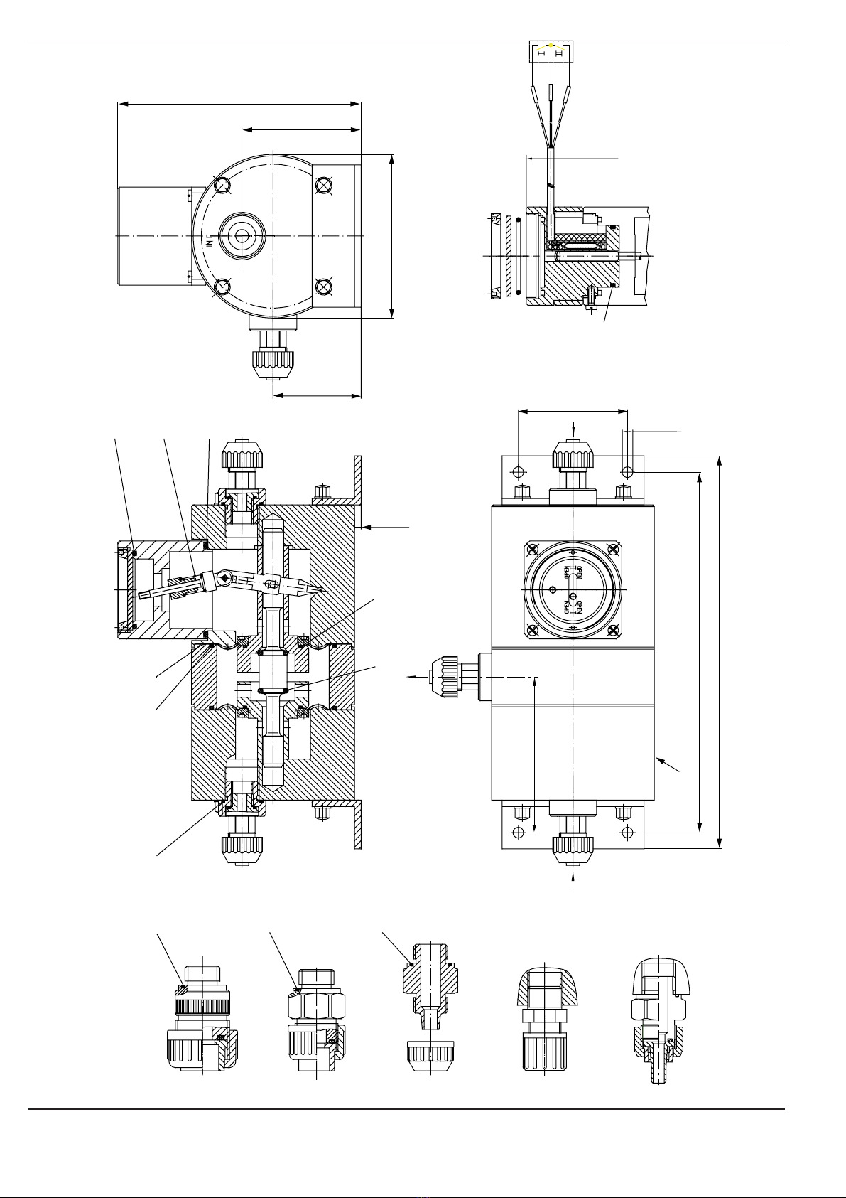
The numbers in brackets occurring in the following refer to the
items of the enclosed sectional drawings 15.189-200 and
12.4188-300.
FAULT
No changing over
The change - over device
switches to the stand - by bat-
tery despite filled cylinder or
drum and opened connecting
valve.
CAUSE
●The gas dosing system is
leaky, so that the vacuum
required for the change - over
function cannot be gener-
ated.
●The change - over device is
coupled with a chlorine gas
dosing unit V 107 or V 115,
without having provided a
compensation for the main
regulator.
●The diaphragm (2) or o - ring
(3) in the change - over de-
vice are leaky.
●The vacuum regulator lets
through only an insufficient
amount of chlorine or the
vacuum line is too long (this
fault occurs mainly with a
high flow rate). It can also be
the case that a chlorine cyl-
inder is frozen up.
●Using the change - over de-
vice in connection with the
vacuum regulator C 105-230
(all vacuum system) the flow
rate of each regulator can
exceed 600 g/ h or 30 PPD.
DISCERNIBLE FROM
☞The rotameter indicates a
flow, although the supply bat-
tery (cylinder, drum) is empty
or closed.
☞The vacuum of 2 - 3 m WS /
52" - 78" WC required for the
change - over function is not
attained (measure the vacu-
um between change - over
device and regulator with a
vacuum meter).
☞The rotameter indicates a
flow, although the supply bat-
tery (cylinder, drum) is empty
or closed.
☞Measure the vacuum after
the outlet of the change -
over device with a vacuum
meter. The vacuum must
amount to less than 2 m WS /
52" WC.
☞Measure the vacuum after
the outlet of the change -
over device with a vacuum
meter. The vacuum has to
be less than 2 m WS / 52" WC.
Adjust a smaller flow rate, so
that the value of the operat-
ing vacuum falls below that
of the vacuum required for
the change - over function.
CORRECTION
☞Check the dosing system for
leaks. For this purpose dis-
connect the vacuum lines
between the rotameter and
the vacuum regulators one
after the other, close them
with the finger and observe
the rotameter. See sections
5.1 and 5.2 Leak test.
☞Arrange a compensation for
the main regulator.
☞Replace the defective parts.
☞Clean the vacuum regulator
and restart it or lay a vacuum
line with a larger cross sec-
tion.
☞Add a further vacuum regu-
lator with chlorine cylinder to
the supply battery, if the
maximum flow rate is re-
quired.
7 Spare Parts Set
There is a spare parts set, order no. 553-1024 available for
the vacuum change - over device U 189-010. It comprises the
o - rings (1 / 3 / 4 / 5 / 7 / 8 / 9), the diaphragm (2) as well as the
pressure spring (6). If other than the indicated parts are defec-
tive, return the change - over device to the works for repair or
replacement.

10 V3.0
U 189-010 en
21.6
21.6
21.6
21.6 51.25 26
51.3
7
51.8
51.13
51.14
29.5
149.2 (57/8’’)
73 (3’’)
139 (51/2’’)
100 (4’’)
54 (21/8’’)
67 (25/8’’)
220.5 (811/16’’)
240.5 (915/32’’)
4 (5/32’’)
6.5 (1/4’’)
95.25 (33/4’’)
white
brown
gas inlet II
green
15.189-200
gas inlet I
gas outlet
type plate
connection
USA 1/2"
sealed with
Teflon strip
connection
PVC pipe DN15
connection
PVC pipe DN10
connection
PE 12 x 16
connection
10 x 14
length 3 m
Signal transmitter for remote indication
see drawing no. 12.4188-310
spare parts set: 553-1024

1115.710057-V3.0
U 189-010 en
green
white
brown
12.4188-310
length 3 m
Signal transmitter for remote indication
switch direct voltage max. 1,0 A
contact load max. 50 W
switch direct voltage 75V
switch alternating voltage 50 AC

12 V3.0
U 189-010 en
Table of contents