Gryphon C-40 User manual

Your new Gryphon Diamond Band Saw is warranted for one year from date of purchase. All mechanical parts with the
exception of the blade, blade guide and sponge are guaranteed against failure for one year. If such a failure occurs for any
reason other than abuse or misuse during this period, it will be repaired (or at our option replaced) free of charge FOB our
factory. Retain your sales receipt for proof of purchase. Should repairs ever be required, return the saw to
Gryphon Corporation.
© 1997 Gryphon Corporation
12417 Foothill Blvd. • Sylmar • California • 91342 • (818) 890-7770
Instructions
Gryphon
Diamond Band Saw
model C–40
Safety Precautions
• Always wear eye protection •
• Do not run blade dry •
• Keep ngers clear of moving parts •
• Lift off motor when cleaning
D
i
a
m
o
n
d
B
a
n
d
S
a
w
M
o
d
e
l
C
M
a
d
e
i
n
U
S
A
®

Chassis
Platform
Blade
Lower Shaft Assembly
Post
Post
D
i
a
m
o
n
d
B
a
n
d
S
a
w
M
a
d
e
i
n
U
S
A
®
Cover Collar
Upper Wheel Motor Cradle Motor
Cap
Slide
Slide
Support Bar Adjustment
Screw
Motor Cover
Guard
Collar
Guide
Holder
Guide
Pivot Screw
DO NOT TWIST
Pivot Screw
DO NOT TWIST
Lower Shaft Screw
Lower
Shaft
Screw
O-Rings O-Rings
Adjustment
Screw
Lower Wheel
Band
Band
Spring
Upper Guide Holder
Guide
Washer
Washer

Read this before sawing ~ 40 mile per hour blade speed
CONGRATULATIONS
You have purchased the world’s fastest diamond band saw. The cutting speed approaches but just stays under the
speed limit where glass underwater glows during cutting.
PRECAUTIONS
Keep your ngers away from the moving blade
Keep your water level near the top of the sponge in the water tray (see page 6). As this sponge wears the amount
of cooling water delivered to your glass is reduced and glass damage will occur. If the glass you are cutting appears dry,
change the sponge. Sponges should be 1/2” thick.
Do not bend or kink your blade. Heavy saw vibrations result from running bent blades.
Use only Gryphon #301 blades on this high speed saw. Blades from other manufacturers cannot withstand 40 m.p.h.
Other blades usually make the saw vibrate and run at a high noise level because of their poor quality. After 2 to 4 hours
of running time other blades will break.
Your saw warranty is separate from your blade warranty. See the blade box for blade warranty.
You own a high speed tool. We urge you to read the instructions entirely.
Index
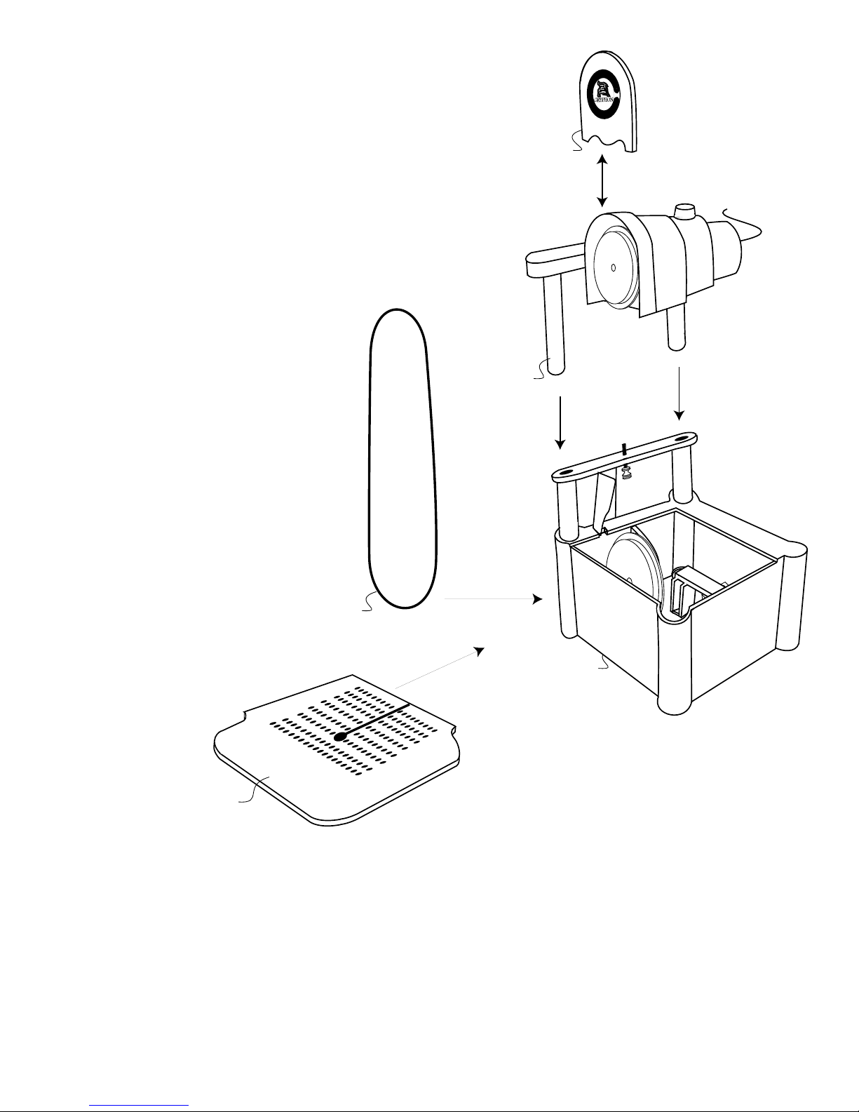
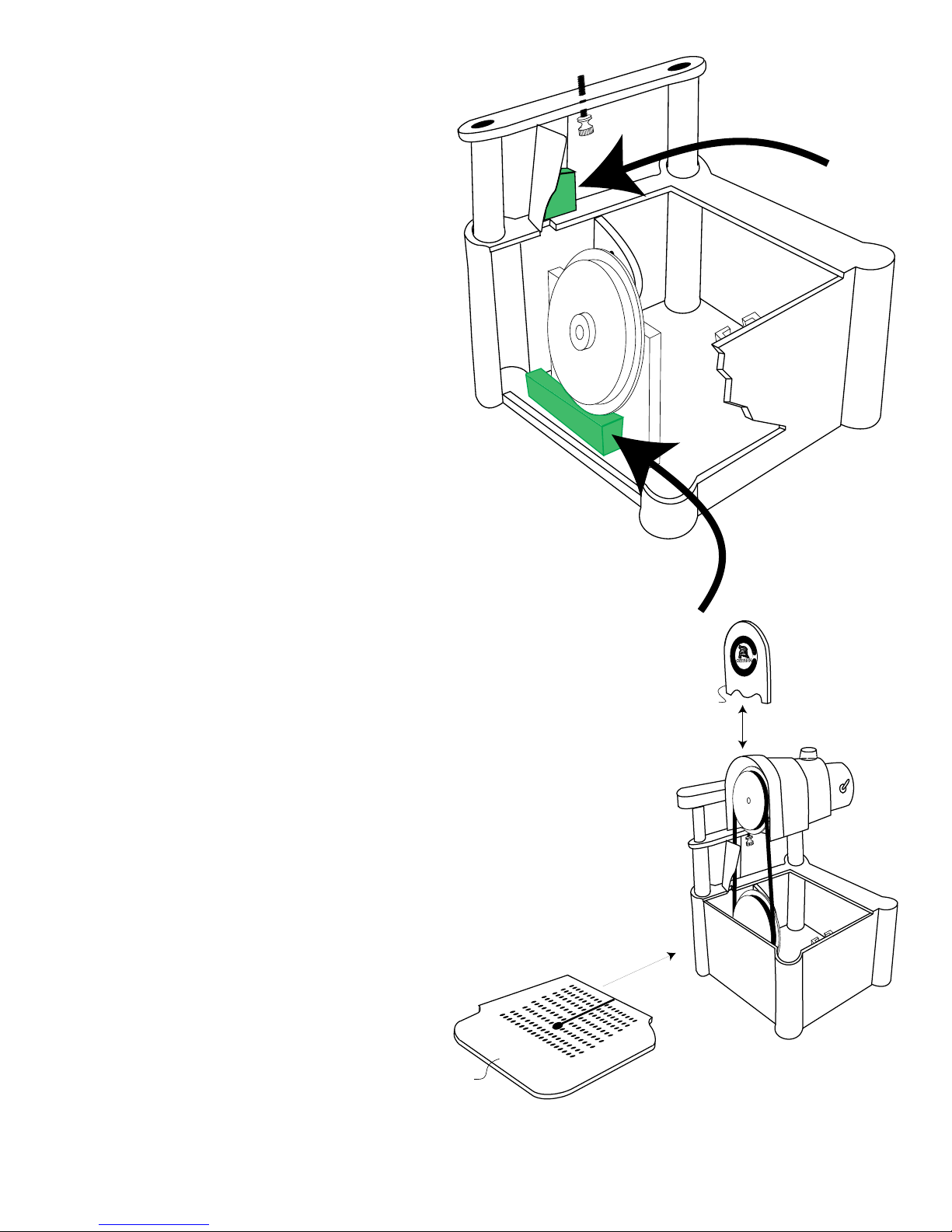
Assembly ................................................................................................................................... 4
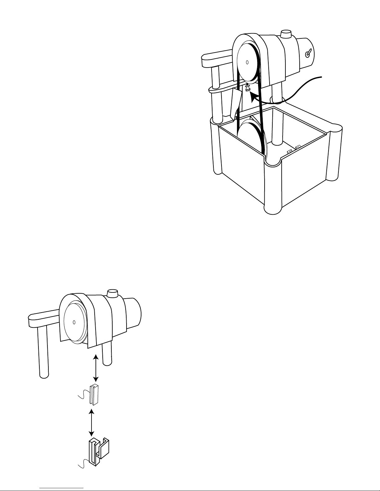
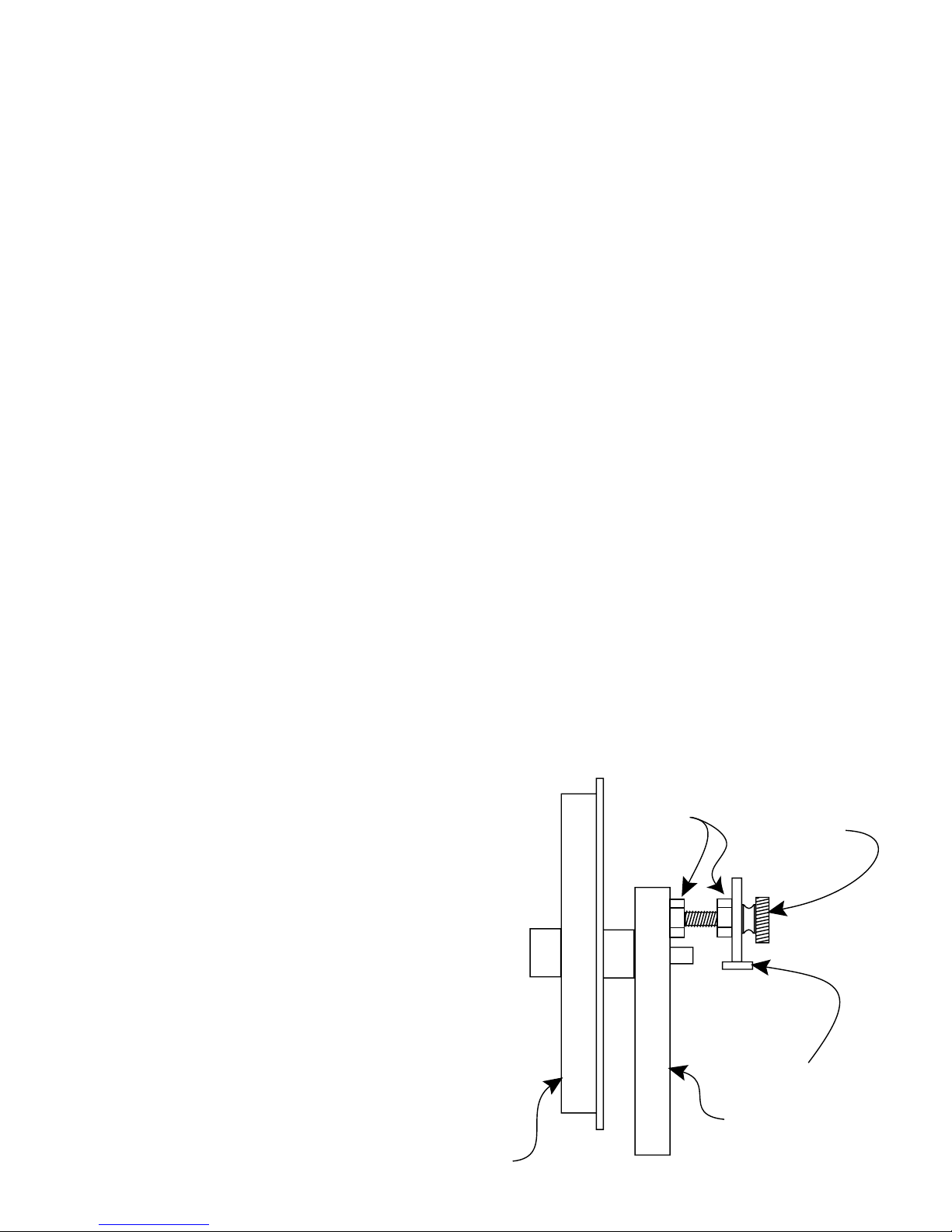
Blade Installation ................................................................................................................... 4
Cleaning the Saw ................................................................................................................... 7
Cutting Glass .......................................................................................................................... 6
Cutting Other Materials ....................................................................................................... 7
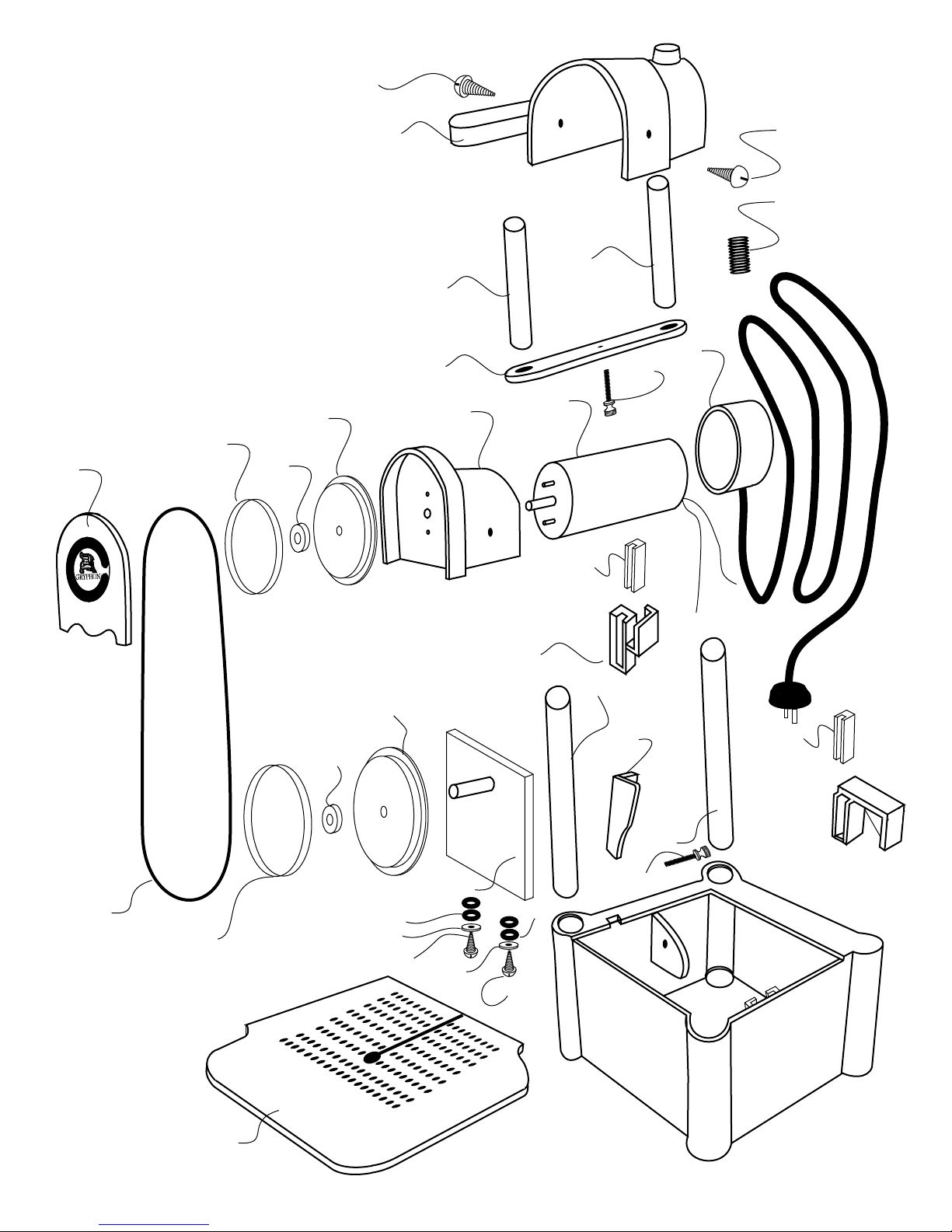
Exploded View ................................................................................................................... 2
Lower Guide Installation ........................................................................................................ 5
Marking your Pattern ................................................................................................................. 6
Platform & Cover Installation ................................................................................................. 6
Read this before sawing --- 40 mile per hour blades ............................................................ 3
Replacement Parts ................................................................................................................... 8
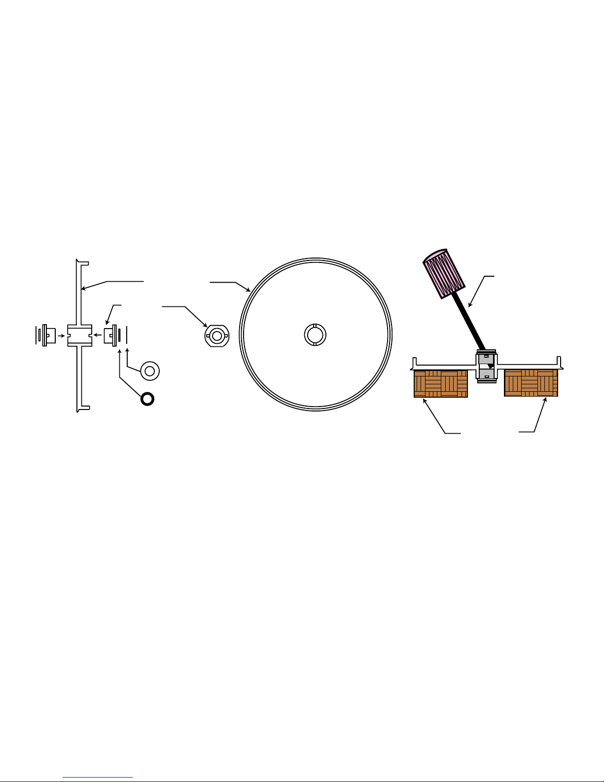
Replacing Lower Wheel Adjustment Screw ............................................................................ 7
Replacing Lower Wheel Bushing .............................................................................................. 8
Safety Precautions ................................................................................................................... 1
Sponge and Water Installation .................................................................................................. 6
Trial Run & Blade Adjustment ................................................................................................. 5
Unpacking .................................................................................................................................. 4
Upper Guide Installation .......................................................................................................... 5
Warranty ....................................................................................................................................... 1

Unpacking~
Your shipping carton contains the following parts:
• Top Assembly
• Bottom Assembly with Guide Holder installed
• Platform
• Blade (coiled in box)
• Upper Blade Guide Holder
• 3 Guides
• Two Sponges
• Spare Lower Adjustment Screw and two nuts*
• These Instructions
DO NOT turn either Adjustment Screw.
These are preset for your Blade at
the factory.
The use of these Adjustment Screws is
explained further on in this booklet.
Assembly~
Assembly is very simple.
Refer to the drawing on this page.
• Remove tape used in packing.
• Insert Slides on Top Assembly into
Posts on Bottom Assembly as shown.
• Push Top Assembly down as far as
it will go (note that the Adjustment
Screw controls
how far down
the Top Assembly
will go). Do not
turn the Upper
Adjustment Screw
yet.
• Remover Cover
by sliding it straight up.
Blade Installation~
• Remove coiled Blade from box.
• Uncoil the Blade gently. Do not bend or kink the Blade.
• Place Blade under Lower Wheel with diamond side towards the front of the saw.
• Place Blade at 9 O’clock position on Upper Wheel and rotate Upper Wheel by hand clockwise to wrap the
blade over the Upper Wheel. Blade should pass through slot in Guide.
• Turn Upper Wheel by hand until the Blade walks to the back of the Upper Wheel.
Bottom Assembly
D
i
a
m
o
n
d
B
a
n
d
S
a
w
M
a
d
e
i
n
U
S
A
®
Slide
Top Assembly
Cover
Blade
Platform

Trial Run & Blade Adjustment~
• Route power cord through the slot provided in Top
Assembly and plug into a standard grounded outlet.
The upper Adjustment Screw was factory set. Use the
following steps to make your own adjustment.
• While pressing down gently on the back of the Motor
(to keep tension on the Blade), ip the on/off switch
to the “on” position.
• By tightening the Adjustment Screw you raise the
Motor back and bring the Blade toward the front
of the Upper Wheel. Loosening this screw will bring
the Blade towards the back of the Upper Wheel.
• Tighten the Adjustment Screw until the blade has
minimum wobble but stays in the Guides. If the saw
becomes louder and vibrates, loosen the Adjustment
Screw until the saw quiets down.
• You will not need to adjust the Lower Adjustment
Screw. This control for the tilt of the Lower Wheel was
set at the factory and should not require further
attention.
• Turn the saw off.
Lower Guide Installation~
• Your saw was shipped with the Guide Holder in place. If it has become loose or fallen out in shipment, reinsert it
into slot on inside wall of Chassis. Push rmly into place so that top of Guide Holder is ush with top of Chassis.
• Slide one Guide into slot on Guide Holder (slot on Guide must face out).
• Blade ts in slot of Guide.
Upper Guide Installation~
• Install a Guide into the Upper Blade Guide Holder in the same way as you
installed the Guide into the Lower Guide Holder.
• Install the Upper Blade Guide Holder onto your band saw by inserting it
over the rear right-hand corner of the Motor Cradle as shown.
• The Upper Blade Guide Holder may be removed or reinstalled at any
time.
On
Off
On
Adjustment
Screw
Blade Guide
Upper
Blade Guide
Holder

Sponge and Water Installation~
• The sponges reduce the water splash.
• Wet both Sponges.
• Insert sponges in locations shown in cutaway
drawing at right. Ridges are molded into the
saw to keep the sponges in place.
• Pour water into chassis. Water level should not
be higher than the top of the bottom sponge.
The use of a corrosion inhibitor or other
additive in the water is not recommended as it
will not benet the function of the saw.
• Rotate or replace sponges when worn.
• Additional sponges can be cut from a standard
kitchen sponge available at your grocery store.
Platform & Cover Installation~
• The Platform is installed with the texture side
up.
• When installed, the Platform surface will be
ush with the top of the Chassis.
• Install the Platform by sliding it into place as
shown. Be very careful not to nick or bend the
Blade while installing the Platform.
• The Cover, which you removed to install the Blade, is reinstalled simply by sliding
it down the front of the Top Assembly until it sits ush.
Marking your Pattern~
Since the Blade carries cooling water to the glass surface, your pattern will need
to be resistant to water. The best technique is to mark your pattern on the glass with a
thin-line paint marker (such as the Gryphon Pattern Marking Pen). These are available from
your dealer, or similar products can be obtained from artist’s supply houses.
Cutting Glass~
When cutting, push your work with only a mod-
erate pressure. Very heavy pressure will not result in
faster cutting, and may bend the blade. When cutting
curves, use only a light pressure and let the blade do
the work. Aggressive pressure against the blade when
cutting curves causes rapid wear to the back of the blade.
Do not force the blade to follow a pattern, but rather guide the work through the blade. This will insure you of the longest
possible blade life. When backing out of a slot, turn motor off. Hold your thumb against the front of the blade while carefully
Top Sponge
Bottom
Sponge
Platform
D
i
a
m
o
n
d
B
a
n
d
S
a
w
M
a
d
e
i
n
U
S
A
®
Cover

Platform
D
i
a
m
o
n
d
B
a
n
d
S
a
w
M
a
d
e
i
n
U
S
A
®
Cover
backing the glass. Remove your thumb and start the motor.
It is normal for a blade to cut more slowly as it wears. Some materials, such as lead crystal, load the blade and cutting
action slows signicantly after a time. Good cutting action will be immediately restored with only a little cutting into a piece
of clear window glass, silicon carbide, or a brick.
Cutting Other Materials~
The diamond blade on your band saw is useful for cutting a variety of hard materials. Stone, tile, ceramics and
similar materials can be cut as easily as glass. The speed at which the saw cuts will be determined by the thickness and the
hardness of the material being cut. Harder materials will wear the blade faster. Metals are too soft to be cut by a diamond
blade and will gum up the blade.
Cleaning the Saw~
The glass dust that results from your cutting is carried to the bottom of the saw where it combines with the water to
form a slurry. When the water becomes objectionably dirty you should clean out this slurry as follows:
• Remove Platform & Cover.
• Remove Blade.
• Remove Top Assembly by pulling straight up.
• Pour out dirty water outside. Do not pour into plumbing as the slurry can cause clogs.
• Use a paper towel to remove heavy slurry if required.
• Rinse out Bottom Assembly with a garden hose if desired.
• Do not use solvents to clean any part of the saw. Soapy water is all that is required.
• If you remove the Guide Holder, clean it thoroughly before replacing to insure that it ts ush.
Replacing Lower Wheel Adjustment Screw~
If it should ever become necessary to replace the
Lower Adjustment Screw (used for adjusting the tilt on the
Lower Wheel), proceed as follows:
(1) Remove old Lower Adjustment Screw and both
nuts (the rear nut is glued to the knob, and
the easiest way to remove it is by cutting it
off with a sharp knife).
(2) Pass new Lower Adjustment Screw through
hole in plastic arm.
(3) Twist two nuts half way onto Lower Adjustment
Screw.
(4) Screw Lower Adjustment Screw into hole in
Lower Shaft Assembly.
(5) Twist nut nearest the Plastic Arm so that it
almost touches Plastic Arm, but still allows
knob to turn.
Lower
Wheel
Lower
Adjustment
Screw
Locking
Nuts
Plastic
Arm
Lower Shaft
Assembly

(6) Install the blade and rotate the Upper Wheel by hand while turning Lower Adjustment Screw in or out until the
blade runs near the shoulder at the back of the Lower Wheel.
(7) Turn saw on and twist Lower Adjustment Screw until blade runs quiet and almost touches shoulder of Lower
Wheel.
(8) Tighten both Locking Nuts.
Replacing Lower Wheel Bushing~
If it should ever become necessary to replace the Lower Wheel Bushing, proceed as follows:
(1) Remove the Lower Wheel by rst removing the stainless steel collar at the front of the wheel shaft, then pull the
Lower Wheel and all the washers and O-rings off of the shaft.
(2) Wipe the shaft clean and, if necessary, clean up the shaft with steel wool. Lubricate the shaft thinly with Vasoline.
(3) Pull the old bushings out of the Lower Wheel with pliers*.
(4) Push the new bushings into the Lower Wheel so that the bushing ears slip into the notches in the wheel hub. Put
the assembly on the oor and step on it to rmly press the bushings into position.
(5) Push new O-rings into the recesses in each bushing.
(6) Place on shaft:
(a) Lower Wheel (be sure that the front O-ring stays in the recess)
(b) collar
Push the above group of parts tightly against the Lower Shaft Assembly. Tighten the set screw.
Replacement Parts~
Genuine Gryphon Diamond Blades and Blade Guides are available through your dealer. Replacement Sponges are
available in most grocery stores. For other parts or warranty service, contact the factory in Sylmar, California.
Gryphon Corporation.
© 1997 Gryphon Corporation
12417 Foothill Blvd. • Sylmar • California • 91342 • (818) 890-7770
O-ring
Teflon
Washer
Bushing
Lower Wheel
Wood Block
Screw Driver
Table of contents
Other Gryphon Saw manuals
Popular Saw manuals by other brands

Bosch
Bosch GKS 190 Professional Original instructions

DeWalt
DeWalt D364-O4 instruction manual

6K Products
6K Products DH0630 Operation and parts manual

Baumr-AG
Baumr-AG BTS90 user manual

Craftsman
Craftsman 21239 - 12 in. Sliding Compound Miter Saw Operator's manual

Norton
Norton TR 230 GL Operating instructions and spare parts list