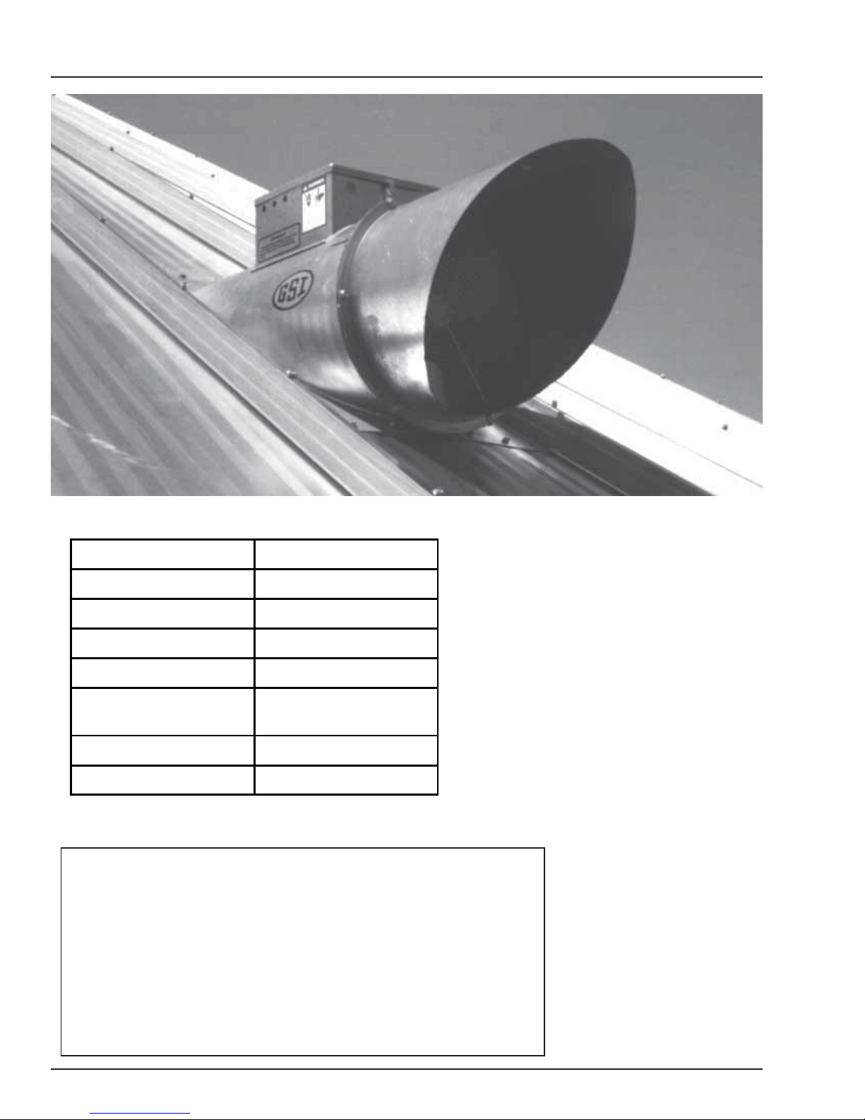
GSi PNEG-524 User manual

Roof Exhaust Fan
Installation and
Operation
Owner's
Manual
PNEG-524

2
Roof Exhaust Fan
CHECK LISTLIST
_____ 1. All wire connections
_____ 2. Tip clearance on blade
_____ 3. Fan blade torqued to torque specs
_____ 4. Grill guard in place and tight
_____ 5. Motor rotation correct
_____ 6. Running amperage
_____ 7. Vibration
_____ 8. All fasteners tight
_____ 9. Indicator light
_____ 10. All decals and serial number tag
_____ 11. Aesthetic appearance
_____ 12. Manual in control box
_____ 13. Double check parts in hardware boxes
Tester Signature___________________________________________
Date____________________________________

3
Roof Exhaust Fan TABLE OF CONTENTS
Roof Warning, Operation & Safety...............................................................................4
SafetyAlertDecals.........................................................................................................5
Pre Installation..............................................................................................................6
18" & 24" Roof Fan Package..................................................................................6
Service Information.................................................................................................6
Specifications...............................................................................................................7
Fan Model Specifications For Roof Fans...............................................................7
Installation Instructions.................................................................................................8
Roof Fan Description..............................................................................................8
18" And 24" Roof Fan Location..............................................................................8
18" Roof Fan Mounting.........................................................................................9
24"RoofFanMountingAnd Assembly Of Fan, Adaptor AndRainhood...............10
24" Roof Exhauster Reinforcement Kit...............................................................12
18" Roof Exhauster Parts.....................................................................................13
24" Roof Exhauster Parts.....................................................................................14
ElectricalInstallationInstructions................................................................................15
Electrical Installation Of The Fan.........................................................................15
Electrical Service For Single Phase Operation 230 Volt.......................................15
Electrical Service For Three Phase Operation 230 Volt.......................................15
Electrical Service For Three Phase Operation 460Volt.........................................15
Installation Check.................................................................................................17
Operating Instructions ...............................................................................................18
Before Starting Fan..............................................................................................18
Starting The Fan....................................................................................................18
Fan Shut Off..........................................................................................................18
Off Season OperationAnd Maintenance...............................................................18
FanService.............................................................................................................18
Warranty......................................................................................................................20

4
Roof Exhaust Fan
ROOF WARNING, OPERATION & SAFETY
ROOF DAMAGE WARNING AND DISCLAIMER
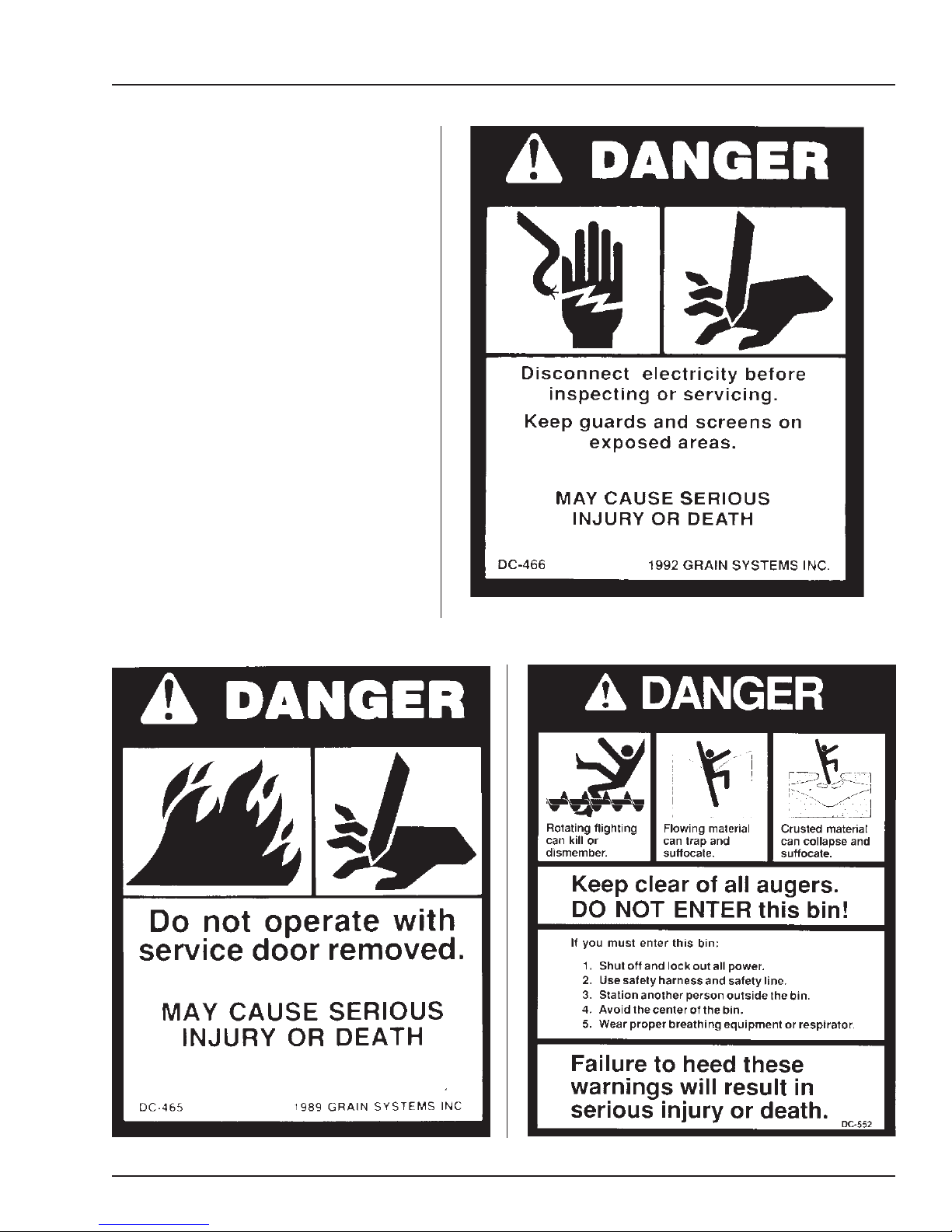
WARNING! BE ALERT!
Personnel operating or working
around electric fans should read this
manual. This manual must be
delivered with the equipment to its
owner. Failure to read this manual
and its safety instructions is a misuse
of the equipment.
The symbol shown is used to call
yourattentiontoinstructionscon-
cerning your personal safety.
Watch for this symbol; it points
out important safety precautions.
It means "ATTENTION",
"WARNING", "CAUTION",and
"DANGER". Read the message
and be cautious to the possibil-
ity of personal injury or death.
SAFETY ALERT SYMBOL
ThankyouforchoosingaGSI product. It is designed
to give excellent performance and service for many
years.
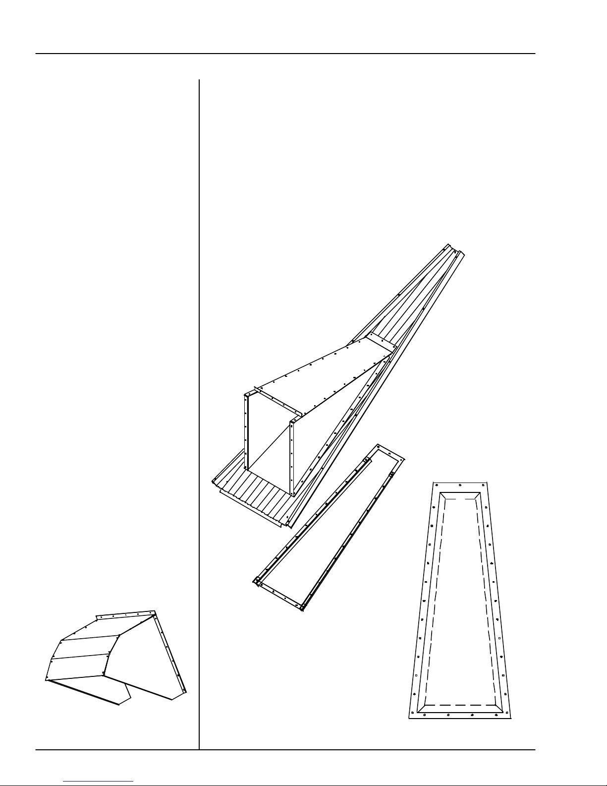
This manual describes the operation of the GSI
Roof Exhaust Fan. It is designed to take in-bin air
and expel it to the outside.
The principal concern of the GSI Group, Inc.
("GSI") is your safety and the safety of others as-
sociated with grain handling equipment. This
y to know what requirements, hazards and precau-
tions exist, and to inform all personnel associated
with the equipment, or who are in the area. Avoid
any alterations to the equipment. Such alterations
may produce a very dangerous situation, where se-
rious injury or death may occur.
GSI DOES NOT WARRANT ANY ROOF DAMAGE
CAUSED BYEXCESSIVE VACUUM OR INTERNAL
PRESSURE FROM FANS OR OTHER AIR MOVING
SYSTEMS. ADEQUATE VENTILATION AND/OR
"MAKEUP AIR" DEVICES SHOULD BE PROVIDED
FOR ALL POWERED AIR HANDLING SYSTEMS.
GSIDOESNOTRECOMMENDTHEUSEOFDOWN-
WARD FLOWSYSTEMS(SUCTION). SEVERE ROOF
DAMAGE CAN RESULT FROM ANY BLOCKAGE
OFAIRPASSAGES.RUNNINGFANSDURINGHIGH
HUMIDITY/COLD WEATHER CONDITIONS CAN
CAUSE AIR EXHAUST OR INTAKE PORTS TO
FREEZE.
ROOF EXHAUSTER FAN OPERATION
manual is written to help you understand safe oper-
atingprocedures,andsomeofthe problems that may
be encountered by the operator or other personnel.
Asownerand/oroperator,itisyour responsibilit-

5
Roof Exhaust Fan SAFETY ALERT DECALS
The GSI Group, Inc. recommends
contacting your local power company,
andhavingarepresentativesurveyyour
installationsothewiringiscompatible
with their system, and adequate power
is supplied to your unit.
Safety decals should be read and
understood by all people in the grain
handling area. The bottom right de-
cal should be present on the inside
bin door cover of the two ring door,
24" porthole door cover and the roof
manway cover.
If a decal is damaged or is miss-
ing contact:
The GSI Group, Inc.
1004 E. Illinois St.
Assumption, IL 62510
217-226-4421
A free replacement will be sent to you.

6
Roof Exhaust Fan
PRE INSTALLATION
Your model package should con-
tain items shown in the chart at
the left. Note: Before starting the
assembly and installation of the
roof exhaust fan, check to see that
all items called out on the pack-
ing list have been received. In
case there are any shortages, con-
tact your dealer. If there is any
damage during shipment, file a
claim with the carrier.
Fill in the information here for
your records. If you have a
question regarding your roof
exhaust fan, contact the dealer
from whom you purchased the
unit. If he is unable to answer
your question, refer to the fac-
tory. This information must be
available before contacting the
dealer or factory, if service is
ever needed.
SERVICE INFORMATION
An 18" roof exhaust fan.
Fanmodelnumber_________________________________________
Fanserialnumber__________________________________________
Bindiameter______________________________________________
Graintype________________________________________________
Graindepth_______________________________________________
Linevoltage(measured)_____________________________________
Dealerpurchasedfrom______________________________________
Datepurchased____________________________________________
18" Roof Fan Package 24" Roof Fan Package
Roof fan assembly Roof fan assembly
Bottom mounting flange Manual PNEG-524
Hardware package Fan housing top plate
Manual PNEG-524 Adaptor-top,right & left side
Rainhood
top, right & left side
Hardware package
(4) Template parts

7
Roof Exhaust Fan SPECIFICATIONS
Fan Model Specifications For Roof Fans
Figure 2: Open area dimensions and 24" 2 H. P. roof
fan exhauster sideview illustration.
Figure 1: Open area dimensions and 18" .5 H. P. roof
fan exhauster sideview illustration.
All single phase motors and the .5 H. P. explo-
sion proof three phase motor are supplied with au-
tomatic overload protection. The remaining three
phase motors do not have internal motor protection.
Motors rated as explosion proof (EX PRF) meet
class II group F & G of the National Electric Code
(NEC).
24.375"
24.75"
100"
58.5"
30"
50.5"
8.0"
18.0"
38.5"
18.7/16"
36.7/8"
Motor Phase &
Voltage
single-115/230V
three-230V
three-460V
single-230V
three-230
three-460V
single-115/230V
three-230
three-460V
single-115/230V
three-230
three-460V
Fan model
number
MIS-6685-1
MIS-6685-3
MIS-6685-4
MIS-6685-1E
MIS-6685-3E
MIS-6685-4E
MIS-6675-1
MIS-6675-3
MIS-6675-4
MIS-6675-1E
MIS-6675-3E
MIS-6675-4E
Fan H. P.
.5
.5
.5
.5
.5
.5
2
2
2
2
2
2
Unit
Amperage
Max.
7.2/3.6
1.8
.9
4.0
2.0
1.0
18.6/9.3
8.2
4.1
18.6/9.3
8.2
4.1
Motor Type
TEAO
TEAO
TEAO
EX PRF
EX PRF
EX PRF
TEAO
TEAO
TEAO
EX PRF
EX PRF
EX PRF
R. P. M.
1750
1750
1750
1750
1750
1750
1750
1750
1750
1750
1750
1750
Blade
Diameter
18"
18"
18"
18"
18"
18"
24"
24"
24"
24"
24"
24"

8
Roof Exhaust Fan
INSTALLATION
Standard electrical safety prac-
tices and codes should be used
when working with a fan. Refer
to the National Electric Code
Standard Handbook by the Na-
tional Fire Protection Associa-
tion. A qualified electrician
should make all wiring installa-
tions.
ALWAYS DISCONNECT
AND LOCK OUT POWER
BEFORE WORKING ON
OR AROUND FAN
18" And 24" Roof Fan Location
The roof fans should be equally spaced on the bin roof circumfer-
ence. When installed, the roof fan should be positioned as far up
the roof slope as the tapered ribs of the bin roof sheet will allow.
The rooffan location should beselected to provide a rigidmount-
ing for the fan. For bins with an innerroof structure, the roof fan
should be anchored to the inner roof structure.
Figure 4: The 18" roof exhauster fan in relation to the roof sheet.
Figure 3: The 18" template location on the roof sheet (left), and the caulking
location on the roof sheet (right).
Roof Fan Description
GSI roof exhaust fans are de-
signed to mount on structures
with sloping roofs, and with a
flat roof surface at least as large
as illustrated in Figures 1 and
2. The fans will mount between
the ribs of standard tapered roof
sheets on round steel bins with-
out cutting the ribs, which keeps
the strength of the roof sheet
intact. The 18" .5 H. P. roof fan
is shipped completely as-
sembled, and will mount on a
roof slope of 30 degrees. The
24", 2 H. P. roof fan is shipped
with the roof adaptor and
rainhood unassembled, and it is
also designed to mount on a 30
degree roof slope.
1/4" minimum
caulking
Material to anchor
roof fan to roof
structure is not
provided by The GSI
Group Inc.

9
Roof Exhaust Fan INSTALLATION
18" Roof Fan Mounting
The roof fan can be installed in the roof
sheet before assembling the roof, or af-
ter the roof is assembled. Locate roof
fan so that inner roof structure does
notinterferewith installation.Thefan
issecuredbyboltsthatmustbefastened
from the inside of the bin roof, and
therefore the assembly should be made
before the side walls are erected.
1. Using the loose flange from the fan
assembly as a template, position the
desiredrooffanlocation,allowingfor
1" minimum between the roof sheet
rib and the flange. See figure 3.
Mark the sixteen(16), 3/8" mounting
holes, and elliptical fan mounting
hole.
2. Drill the sixteen(16), 3/8" holes and
cut out the elliptical hole. Use the
caulk provided, which is specified as
a seal for metal sheets in an outdoor
application, and apply along the in
side edge of the drilled holes on the
bin roof sheet. See figure 3.
3. Place the roof fan into the elliptical
holefromtheoutsideof theroofsheet
inward. On the side of the roof sheet
thatwillbeinsidethebin,positionthe
loose mounting flange over the fan
tube. Using the sixteen (16)5/16" x
3/4" bin bolts with the neoprene
washerhead to the outside of the bin,
secure the fan, roof sheet and flange
with the 5/16" nuts provided. See
figure 4.
Figure 6: 24" roof fan adaptor and template parts breakdown.
Figure 5: 24" roof fan template placement on the roof sheet.
MIS-6706
MIS-6703
MIS-6707
When you lay out the
template for drilling
holes in the roof
sheet, be sure to
leave at least 1/4" Line for template
MIS-6664
MIS-6668
MIS-6665
MIS-6707
MIS-6706
MIS-6703
MIS-6703, MIS-6706
and MIS-6707 are
MIS-6664, MIS-6665
and MIS-6668 are
1" minimum

10
Roof Exhaust Fan
INSTALLATION
The roof fans, adaptor and
rainhood can be installed in the
bin roof sheet before assem-
bling the roof or after the roof
is assembled. The fan is se-
cured by bolts that must be fas-
tened from the inside of the bin
roof, so the assembly should be
made before the sidewalls are
erected.
1. Assemble the roof sheet
mounting template as shown
in figure 5.
2. Place the roof sheet adaptor
mounting template at the
appropriate location of the roof
fan. Move the template as far
up the roof sheet as possible,
but allow for 1" minimum
clearance between the roof
sheet rib and bottom of the tem
plate on each side.
3. Drill two corner holes and
bolt template in place.
4. Drill the remaining 11/32"
mounting holes identified on
the template.
24"RoofFanMounting
And Assembly Of Fan,
Adaptor And Rainhood
Figure 7: The rainhood
preassembly.
5. Mark a cutting line 3/4" inside the template. Then remove tem-
plate. Drill through the mark, cutting a hole in the roof sheet.
See figure 8.
6. Preassemble the adaptor section parts of the roof fan. Loosely
bolt the adaptor left side and right side to adaptor top. On all
components, bolts are to be installed with the head on the fan hous-
ing exterior.
7. Caulk along the bolt hole line where the adaptor flange will mount
to the roof sheet.
Figure 9: The 24" roof fan
adaptor on roof sheet with
template bolting underneath.
Figure 8: The cutline for roof sheet adapter.

11
Roof Exhaust Fan INSTALLATION
11. Bolt the fan housing to the adaptor. See figure
10.
12. At this time the optional 90° deflector may be
preassembled.
13. Bolt deflector assembly to MIS6674
sub- assembly for noise deflec-
tion. See figure 11.
14. Bolt rainhood to fan housing or optional 90°
deflector if installed.
15. Support optional 90° deflector adequately down
to bin roof structure to prevent exhauster or
16. The roof fan location should be selected to
provide a rigid mounting for the fan. For
bins with an inner roof structure, the roof fan
should be anchored to the inner roof structure.
17. The fan housing top plate is provided for ac-
cess to the motor for electrical installation, and
a knock out is provided in the fanside for the
wire access. Depending on when you have your
electric connections made, the motor could be
wired before step 12, or the fan could be wired
later by removing the fan housing top plate.
8. Bolt the adaptor sec-
tion to the roof sheet
along with the support
angles MIS-6703
(template)under the
roof sheet, See figure
9. Tighten the adaptor
to the roof sheet with
template bolts.
9. Form a lip up around
the inside of the adap-
tor opening by peen-
ing up the edge of the
roof sheet extending
past the inner edge of
the roof adaptor.
10.Loosely bolt the
rainhood top plate,
rainhood right side
and rainhood left side
together.
MIS-6664
Topplate
Figure 10: The 24" roof fan exhauster and rainhood.
MIS-6665
Rightside
MIS-6674
Subassembly
MIS-6666
Left side
MIS-6717
MIS-6720
Figure 11: The 24" roof fan exhauster with optional 90° deflector.
MIS-6718
Top
MIS-6719
Bottom
roof damage due to flexure of deflector and ex
hauster.
24" Roof Fan Monting and
Assembly of Fan, Adaptor
and Rainhood, continued

12
Roof Exhaust Fan
1. Reference page 10 for the 24" roof adaptor
template and mounting, and the 30° Roof
Manual PNEG-030 for the roof channel assembly.
2. Install the roof support channels in the ribs of the
upper panel where the exhauster is to be mounted.
3. Install the template and cut exhauster parts as
specified on page 10.
4. Utilize the upper MIS-6811 and lower MIS-6805
reinforcement supports to support the exhauster.
Mount reinforcement under the top support plate
MIS-6706 and bottom support plate MIS-6707
on the bottom surface of the roof panel.
5. After placing the supports, field drill the attach-
ment clip at the required locations in channels
CRP-4793.
6. Some field cutting or bolting of components may
be necessary due to variables in the roof exhauster
mounting equipment.
MIS-6706
Top Support Plate MIS-6703 (2)
Support Angles
MIS-6707
Bottom Support Plate
CRP-4793
Roof Channel
MIS-6811
Upper Reinforcement
MIS-6810 (4)
Clip For Reinforcement
MIS-6805
Lower Reinforcement
7. The MIS-6804 is designed primarily around
mounting into the upper roof of a GSI commercial
bin/silo. Field fabrication of supports may be
necessary in other brands of bins/silos.
8. A pair of adjustable brace assemblies are in-
cluded in this kit to brace the exhauster unit to the
roof ribs on the upper side of the roof. Attach the
brace to the roof exhauster unit and then attach
the other end to a roof rib (via a 5/16" bolt). This
should attach to the exhauster near the rainhood
mounting angle point.
9. The adjustable brace consists of one center
tube (LS-6615) and two end tubes (LS-6616).
The end tubes go inside the center tube and
attach one end tube to the top of the extension
rail. Adjust the other end tube so the bottom of
the flattened tube reaches the roof rib. Field
drill four 5/16" holes through both center and
end tubes and bolt together using 1/4" x 1.1/2"
bolts and nuts. This will keep the adjustable
brace from slipping.
24" ROOF EXHAUSTER REINFORCEMENT KIT
MIS-6804 24" Roof Exhauster
Reinforcement Kit Detail

13
Roof Exhaust Fan INSTALLATION
18" ROOF EXHAUSTER PARTS
Figure 12: 18" roof exhauster parts breakdown.
Reference
Number
1
2
3
4
5
6
7
8
9
Part
Number
F-942
FH-4429-1
F-6864
MIS-6680
F-6701
F-953
MIS-6689
MIS-6688
MIS-6679
Description
Control box lid
Lid clamp
Control box wrapper
18" exhauster weldment
Motor support bracket
Fan grill guard
18" fan blade
.5 H. P. motor
Mounting Flange
Quantity
1
2
1
1
1
1
1
1
1
1
2
3
4
8
7
6
59

14
Roof Exhaust Fan
INSTALLATION
24" ROOF EXHAUSTER PARTS
Reference
Number
1
2
3
4
5
6
7
8
9
10
11
12
13
14
15
16
17
18
19
20
Part
Number
MIS-6664
MIS-6666
MIS-6665
MIS-6686
MIS-6660
MIS-6706
MIS-6703
MIS-6707
MIS-6671
MIS-6672
MIS-6670
MIS-6687
TFH-2016
F-954
MIS-6662
MIS-6667
MIS-6668
MIS-6669
MIS-6659
MIS-6663
Description
Adaptor top plate
Exhauster adaptor left panel
Exhauster adaptor right panel
2 H. P. motor
Exhauster housing right side
Top support plate
Support angles
Bottom support plate
Motor support plate
Motor support channels
Support plate
24" fan blade
Venturi
Fan grill guard
Venturi mounting plate
Weather hood right panel
Weather hood left panel
Weather hood top
Exhauster housing left side
Exhauster housing top plate
Quantity
1
1
1
1
1
1
2
1
1
2
1
1
1
1
1
1
1
1
1
1
1
2
3
4
56
7
8
9
1011
12
13
14
15
16
17
18
19
20

15
Roof Exhaust Fan ELECTRICAL INSTALLATION
7 entiled "Fan Model Specifications" indicates the
electrical service the fan is designed to utilize in the
column labeled "Motor PhaseandVoltage". Theelec-
trical service must match this specification.
The components to connect the electrical ser-
1. Transformer
The transformer size for the fan only is indi-
cated in a KVArating. Example: For a 24"
fan the first chart would be used. The KVA
rating for the 2 horse power motor
is 3.5 KVA. This KVA rating is for
the fan only. Your electrician will need
to add the KVA requirements for the other
electrical components of the system in sizing
the transformer.
Electrical Installation Of The Fan
The electrical installation must be performed by a
certified electrician in accordance with the appro-
priate national and local electrical codes.
CAUTION! ANYVIOLATION OF ELECTRICAL
WIRING CODES COULD JEOPARDIZE THE
AIRSTREAM WARRANTY.
Check the type of electrical service present, and
make sure the fan to be wired is manufactured to
op-erate on the electrical service. The table on page
vice to the fan need to be sized for the electrical
service present. The charts below illustrate the siz-
ing information for single phase 230 volt, three
phase 230 volt and 460 volt respectively. Use the
appropriate information and size the following electrical
service components:
Electrical Service For Three Phase Operation 460 Volt
0.5
2.0
Motor
H. P.
Range
Transformer Size
(Note B) (Minimum) Copper Wire Size for Distance-Motor to
Disconnect in Feet up to: Fusetron or
Equivalent Time
Delay Fuse AMP
1.0 KVA
3.5 KVA
0'-50' 100' 200' 300'
14
14 14
14 14
12 14
12 10
10
Electrical Service For Three Phase Operation 230 Volt
0.5
2.0
Motor
H. P.
Range
Transformer Size
(Note B) (Minimum) Copper Wire Size for Distance-Motor to
Disconnect in Feet up to: Fusetron or
Equivalent Time
Delay Fuse AMP
1.0 KVA
3.5 KVA
0'-50' 100' 200' 300'
14
14 14
12 14
10 14
810
15
Electrical Service For Single Phase Operation 230 Volt
0.5
2.0
Motor
H. P.
Range
Transformer Size
(Note B) (Minimum) Copper Wire Size for Distance-Motor to
Disconnect in Feet up to: Fusetron or
Equivalent Time
Delay Fuse AMP
1.0 KVA
3.5 KVA
0'-50' 100' 200' 300'
14
12 14
10 12
610
510
30

16
Roof Exhaust Fan
ELECTRICAL INSTALLATION
2. Fan Disconnect
A disconnect for the fan needs to
be sized to handle the recom-
mended fusetron size. Example:
For a 24" fan the first chart on
page 14 would be used, and the
fusetron size is 30 AMP. Install
the fusetron recommended in the
disconnect. A circuit breaker can
be used, however, the circuit
breaker or any fuse used must be
a time delay type to allow the ini-
tial starting inrush current to the
fan.
3. Conductor size for the fan
disconnect to fan wiring
The conductor size for the fan
needs to be sized according to
the distance between the fan
and disconnect. Example:
For a 24" fan located 200'
from the disconnect use the
first chart on page 14 to de-
termine the conductor size to
be a 14 AWG. The proper size
wiring must be used to make
sure a voltage drop does not
occur.
4. Fan Motor Controller
Size the fan motor controller ac-
cording to the motor ratings for a
convenient control location as fol-
lows:
Motorswithinternaloverload
protectionwillrequireamag-
netic contactor to control fan
operation.
Figure 14: Correcting the fan rotation for three phase.
three phase power. The four wires consist of three current carry-
ing conductors, and a ground. The current carrying conductors
are wired per the diagram on the motor. The ground is se-
cured to the motor frame. On 2 H.P. explosion proof mo-
tors thermostat wires are provided with the motor, and must
be connected to the fan motor magnetic con-
trols.
When installing electrical service for explosion proof motors make
sure all conduit and connectors exposed to the conditions of the
motor are rated for the Class II group F and G location of the mo-
tor.
5. Single Phase
A 3-wire system should be provided for fans to be operated
on single phase power. The three wires consist of the two
current conductors and aground. The current carrying conduc-
tors are wired per the diagram on the motor. The ground is
secured to the motor frame. On 2 H.P. explosion proof motors
thermostat wires are provided with the motor, and must be con-
nected to the fan motor magnetic controls.
6. Three Phase
A 4-wire system should be provided for fans to be operated on
Motors without overload protection will require a magnetic starter
with overload protection to control fan operation.

17
Roof Exhaust Fan ELECTRICAL INSTALLATION
Installation Check
Transformer size is based on the current
draw from the fan only. Your electrician will
need to add the KVA requirements for the
other components of the system in sizing the
transformer.
Copper wire (rated 75°F) is sized for the
fan service. The wire size from the trans
former to the disconnect service will be de-
termined from the fan, and the other elec-
trical equipment requirements.
2. Three Phase System
With the power OFF at the fan disconnect, ex
change the location of the current carrying con-
Whenthefaniscompletelyassembled and wired the unit
needstobecheckedforproperrotation. Providepowerto
thefancontrols and startthefanmomentarily. Makesure
the fan blade rotates to exhaust air from the bin. If the
blade is rotating the wrong direction, have your electri-
cian correct as follows:
1. Single Phase System
With the power OFF at the fan disconnect, the
motor lead wires at the fan motor need to change
as indicated on the motor to reverse the blade rota
tion. The unit then needs to be rechecked for
properrotation.
24" roof fan exhauster with the rainhood in place.
ductors at terminal L1 and L3 (figure 14) of the
magnetic controls. The unit will then need to
be rechecked for proper rotation.
Always check current local, state and national
codes on electrical requirements before install
ing any electrical equipment.

18
Roof Exhaust Fan
OPERATING INSTRUCTIONS
Before Starting Fan
When shutting the fan down for the season, shut off
the power at the fan disconnect rather than at the fan
controls to provide additional protection from unau-
thorizedpersonneloperatingthefan,andpotentialdam-
age to the fan from a lightning strike.
Starting The Fan
Fan Shut Off
Theroofexhaust fans should operateanytimethe
supply fans operate. The roof fans can operate
independently of the supply fans just to provideven-
tilation of the attic space, but this requires that vents be
used in the roof to provide an open area.
18" fan............4 square feet per fan
24" fan...........10 square feet per fan
When starting the fan for the first time, check the
following:
1. WiththepowerOFF,rotatethe fan blade to make
sure it revolves easily, and does not rub on the
venturi or fan tube.
2. Check all the fasteners to make sure they are
tight. If any are loose, check for proper clear-
ance and retighten.
3. With the power OFF, check all electrical con-
nections to make sure they are tight. Inspect
the current carrying wires to make sure they are
not grounded. Make sure the fan and disconnect
are grounded. All control enclosure covers and
ac- cess doors should be secured in place.
4. Refer to the wiring diagram on the motor, and
make sure the motor is wired correctly. When servicing the fan, switch power OFF at the
fan disconnect switch. Activate power only when a
check is made. The following items will help you
to pinpoint a possible malfunction of the fan unit
and explain the corrective action to take.
Ifthemotorcontrolleristurnedonand noth-
ing happens, check the following:
1. Make sure power is available to the fan unit.
2. Check the motor thermostat (if present) to de
termine if the thermostat is open or closed. If
the thermostat is open, take the motor to your
local authorized service center. When check-
ing the thermostat, make sure the motor has time
to cool, if hot.
Fan Service
Duringtheoffseason, the fanbladeshould beallowed
to turn freely. The fan should operate for approxi-
mately 30 minutes every three weeks. This keeps the
fan lubricant more evenly distributed within the bear-
ing cavity, and dries out any condensation that could
be in the motor.
Off Season Operation And Maintenance

19
Roof Exhaust Fan
thorized motor service center for repair or re
placement.
If the fan just hums when turned on, check the
following:
1. Check to make sure that all leads of your power
source have voltage present. If fan unit is not
receiving power on all leads, check for a blown
fuse, broken wire or loose connection.
2. Check to see that all contact sets are closing. If
one leg of the supply voltage is not available
to the motor it will hum.
3. If power is available at all motor leads, and the
motor still hums, it should be taken to an autho-
3. If power is available to the motor and it does
not run, remove the motor and take it to an au- rized service center for repair or replacement.
If the fan starts and operates for awhile and then
shuts off, check the following:
1. Check the supply voltage. Voltage should be
within +/-10% of rated voltage. For example,
a motor rated at 230 volt should operate in a
voltage range of 207 to 253 volt.
2. Check the supply wire size required for the fan
unit.
3. Check the load on the main circuit to make sure other
items on it are not overloading the fan circuit.
4. Check the amperage of the fan, if the unit is
pulling above name plate amperage, take the
motor to an authorized service center.
OPERATING INSTRUCTIONS

20
Roof Exhaust Fan
WARRANTY
EXCEPTFOR THEABOVE STATED EXPRESS LIMITED WARRANTIES, GSI MAKES NO WARRANTY OF
ANY KIND, EXPRESSED OR IMPLIED, INCLUDING, WITHOUT LIMITATION, WARRANTIES OF MER-
CHANTABILITYOR FITNESS FORAPARTICULAR PURPOSE OR USE IN CONNECTION WITH (i) PROD-
UCT MANUFACTURED OR SOLD BY GSI OR (ii) ANY ADVICE, INSTRUCTION, RECOMMENDATION
OR SUGGESTION PROVIDED BYANAGENT, REPRESENTATIVE OR EMPLOYEE OF GSI REGARDING OR
RELATED TO THE CONFIGURATION, INSTALLATION, LAYOUT, SUITABILITY FOR A PARTICULAR
PURPOSE, OR DESIGN OF SUCH PRODUCT OR PRODUCTS.
IN NO EVENT SHALLGSI BE LIABLE FORANY DIRECT, INDIRECT, INCIDENTALOR CONSEQUEN-
TIALDAMAGES, INCLUDING, WITHOUTLIMITATION, LOSS OFANTICIPATED PROFITS OR BENEFITS.
PURCHASER'S SOLEAND EXCLUSIVEREMEDYSHALLBE LIMITEDTOTHAT STATEDABOVE, WHICH
SHALL NOT EXCEED THE AMOUNT PAID FOR THE PRODUCT PURCHASED. THIS WARRANTY IS
NOT TRANSFERABLE AND APPLIES ONLY TO THE ORIGINAL PURCHASER. GSI SHALL HAVE NO
OBLIGATION OR RESPONSIBILITY FOR ANY REPRESENTATIVE OR WARRANTIES MADE BY OR ON
BEHALF OF ANY DEALER, AGENT OR DISTRIBUTOR OF GSI.
GSIASSUMES NO RESPONSIBILITYFOR FIELD MODIFICATIONS OR ERECTION DEFECTS WHICH
CREATE STRUCTURAL OR STORAGE QUALITYPROBLEMS. MODIFICATIONS TO THE PRODUCTNOT
SPECIFICALLY COVERED BY THE CONTENTS OF THIS MANUAL WILL NULLIFY ANY PRODUCT
WARRANTY THAT MIGHT HAVE BEEN OTHERWISE AVAILABLE.
THE FOREGOING WARRANTY SHALL NOT COVER PRODUCTS OR PARTS WHICH HAVE BEEN
DAMAGED BY NEGLIGENT USE, MISUSE, ALTERATION OR ACCIDENT. THIS WARRANTY COVERS
ONLY PRODUCTS MANUFACTURED BY GSI. THIS WARRANTY IS EXCLUSIVE AND IN LIEU OF ALL
OTHER WARRANTIES EXPRESS OR IMPLIED. GSI RESERVES THE RIGHTTO MAKE DESIGN OR SPECI-
FICATION CHANGES AT ANY TIME.
PRIORTO INSTALLATION, PURCHASER HAS THE RESPONSIBILITYTO RESEARCHAND COMPLY
WITH ALL FEDERAL, STATE AND LOCAL CODES WHICH MAY APPLY TO THE LOCATION AND IN-
STALLATION.
THE GSI GROUP, INC. ("GSI") WARRANTSALLPRODUCTS MANUFACTURED BYGSI TO BE FREE
OF DEFECTS IN MATERIAL AND WORKMANSHIP UNDER NORMAL USAGE AND CONDITIONS
FOR A PERIOD OF 12 MONTHS AFTER RETAIL SALE TO THE ORIGINAL END USER OF SUCH
PRODUCTS. GSI'S ONLY OBLIGATION IS, AND PURCHASER'S SOLE REMEDY SHALL BE FOR
GSI, TO REPAIR OR REPLACE,AT GSI'S OPTIONAND EXPENSE, PRODUCTSTHAT, IN GSI'S SOLE
JUDGMENT, CONTAIN A MATERIAL DEFECT DUE TO MATERIALS OR WORKMANSHIP. ALL
DELIVERY AND SHIPMENT CHARGES TO AND FROM GSI'S FACTORY WILL BE PURCHASER'S
RESPONSIBILITY. EXPENSES INCURRED BY OR ON BEHALF OF THE PURCHASER WITHOUT
PRIOR WRITTEN AUTHORIZATION FROM AN AUTHORIZED EMPLOYEE OF GSI SHALL BE THE
SOLE RESPONSIBILITY OF THE PURCHASER.
Table of contents
Other GSi Fan manuals
Popular Fan manuals by other brands

TaoTronics
TaoTronics TT-TF005 user manual

Ebmpapst
Ebmpapst W4E400-CP02-31 operating instructions

Klarstein
Klarstein 10027944 manual

Schwille Elektronik
Schwille Elektronik Dew Point Touch 100-600 operating instructions

Maico
Maico ECA 120 SERIES Mounting and operating instructions

Goldair
Goldair GCHV210 operating instructions

Ebmpapst
Ebmpapst K3G250-BB09-S1 operating instructions

Regency Ceiling Fans
Regency Ceiling Fans CABANA owner's guide

Ellington
Ellington Metron MET56BNK4 installation guide

Johnson Controls
Johnson Controls tyco TAV-D manual

S&P
S&P TPSB ECOWATT Series instruction manual

Soleus Air
Soleus Air FTM-25 owner's manual