GSi PNEG-163-04 Owner's manual

Centrifugal Fan
Installation and Operation
Owner’s Manual
PNEG-163-04
Date: 11-26-07
PNEG-163-04

2 PNEG-163-04 Centrigual Fan
1. All wire connections
2. Tip clearance on blade
3. Fan blade torqued to torque specs
4. Grill guard in place and tight
5. Fuse in place, extra fuse provided
6. Motor rotation correct
7. Contactor engages properly
8. Running amperage
9. Vibration
10. All fasteners tight
11. Indicator light
12. All decals and serial number tag
13. Aesthetic appearance
14. Manual
15. Manual Supplements for Double Inlet Fans
Model #:
Serial #:
Tester Signature:
Date:

PNEG-163-04 Centrifugal Fan 3
Table of Contents
Contents
Chapter 1 Safety .................................................................................................................................. 5
Safety Guidelines ................................................................................................................ 5
Safety Decals ...................................................................................................................... 8
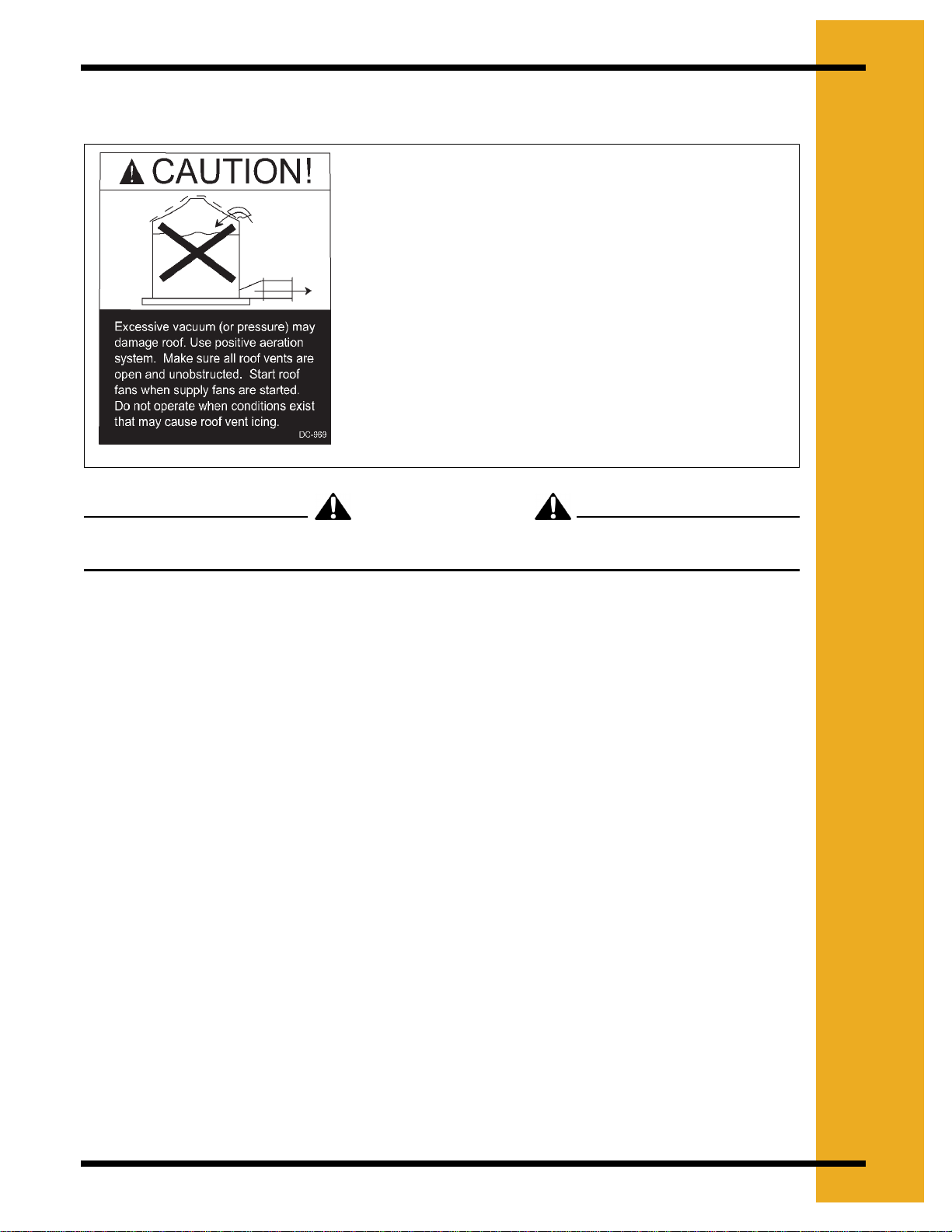
Roof Damage Warning and Disclaimer ............................................................................... 9
Chapter 2 Installation ....................................................................................................................... 10
Pre-Installation Requirements ........................................................................................... 10
Fan Installation .................................................................................................................. 11
Electrical Installation ......................................................................................................... 11
Test Run ............................................................................................................................ 12
Ground Rod Installation .................................................................................................... 13
Chapter 3 Fan Specifications ........................................................................................................... 14
1750 rpm Fan Electrical Specifications ............................................................................. 14
3500 rpm Fan Electrical Specifications ............................................................................. 15
Fan Dimensions ................................................................................................................ 16
Discharge Bolt Pattern Dimensions .................................................................................. 17
Inlet Cone Dimensions ...................................................................................................... 18
Fan Wheel Dimensions ..................................................................................................... 19
Fan Pad Location .............................................................................................................. 20
Chapter 4 Operation ......................................................................................................................... 21
Fan Start-Up ...................................................................................................................... 21
Fan Shut-Down ................................................................................................................. 21
Maintaining Grain Quality .................................................................................................. 21
Grain Storage .................................................................................................................... 22
Chapter 5 Maintenance and Troubleshooting ................................................................................ 23
Fan Wheel Removal & Installation .................................................................................... 23
Fan Wheel Inspection & Maintenance .............................................................................. 24
Taper Bushing Torque Requirements ............................................................................... 25
Fan Motor Removal & Installation ..................................................................................... 25
General Inspection ............................................................................................................ 25
Lubrication & Bearings ...................................................................................................... 26
Troubleshooting Charts ..................................................................................................... 27
Chapter 6 Parts ................................................................................................................................. 29
Main Assembly - 1750 rpm Fans ...................................................................................... 30
Main Assembly - 3500 rpm Fans ...................................................................................... 35
Main Assembly - Single Inlet Direct Drive Fan .................................................................. 40
Main Assembly - Double Inlet Fan .................................................................................... 41
Internal Bearing Arch Assembly - Double Inlet Fan .......................................................... 42
Motor Drives - Double Inlet Fan ........................................................................................ 43
Shaft Coupling ................................................................................................................... 44
Control Box Sub - Assembly ............................................................................................. 45
Control Box Assembly - Single Phase 230 Volt ................................................................ 46
Control Box Assembly - Three Phase 230 Volt ................................................................. 47
Control Box Assembly - Three Phase 460 Volt ................................................................. 51
Motor Conduit Assembly ................................................................................................... 56

4 PNEG-163-04 Centrifugal Fan
Table of Contents
Chapter 7 Schematics / Wiring Diagrams .......................................................................................62
Wiring Schematic - 230 Volt 1 Phase ................................................................................62
Wiring Diagram - CF-3-1C .................................................................................................63
Wiring Schematic - 230 Volt 1 Phase ................................................................................64
Wiring Diagram - CHS-3-1C ..............................................................................................65
Wiring Schematic - 230 Volt 1 Phase ................................................................................66
Wiring Diagram - CF-5-1C, CF-7.5-1C, CHS-5-1C & CHS-7.5-1C ...................................67
Wiring Schematic - 230 Volt 1 Phase ................................................................................68
Wiring Diagram - CF-10-1C & CHS-10-1C ........................................................................ 69
Wiring Schematic - 230 Volt 1 Phase ................................................................................70
Wiring Diagram - CF-15-1C ............................................................................................... 71
Wiring Schematic - 230 Volt 3 Phase ................................................................................72
Wiring Diagram - 230 Volt 3 Phase ...................................................................................73
Wiring Schematic - 460 Volt 3 Phase ................................................................................74
Wiring Diagram - 460 Volt 3 Phase ...................................................................................75
Chapter 8 Appendix A........................................................................................................................76
Chapter 9 Warranty ............................................................................................................................77

PNEG-163-04 Centrifugal Fan 5
1.SAFETY
Safety Guidelines
This manual contains information that is important for you, the owner/operator, to know and
understand. This information relates to protecting personal safety and preventing equipment
problems. It is the responsibility of the owner/operator to inform anyone operating or working in
the area of this equipment of these safety guidelines. To help you recognize this information, we
use the symbols that are defined below. Please read the manual and pay attention to these
sections. Failure to read this manual and it’s safety instructions is a misuse of the equipment and
may lead to serious injury or death.
DANGER
WARNING
CAUTION
CAUTION
NOTE
This is the safety alert symbol. It is used to alert you
to potential personal injury hazards. Obey all safety
messages that follow this symbol to avoid possible
injury or death.
DANGER indicates an imminently hazardous situation
which, if not avoided, will result in death or serious
injury.
WARNING indicates a potentially hazardous situation
which, if not avoided, could result in death or serious
injury.
CAUTION indicates a potentially hazardous situation
which, if not avoided, may result in minor or moderate
injury.
CAUTION used without the safety alert symbol indicates
a potentially hazardous situation which, if not avoided,
may result in property damage.
NOTE indicates information about the equipment that
you should pay special attention to.

6 PNEG-163-04 Centrifugal Fan
1. SAFETY
Follow Safety Instructions
Carefully read all safety messages in this manual and
safety signs on your equipment. Keep signs in good
condition. Replace missing or damaged safety signs.
Be sure new equipment components and repair parts
include the current safety signs. Replacement safety
signs are available from the manufacturer.
Learn how to operate the machine and how to use
controls properly. Do not let anyone operate without
instruction.
Keep your machinery in proper working condition.
Unauthorized modifications to the machine may
impair the function and/or safety and affect machine
life.
If you do not understand any part of this manual and
need assistance, contact your dealer.
Practice Safe Maintenance
Always lockout power source before servicing
equipment.
Understand service procedures before doing
work. Keep area clean and dry.
Never lubricate, service, or adjust machine while
it is in operation. Keep hands, feet, and clothing
from rotating belt and idlers.
Keep all parts in good condition and properly
installed. Fix damage immediately. Replace
worn or broken parts. Remove any build up of
grease, oil, or debris.
Be prepared if fire starts.
Keep a first aid kit and fire extinguisher
handy.
Keep emergency numbers for doctors,
ambulance service, hospital, and fire
department near your telephone.
Prepare for Emergencies
Keep Emergency Equipment
Quickly Accessible

PNEG-163-04 Centrifugal Fan 7
1. SAFETY
Wear Protective Clothing
Wear close fitting clothing and safety
equipment appropriate to the job.
Ear Plugs or Muffs should be worn at all
times to protect ears from high noise
levels.
Safety glasses should be worn at all times
to protect eyes from debris.
Wear gloves to protect your hands from
sharp edges on plastic or steel parts.
Wear steel toe boots to help protect your
toes from falling debris.
A respirator may be needed if a hog house
has poor ventilation. Waste fumes can be
toxic.
Remove all jewelry.
Tuck in any loose or dangling shoe strings.
Long hair should be tied up and back.
Wear hard hat to help protect your head.
Eye Protection
Gloves
Steel Toe Boots
Respirator
Hard Hat
Hearing Protection
Install & Operate Electrical Equipment Properly
Electrical controls should be installed by a qualified
electrician and must meet the standards set by the
national electrical code and all local and state codes.
Disconnect and lock out all power sources before
installing wires/cables or servicing equipment.
Install & Operate Gas-Fired Equipment Properly
Fuel supply should be installed by a qualified gas
technician and must meet local and state codes for
gaseous fuel supplies.
Disconnect and lock out all fuel sources before
servicing equipment.

8 PNEG-163-04 Centrifugal Fan
1. SAFETY
SAFETY DECALS
Safety decals should be read and understood by all people in the grain handling area.
If a decal is damaged or is missing contact:
The GSI Group, Inc.
1004 E. Illinois St.
Assumption, IL 62510
Ph:(217)-226-4421
A free replacement will be sent to you.
Operation above maximum speed will
structurally damage fan blade and void
warranty.
Do not operate fan above maximum speed.
Maximum speed: 1750 rpm
IMPORTANT
DC-1544
IMPORTANT!
To Maintain Proper Working Conditions and
Avoid Possible Failure at Harvest Time,
Operate Motor Unit for 20 Minutes Each
Month.
DC-163
Part Number: DC-1749
Size: 1.75" x 3.75"
Located on fan coupling guard on motor driven fans.
WARNING
Stay clear of rotating
blade. Blade could start
automatically. Can cause
serious injury. Disconnect
power before servicing.
DC-1225
-DC 889
Lockout power
before servicing.
HIGH VOLTAGE.
Will cause injury
or death.
Part Number: DC-1225
Size: 4.875" x 2.25"
Located on fan housing side near fan inlet.
Part Number: DC-1224
Size: 2.625" x 4.625"
Located on fan housing
side above motor &
located on outside of
control box lid.
Part Number: DC-889
Size: 2.813" x 1.375"
Located inside control box.
Part Number: DC-113
Size: 4.75" x 1.625"
Located on painted inlet cone of
fan housing.
Part Number: DC-1544
Size: 4.00" x 6.00"
Located on fan housing motor side.
Part Number: DC-163
Located on fan housing motor side.
Part Number: DC-219
Located on fan inlet cone.
AIRFLOW
AIRFLOW

PNEG-163-04 Centrifugal Fan 9
1. SAFETY
Roof Damage Warning and Disclaimer
This product has sharp edges! These sharp edges may cause serious injury. To avoid injury
handle sharp edges with caution and use proper protective clothing and equipment at all times.
General Safety Statements
Thank you for choosing a GSI Group product. It is designed to give excellent performance and
service for many years.
It is the plan of The GSI Group to improve its product whenever possible and practical to do so.
We reserve the right to change, improve, and modify products at any time without obligation to
make changes, improvements, and modifications on equipment sold previously.
The principal concern of The GSI Group Inc. (“GSI”) is your safety and the safety of others
associated with grain handling equipment. This manual is written to help you understand safe
operating procedures, and some of the problems that may be encountered by the operator or
other personnel.
As owner and/or operator, it is your responsibility to know what requirements, hazards and
precautions exist, and to inform all personnel associated with the equipment, or who are in the
dryer area. Avoid any alterations to the equipment. Such alterations may produce a very
dangerous situation, where serious injury or death may occur.
THIS MANUAL DESCRIBES THE OPERATION OF THE CENTRIFUGAL FAN. THIS
PRODUCT IS IDEAL FOR THE CONDITIONING OF CORN, SOYBEANS, AND OTHER
SELECT GRAINS. ANY OTHER USE IS CONSIDERED A MISUSE OF THE PRODUCT.
GSI DOES NOT WARRANT ANY ROOF DAMAGE
CAUSED BY EXCESSIVE VACUUM OR INTERNAL
PRESSURE FROM FANS OR OTHER AIR MOVING
SYSTEMS. ADEQUATE VENTILATION AND/OR
“MAKEUP AIR” DEVICES SHOULD BE PROVIDED
FOR ALL POWERED AIR HANDLING SYSTEMS.
GSI DOES NOT RECOMMEND THE USE OF
DOWNWARD FLOW SYSTEMS (SUCTION).
SEVERE ROOF DAMAGE CAN RESULT FROM
ANY BLOCKAGE OF AIR PASSAGES. RUNNING
FANS DURING HIGH HUMIDITY/COLD WEATHER
CONDITIONS CAN CAUSE AIR EXHAUST OR
INTAKE PORTS TO FREEZE.
CAUTION

10 PNEG-163-04 Centrifugal Fan
2. INSTALLATION
Pre-Installation Requirements
Foundation
Use the dimension illustration in the specifications section of this manual to determine the
physical size of the fan to be installed. Use the dimensions shown to determine the position of
the fan installation with respect to other equipment.
For proper operation of your fan, the unit is to be mounted on a level pad. The fan should not be
anchored to the pad, but it should be allowed to “float” on the pad.The fan pad should be offset
2.00" below the top of the bin foundation. Refer Figure 3F on Page20 in the specifications section
of this manual for recommendations of pad placement with respect to various catalog transition
ducts.
Transition
The transition duct should be all metal construction, with a gradual angle to the rectangular
opening in the bin wall. The duct should allow for a smooth transition with minimal resistance of
the airflow from the fan discharge to the bin plenum. Keep the entrance of the plenum as clear
as possible from obstructions by floor support.
Roof Exhaust
Adequate exhaust air openings in the roof are required to prevent any additional back pressure
from building in the bin. See “Roof Damage Warning” on Page 9.
Power Supply
Adequate power must be supplied to the fan for reliable operation. Consult the local power
company and have a representative survey the installation. Only the power company can ensure
that their system is sized properly to provide adequate service to the installation and new
equipment.
Wire Size
Undersized wire can lead to voltage drop which causes motor overheating and shortened motor
life. Use the electrical specifications chart in this manual to size the supply wire according to the
horsepower of the fan and the distance to the power supply. Refer to the “Fan Specifications”
on Page 14 to find the full load current of the motor for a given fan size. The full load current can
also be found on the motor nameplate.
Service Disconnect
Each fan motor must be supplied with an independent power circuit, equipped with a fused
disconnect switch. Locate this switch near the unit, as the power should be shut off before
servicing the fan.
It is the customer’s responsibility to provide a fused disconnect and motor overload protection.
These must be properly sized and connected to allow proper motor operation. Failure to provide
these components could cause severe motor damage and void the manufacturer’s warranty.

PNEG-163-04 Centrifugal Fan 11
2. INSTALLATION
Fan Installation
1. Remove packaging materials and inspect fan for any shipping damages. Report these at
once to the shipper.
2. Check all fasteners on the fan to make sure they are tight (fasteners may loosen during
shipment). Tighten any loose fasteners, check for proper clearance and retighten.
3. Check all electrical connections that may have loosened during shipment.
4. Rotate the fan wheel. Wheel should rotate freely and should not make contact with the
housing sides or inlet cone.
5. Place fan in proper location on the fan pad. Attach fan to transition duct and seal connection
with caulk.
6. Check all joints and seams around the lower part of the bin. Verify that these are well sealed
to prevent air leakage from the bin plenum. Inspect the transition duct as well. Seal any
leaks that may be present to prevent air losses that reduce fan efficiency.
7. Level fan. Fan pad should be poured flat and level, however, it may be necessary to adjust
the legs provided on the fan housing to level the fan. The legs should be adjusted so that
when level all five legs touch the pad. Fans not resting on support legs may have excess
vibration which can lead to premature wear and tear on fan components.
Always disconnect and lock out power before working on or around fan.
Important: Electrical installation must be performed by a qualified electrician, in
accordance with National and local electrical codes. Any violation of electrical
wiring codes could jeopardize the warranty.
Electrical Installation
1. Verify that the incoming power supply has been deemed adequate by the local power
company.
2. Verify that the wiring supplying power to the fan is sized correctly for the distance away from
supply and fan horsepower. (See tables in specification section on Page 14)
3. Verify that the safety disconnect is installed and sized correctly for the fan size. (See tables
in specification section on Page 14)
4. Install a machine to earth ground for each individual fan. Refer to the “Ground Rod
Installation” on Page 13.
5. The following wires must be supplied to each fan.Units without control transformers require
a separate neutral and earth ground connection.
6. The starter controls require 115VAC power to operate. On 230 Volt 3 Phase units, this
power is supplied by L1 to neutral.
1PH 230V L1, L2, N, G
3PH 230V L1, L2, L3, N, G
3PH 230V with optional transformer kit L1, L2, L3, G
3PH 460V/575V L1, L2, L3, G
DANGER

12 PNEG-163-04 Centrifugal Fan
2. INSTALLATION
The voltage between L1 and N must be 115VAC. Any other voltage will cause damage to
equipment.
Check this voltage before starting unit. If voltage is not within 105 - 125VAC, check for proper
voltage on L2 or L3 and move to appropriate leg. If voltage is not acceptable, install a 0.25 KVA
step-down transformer.
Note: Grounded B and some open delta power supplies will require this transformer kit.
Final Check
Check to make sure all safety guards are in place and not damaged. Replace damaged parts.
Check to make sure all decals are visible and not damaged. Replace damaged decals.
Check to make sure all control boxes are closed and no wiring is exposed.
Test Run
When the fan is completely installed, the unit will need to be checked for proper rotation. Provide
power to the fan controls and start the fan momentarily. Make sure that the fan wheel rotation is
in the direction that the decal on the fan housing illustrates. If the decal is missing, note that the
wheel should operate counterclockwise when viewed through the inlet guard on standard
construction fans. If the wheel is rotating the wrong direction, have your electrician correct the
wiring.
Figure 2A
CAUTION

PNEG-163-04 Centrifugal Fan 13
2. INSTALLATION
Machine to Earth Ground
It is very important that a machine to earth ground rod be installed at the fan. This is true even if
there is a ground at the pole 15 feet away. This ground needs to be as close to the fan as
possible, but no more than 8 feet away. The ground rod should be connected to the fan control
panel with at least a #6 solid bare copper ground wire, or in accordance with local requirements.
The machine to earth ground provides additional safety if there is a short. It also provides the
grounding necessary for long life and operation of the solid state circuit boards used on control
circuits and the electronic ignition systems.
Previously Installed Units
It is recommended that previously installed units be checked to see that a machine to earth
ground has been installed by an electrician.
Ground Rod Installation
Proper Installation of the Ground Rod
(Ground rods and wires are not supplied). It is recommended that the rod not be driven into dry
ground. The following steps ensure proper ground rod installation:
1. Dig a hole large enough to hold 1 to 2 gallons of water.
2. Fill hole with water.
3. Insert rod through water and jab it into the ground.
4. Continue jabbing the rod up and down, the water will work its way down the hole, making it
possible to work the rod completely into the ground. This method of installing the rod gives
a good conductive bond with the surrounding soil.
5. Connect the bare copper ground wire to the rod with the proper ground rod clamp.
6. Connect the bare ground wire to the fan control boxes with a grounding lug.
7. Ground wire must not have any breaks or splices. Insulated wire is not recommended for
grounding.
Dig a hole large enough to hold 1 or 2
gallons of water.
Work the ground rod into the earth until it
is completely in the ground.

14 PNEG-163-04 Centrifugal Fan
3. FAN SPECIFICATIONS
1750 rpm Fan Electrical Specifications
* Based on NEC Tables 430 - 148 & 430 - 150
Important: The values listed in this chart are recommendations only. Electrical
installation must be performed by a qualified electrician, in accordance with
National and local electrical codes. Any violation of electrical wiring codes
could jeopardize the warranty.
Fan
Horsepower 357.1/210
Phase 1 3 1 3 1 3 1 3
Volts 230 230 460 575 230 230 460 575 230 230 460 575 230 230 460 575
Full Load
Current (Amps) * 17 9.6 4.8 3.9 28 15.2 7.6 6.1 40 22 11 9 50 28 14 11
Minimum Wire
Size Copper Wire Copper Wire Copper Wire Copper Wire
50'Run 1214141410 14 1414 8 101414 6 101414
100' Run 12 14 14 14 8 12 14 14 8 10 14 14 6 10 14 14
200' Run 8 12 14 14 6 10 14 14 4 8 14 14 4 6 12 14
300' Run 6 10 14 14 4 8 14 14 3 6 12 14 2 4 10 12
Minimum Wire
Size Aluminum Wire Aluminum Wire Aluminum Wire Aluminum Wire
50' Run 10 12 12 12 8 12 12 12 6 10 12 12 4 8 12 12
100' Run 8 12 12 12 6 10 12 12 6 8 12 12 4 8 12 12
200' Run 6 10 12 12 4 8 12 12 3 6 12 12 2 4 10 12
300'Run 4 812123 6 12121 410120 3 810
Fuse Size
(Slow Blow) 30 15 8 6 50 25 12 10 70 40 20 15 90 45 25 20
Breaker Size 50 15 15 15 70 30 15 15 100 40 20 15 125 50 30 20
Fan
Horsepower 15 20 25 30 40 50
Phase 1 3 3 3 3 3 3
Volts 230 230 460 575 230 460 575 230 460 575 230 460 575 230 460 575 230 460 575
Full Load
Current (Amps)
*
65 42 21 17 54 27 22 68 34 27 80 40 32 104 52 41 130 65 52
Minimum Wire
Size Copper Wire Copper Wire Copper Wire Copper Wire Copper Wire Copper Wire
50' Run 4 6 10 12 4 10 10 4 8 10 3 8 8 1 6 6 00 4 6
100' Run 4 6 10 12 4 10 10 4 8 10 3 8 8 1 6 6 00 4 6
200' Run 3 4 10 12 4 10 10 3 8 10 3 8 8 1 6 6 00 4 6
300' Run 1 4 10 10 3 8 10 2 68168066 00 4 6
Minimum Wire
Size Aluminum Wire Aluminum Wire Aluminum Wire Aluminum Wire Aluminum Wire Aluminum Wire
50'Run 2 4 1010381026816800440000 2 4
100' Run 2 4 10 10 3 8 10 2 6816800440000 2 4
200' Run 1 3 8 10 2 8 10 1 6806800440000 2 4
300' Run 00 1 6 8 0 6 8 00 4 6 00 4 6 000 4 4 0000 2 4
Fuse Size
(Slow Blow) 125 70 40 30 90 45 40 110 60 45 125 60 50 175 80 70 200 100 80
Breaker Size 175 70 40 30 90 50 40 110 60 50 125 60 50 175 80 70 200 100 80

PNEG-163-04 Centrifugal Fan 15
3. FAN SPECIFICATIONS
3500 rpm Fan Electrical Specifications
* Based on NEC Tables 430 - 148 & 430 - 150
Important: The values listed in this chart are recommendations only. Electrical
installation must be performed by a qualified electrician, in accordance with
National and local electrical codes. Any violation of electrical wiring codes
could jeopardize the warranty.
Fan Horsepower 3 5 7.1/2 10
Phase 131 31313
Volts 230 230 460 575 230 230 460 575 230 230 460 575 230 230 460 575
Full Load Current
(Amps) * 17 9.6 4.8 3.9 28 15.2 7.6 6.1 40 22 11 9 50 28 14 11
Minimum Wire
Size Copper Wire Copper Wire Copper Wire Copper Wire
50'Run 12141414 10 141414 8 101414 6 101414
100' Run 12 14 14 14 8 12 14 14 8 10 14 14 6 10 14 14
200' Run 8 12 14 14 6 10 14 14 4 8 14 14 4 6 12 14
300' Run 6 10 14 14 4 8 14 14 3 6 12 14 2 4 10 12
Minimum Wire
Size Aluminum Wire Aluminum Wire Aluminum Wire Aluminum Wire
50' Run 10 12 12 12 8 12 12 12 6 10 12 12 4 8 12 12
100' Run 8 12 12 12 6 10 12 12 6 8 12 12 4 8 12 12
200' Run 6 10 12 12 4 8 12 12 3 6 12 12 2 4 10 12
300' Run 4 8 12 12 3 6 12 12 1 4 10 12 0 3 8 10
Fuse Size
(Slow Blow) 30 15 8 6 50 25 12 10 70 40 20 15 90 45 25 20
Breaker Size 50 15 15 15 70 30 15 15 100 40 20 15 125 50 30 20
Fan Horsepower 15 20 30 40 50
Phase 33333
Volts 230 460 575 230 460 575 230 460 575 230 460 575 230 460 575
Full Load Current
(Amps) * 42 21 17 54 27 22 80 40 32 104 52 41 130 65 52
Minimum Wire Size Copper Wire Copper Wire Copper Wire Copper Wire Copper Wire
50'Run 61012410103881660046
100' Run 6 10 12 4 10 10 3 881660046
200' Run 4 10 12 4 10 10 3 881660046
300' Run 4 10 10 3 8 10 1 680660046
Minimum Wire Size Aluminum Wire Aluminum Wire Aluminum Wire Aluminum Wire Aluminum Wire
50' Run 4 10 10 3 8 10 1 6 8 00 4 4 0000 2 4
100' Run 4 10 10 3 8 10 1 6 8 00 4 4 0000 2 4
200' Run 3 8 10 2 8 10 0 6 8 00 4 4 0000 2 4
300' Run 1 6 8068004600044000024
Fuse Size
(Slow Blow) 70 40 30 90 45 40 125 60 50 175 80 70 200 100 80
Breaker Size 70 40 30 90 50 40 125 60 50 175 80 70 200 100 80

16 PNEG-163-04 Centrifugal Fan
3. FAN SPECIFICATIONS
Fan Dimensions
Figure 3A
1750 rpm Fan Housing Dimensions
3500 rpm Fan Housing Dimensions
Note: All dimensions in inches to nearest 1/32".
Add 8.125" to ‘A’ dimension for 3500 rpm fans with control boxes.
FAN ABCDE FGH I JKLMN
CF-3 44 37.875 25.094 15.313 30.813 23.593 13.5 32.094 15.688 28.813 15.313 19.656 24.875 26.125
CF-5 48.563 42 27.719 17.063 34.688 27.25 14.25 36.125 16.438 32.563 17.063 21.968 27.375 29.125
CF-7.5 48.563 42 27.719 17.063 38.438 27.25 18 36.125 20.188 36.313 17.063 21.968 27.375 29.125
CF-10 53 45.938 30.125 18.406 38.625 29.875 17.438 40.094 19.781 35.844 18.406 24.656 30 31.75
CF-15 53 45.938 30.125 18.406 40.063 29.875 18.875 40.094 21.219 37.281 18.406 24.656 30 31.75
CF-20 58.906 50.563 33.34 20.094 45.438 33.25 19.563 44.438 21.813 42.906 20.094 27.281 33.625 35.125
CF-25 58.906 50.563 33.34 20.094 47.75 33.25 21.875 44.438 24.063 45.125 20.094 27.281 33.625 35.125
CF-30 64.406 55.75 36.219 22.25 47.688 33.25 21.875 49.844 24.125 45.25 22.313 30.532 36.5 38.375
CF-40 64.406 55.75 36.219 22.25 49.5 33.25 23.688 49.844 25.938 47.063 22.313 30.532 36.5 38.375
CF-50 64.406 55.75 36.219 22.25 50.625 33.25 25.25 49.844 27.5 48.625 22.313 30.532 36.5 38.375
CF-30D -
CF-50D 56.498 51.756 32.938 22.688 90.625 33.25 44 42.5 46.532 89.563 22.688 25.089 33.5 35.125
FAN A B C D E F G H I J K L M N
CHS-3 30.031 29.813 17.375 12.813 27.188 16.5 8.125 24.156 10.281 25.375 12.813 14.156 16.5 17.875
CHS-5 30.031 29.813 17.375 12.813 28.969 16.5 10 24.156 12.156 27.25 12.813 14.156 16.5 17.875
CHS-7.5 36.375 33.375 20.875 13.281 29.938 19 10 27.688 12.219 28.219 13.281 17.219 20.5 21.75
CHS-10 36.375 33.375 20.875 13.281 30.938 19 11 27.688 13.219 29.219 13.281 17.219 20.5 21.75
CHS-15 36.375 33.375 20.875 13.281 32.938 19 13 27.688 15.219 31.219 13.281 17.219 20.5 21.75
CHS-20 44 37.875 25.094 15.313 37.813 23.563 12.563 32.094 14.75 35.813 15.313 19.656 24.875 26.125
CHS-30 44 37.875 25.094 15.313 39.313 23.563 14.063 32.094 16.25 37.313 15.313 19.656 24.875 26.125
CHS-40 44 37.875 25.094 15.313 41.75 23.563 16.5 32.094 18.688 39.75 15.313 19.656 24.875 26.125
CHS-50 48.563 42 27.719 17.063 41.125 27.25 15.75 36.125 17.938 39 17.063 21.968 27.375 29.125

PNEG-163-04 Centrifugal Fan 17
3. FAN SPECIFICATIONS
Discharge Bolt Pattern Dimensions
Figure 3B
1750 rpm Discharge Dimensions
* 4 holes @ 6.00" Spacing
3500 rpm Discharge Dimensions
Note: All dimensions in inches to nearest 1/32".
FAN ABCDEFGH I J
CF-3 1.531 4.688 5.906 5.906 7.094 1.094 0.875 2.406 7.844 ***
CF-5 1.813 5.125 8.438 8.438 5.218 0.875 0.75 2.75 8.031 ***
CF-7.5 1.813 5.125 8.438 8.438 5.218 0.875 0.75 3.75 9.906 ***
CF-10 1.594 3.5 11.5 11.5 3.344 0.813 0.688 3.75 9.594 10.563
CF-15 1.594 3.5 11.5 11.5 3.344 0.813 0.688 5.75 10.313 11.281
CF-20 1.656 8.156 8.469 8.469 8.188 0.75 0.75 5.75 10.5 11.656
CF-25 1.656 8.156 8.469 8.469 8.188 0.75 0.75 5.75 11.656 12.813
CF-30 1.281 8.188 8.438 8.438 8.156 0.75 0.75 5.75 11.656 ***
CF-40 1.281 8.188 8.438 8.438 8.156 0.75 0.75 5.75 12.563 ***
CF-50 1.281 8.188 8.438 8.438 8.156 0.75 0.75 5.75 13.344 ***
CF-30D - CF-50D 1.313 8.031 8.438 8.438 8.219 0.656 0.813 3.0 * 22.906 ***
FAN ABCDEFGH I J
CHS-3 1.625 4.313 4.125 4.125 4.063 1 0.781 2 5.125 ***
CHS-5 1.625 4.313 4.125 4.125 4.063 1 0.781 2 6.094 ***
CHS-7.5 1.625 3.531 4.75 4.75 6 1.094 0.875 2 6.094 ***
CHS-10 1.625 3.531 4.75 4.75 6 1.094 0.875 2 6.094 ***
CHS-15 1.625 3.531 4.75 4.75 6 1.094 0.875 2 6.094 ***
CHS-20 1.531 4.688 5.906 5.906 7.094 1.094 0.875 2.406 7.375 ***
CHS-30 1.531 4.688 5.906 5.906 7.094 1.094 0.875 2.781 8.125 ***
CHS-40 1.531 4.688 5.906 5.906 7.094 1.094 0.875 3.063 9.344 ***
CHS-50 1.813 5.125 8.438 8.438 5.219 0.875 0.75 3.063 8.781 ***

18 PNEG-163-04 Centrifugal Fan
3. FAN SPECIFICATIONS
Inlet Cone Dimensions
Figure 3C
Add suffix to painted part number for correct color. “-Y” = YELLOW, “-R” = RED,
“-O” = ORANGE
Inlet Cone to Wheel Clearances
Figure 3D
Size Painted Part
Number ABCDHoleSize
Number of
Holes
15 C-7743 18.625 4.000 10.375 9.875 0.688 8
18 C-7745 22.750 5.388 12.625 21.750 0.875 16
22 C-7747 27.125 6.750 15.625 26.125 0.875 16
24 C-7749 30.500 7.250 17.000 29.125 1.000 16
27 C-7751 33.125 8.000 18.813 31.750 1.000 16
30 C-7753 36.500 9.000 21.125 35.125 1.000 16
33 C-7754 38.750 10.000 23.063 38.376 1.000 16
GAP
The “GAP” between the cone and wheel
should be equal distance all around the
cone’s inner edge.
OVERLAP
The “OVERLAP” of the wheel over the
cone should be a minimum distance to
allow free rotation without interference.

PNEG-163-04 Centrifugal Fan 19
3. FAN SPECIFICATIONS
Fan Wheel Dimensions
Figure 3E
* Wheel Assembly is Blade and Bushing
Fan Model Wheel Assembly
Part Number * SizeABC
1750 rpm Fans
CF-3 CH-6878 22 23.000 15.875 4.956
CF-5 C-956 24 25.250 17.188 5.938
CF-7.5 C-957 24 25.250 17.188 8.875
CF-10 C-8533 27 27.625 19.000 8.375
CF-15 C-960 27 27.625 19.000 9.750
CF-20 CH-2076 30 30.625 21.313 9.625
CF-25 C-2046 30 30.625 21.313 10.750
CF-30 C-7319 33 33.156 23.428 9.000
CF-40 C-7320 33 33.156 23.428 11.625
CF-50 C-8517 33 33.156 23.428 13.500
3500 rpm Fans
CHS-3 FH-5464 15 15.500 10.625 2.875
CHS-5 FH-5465 15 15.500 10.625 4.750
CHS-7.5 FH-5466 18 18.750 12.750 3.000
CHS-10 FH-5467 18 18.750 12.750 4.000
CHS-15 FH-5468 18 18.750 12.750 6.000
CHS-20 FH-5469 22 23.000 15.875 3.938
CHS-30 FH-5470 22 23.000 15.875 5.938
CHS-40 FH-5758 22 23.000 15.875 7.875
CHS-50 FH-5852 24 25.250 17.188 6.938

20 PNEG-163-04 Centrifugal Fan
3. FAN SPECIFICATIONS
Fan Pad Location
Fan pad should be perpendicular to bin wall. Fan discharge centerline should lie on bin
centerline. Recommended thickness or pad is 4.00" minimum. Top surface of pad should be
2.00" below bin foundation. Fans with downwind heaters require fan pad to be 48.00" wide and
add 33.00" onto length (D).
Important: Fan pad and fan must be level and smooth for proper operation. Vibration
problems can result from improper fan leveling.
Figure 3F
Table of contents
Other GSi Fan manuals