GSK DA98A User manual

GSK DA98A
Full Digital AC Servo System
User Manual
GSK CNC Equipment

DA98A User Manual
I
Foreword
Thank you for purchasing DA98A AC Servo System. For optimum performance and safety
instruction, please read this manual carefully.
Caution: Improper operation leads to accidents. Before operating the system,
please read the manual completely.
● All specification and designs are subject to change without notice.
●We do not undertake any responsibility and product warranty sheet is cancelled if
user changes our product.
Pay attention to the following signs when reading the user manual:
Caution
Danger If operation is incorrect, a dangerous situation may occur, resulting
in death or serious injuries.
If operation is incorrect, a dangerous situation may occur,
resulting in minor to medium injuries or damage to equipment.
If operation is incorrect, damage to system or machine may
occur.
Alarm

DA98 DA98A User Manual
II
Safety regulation
● Design and manufacturing of the product are not used for the mechanism and system
which can cause danger to people.
● Precautions in design and making should be taken to avoid accidents resulted by
malpractice or malfunction of the product when matching with this product.
Acceptance
● Products that were damaged or broken-down cannot be put into use.
Delivery
● Products should be stored and delivered by proper storage and delivery environment.
● Do not put many packing boxes in piles to avoid falling down.
● Appropriate package should be done for delivery.
● Do not drage its wires, spindle or encoder when moving the servomotor.
● Protect the servo driver and the servomotor from external force and crash.
Installation
Servo driver and servomotor:
● Do not install it on or near flammable objects.
● Avoid vibration and protect it from impact.
● No assembly for product that was damaged or lack of components.
Servo driver:
● It should be fixed in a control coffer with a high protection level.
● Enough clearance should be set aside with other equipments.
● A good heat radiation condition should be provided.
● Protect dust, corrosive gas, conductive objects, liquids and flammable or explosible
material from entering it.
Servomotor:
● Fastness must be assured to avoid looseness owing to shaking.
● Protect liquids from entering motor and encoder.
● Forbid hammeringking motor and its spindle to avoid damaging encoder.
● Load cannot exceed the maximum of motor spindle.
Warning
Caution
Caution
Caution

DA98A User Manual
III
Connection
● Only qualified persons can do or check the connection.
● Connection and checking cannot be performed in 5 minutes after the power supply is
switched off.
● The servo driver and servomotor must be grounded.
● Explosion or operation incident caused by mistakenn voltage or polarity of power supply
may occur.
● Connection is permitted after stable installation of servo driver and servomotor.
● Insulate and Protect from squeezing wires to avoid electric shock.
● Correctness and fastness of connection must be assured, otherwise the motor will run in a
mistakenn direction and the equipment may be damaged by loosen connection.
● U, V, W terminals must not be connected reversely and connected with AC power supply.
● Servomotor must be directly connected with servo driver without connecting of
capacitance, inductance or filter.
● Protect conductive fastener and end of wire from entering servo driver.
● Wires and non-thermal protective objects are not permitted to approach to servo driver
radiator and servomotor.
● Freewheeling diode in parallel on output signal of DC relay must not be connected
reversely.
Debugging
● Stable assembly and fixation of servo driver and servomotor, correctness of power voltage
and cable connection must be assured before the power supply is switched on.
● Servomotor should run in dry run mode while debugging. Load debugging should be
performed after the parameters are rightly set to avoid damage of machine and equipment
caused by maloperation.
Usage
● Emergency circuit should be connected to make the machine stop running immediately
with power cut off when an incident occurs.
● The running signal must be off before resetting an alarm or it will restart suddently.
● The servo driver must be matched with the specified servomotor.
● Do not frequently switch on/off the power supply of servomotor to avoid damaging
servomotor.
● Do not touch the driver radiator and the servomotor in running and power off to avoid
Warning
Caution
Caution
Caution

DA98 DA98A User Manual
IV
scalding .
● Must not refit the servo system.
Troubleshooting
● Do not touch the terminals in 5minutes after power is off because of the high voltage of
servo driver.
● Only qualified persons can dismount or maintain it.
● Resolve malfunction after alarming, and reset alarming signal before restarting.
● Keep away from machine while power is on after instantaneous power off because machine
might start suddently.(No danger occurrence in restarting should be assured in design. )
Option
● Rated torque of servomotor should be higher than that of effective continuous load.
● Inertia ratio between the load and the servomotor should be less than that of
recommendation.
● The servo driver should be matched with the servomotor.
Warning
Caution
Note

DA98A User Manual
V
Contents
Overview............................................................................................................................................1
1.1 Introduction................................................................................................................................1
1.2 Check after delivery.................................................................................................................2
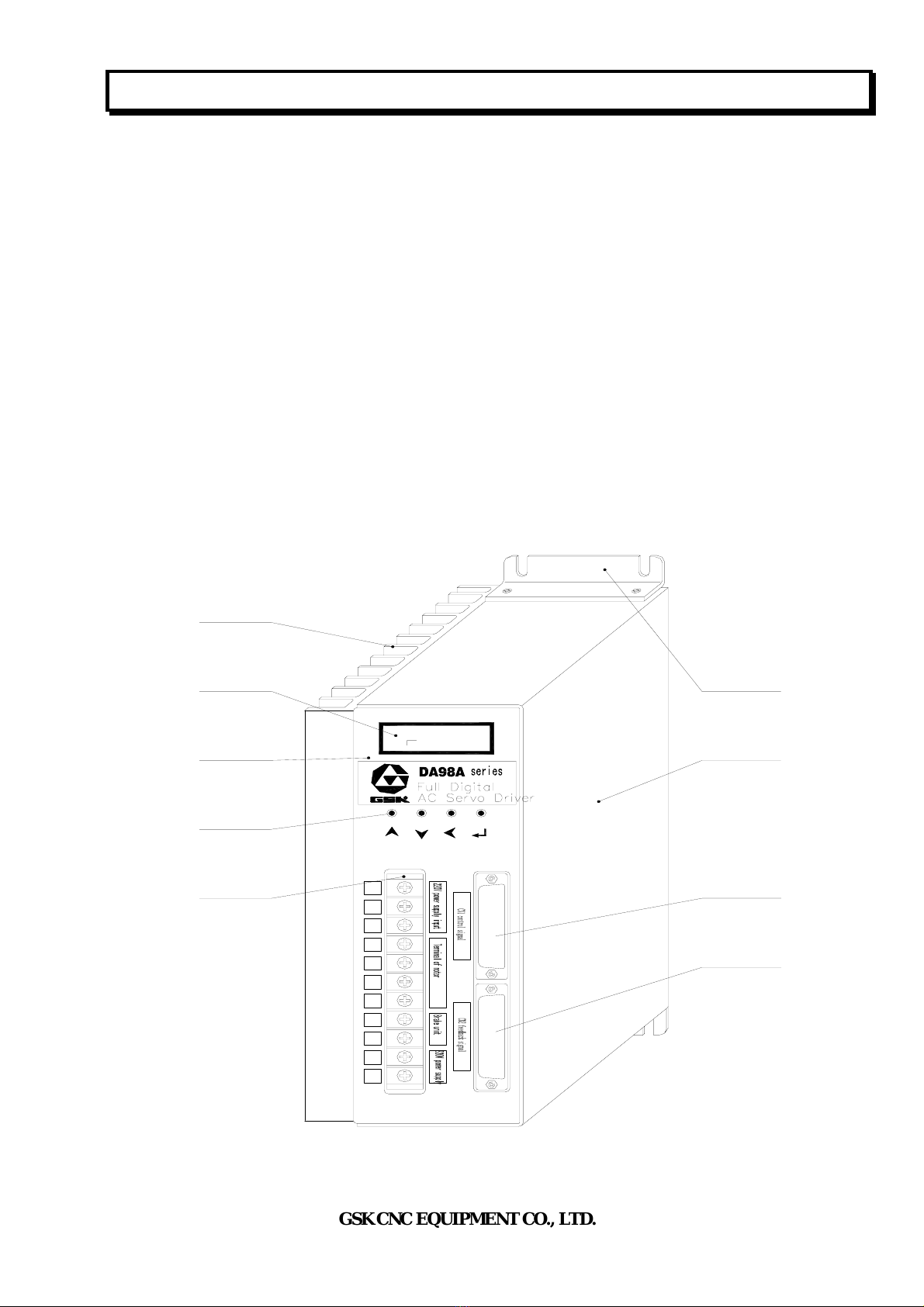
1.3 Outline..........................................................................................................................................3
Installation.......................................................................................................................................5
2.1 Environmental condition........................................................................................................5
2.2 Installation of servo driver.....................................................................................................5
2.3 Installing servomotor...............................................................................................................7
Wiring...................................................................................................................................................9
3.1 Standard wiring.........................................................................................................................9
3.2 Terminal function....................................................................................................................11
3.3 I/O Interface method.............................................................................................................14
Parameter.......................................................................................................................................17
4.1 Parameter list...........................................................................................................................17
4.2 Parameter function.................................................................................................................18
4.3 Type code parameter and motor........................................................................................22
Alarm and troubleshooting..............................................................................................24
5.1 Alarm list...................................................................................................................................24
5.2 Alarm troubleshootings.........................................................................................................25
Display and operation..........................................................................................................30
6.1 Keyboard operation...............................................................................................................30
6.2. Monitoring mode...................................................................................................................30
6.3 Parameter setting....................................................................................................................33
6.4 Parameter management........................................................................................................34
6.5 Speed trial run.........................................................................................................................36

DA98 DA98A User Manual
VI
6.6 JOG run.....................................................................................................................................36
6.7 Motor testing............................................................................................................................36
6.8 Miscellaneous...........................................................................................................................36
Run.......................................................................................................................................................37
7.1 Power supply connection......................................................................................................37
7.2 Trial run.....................................................................................................................................39
7.3 Adjustment................................................................................................................................40
Specification................................................................................................................................43
8.1 Driver specification ................................................................................................................43
8.2 Servomotor specification......................................................................................................44
8.3 Isolation transformer.............................................................................................................50
Order...................................................................................................................................................56
9.1 Capacity selections .................................................................................................................56
9.2 Electronic gear ratio...............................................................................................................56
9.3 Stop characteristics ................................................................................................................56
9.4 Servo and position controller computation method.....................................................57

DA98A User Manual
GSK CNC EQUIPMENT CO., LTD.
1
Overview
1.1 Introduction
AC servo technology has been advanced and improved since the early of 90th last century and
applied to NC machine, printing packing machinery, textile machinery, automatic production line
and other automatic fields.
With high integration, compact, excellent reliability, DA98A AC servo system is the first full digital
one in China, employed with the advanced digital signal processor DSP(TMS320f2407A) from
America TI company, large-scale complex programmable logic device and MITSUBISHI intellegent
power module, and with PID operation to execute PWM control. Its performance has reached the
same overseas level.
DA98A AC servo system has advantages
compared to stepper system as follows:
zAvoiding out-of-step
Servomotor is employed with encode, its
position signal feedbacks to servo driver with
open loop position controller to compose a
semi closed loop control system.
zSpeed ratio, constant torque
The timing ratio is 1:5000,with stable torque
from low speed to high speed.
zHigh speed, high precision
Max. speed can be 3000rpm, position
precision of turning is 1/10000r.
Note: There is different max. speed for different
types.
zSimple and flexible control
Parameters can be modified to set properly operating mode, running performance of servo system
to meet different requirements.
Positioning instruction
Controlle
r
Open loop control Stepper motor
Feedback control Servomotor
Controller
Positionin
g
instruction
Feedback

DA98A User Manual
GSK CNC EQUIPMENT CO., LTD.
2
1.2 Check after delivery
1)Check after delivery:
(1) Whether packing box is good and goods is damaged.
(2) Whether the servo driver, servo driver nameplate is the ordered ones.
(3) Whether accessories are the requirements.
zDo not install servo system which is damaged or lacks of components
zServo driver must be matched with servomotor which performance matches
the former.
zPlease contact with us or suppliers if there are any questions after receiving
goods.
2)Type signification:
(1) Type for servo driver
DA98A-04-130SJT-M060D
Adaptive to servomotor type(GSK SJT series motor) ※1
Outputpower:2-bit digit(04,06…23) corresponding to 0.4~2.3KW ※2
Series code
※ 1:It can be matched with other homemade or imported servomotor which is needed to order. The
driver which is short of parameters can be only adaptive to SJT, STZ, Star series servomotor.
※2:Small power (less than 1.5KW) is the standard configuration, and middle power (<1.5≤26KW is
employed with thicker radiator.
Note: Product type has been filled in before delivery and check the product with its nameplate.
(2) Servomotor type.
DA98A (2.0 Version) AC servo driver can be matched with many domestic and abroad
types of servomotor which can be selected by user. Servomotor information of GSK SJT
Note

DA98A User Manual
GSK CNC EQUIPMENT CO., LTD.
3
series and STZ, Star series from Huazhong University of Science and Technology are
provided in Chapter 8, and other servomotor information are provided with delivery.
3)Accessories
(1) DA98A servo driver standard accessories:
①User Manual 1
②Installation bracket 2
③M4×8 contersink bolt 4
④CN1 plug(DB25 female)1 set (note 1)
⑤CN2 plug(DB25 male)1 set (note 2)
Note 1: Signal cable (standard 3m) can be provided when it is matched with our position controller.
Note 2: User can select feedback cable (standard 3m) when our servomotor is provided.
(2) Standard accessories of servomotor are provided according to servomotor user manual
1.3 Outline
1)Outline of servo driver
R
S
T
PE
U
V
W
P
D
r
t
-3000
Feedback terminal
Signal terminal
Radiator
6-bit LED
Panel
4 — button
Power terminal TB
Cabinet
2-bracket
CN2
CN1
Fig. 1-1 Outline of driver

DA98A User Manual
GSK CNC EQUIPMENT CO., LTD.
4
2)Outline of servomotor
Fig. 1-2 Outline of SJT series servomotor

DA98A User Manual
GSK CNC EQUIPMENT CO., LTD.
5
Installation
zStorage and installation must be a proper environmental condition.
zDo not put many packing boxes in piles to protect from being damaged and fallen
zProducts are employed with original packing boxes in delivery.
zProducts which are damaged or lacks some components must not be installed.
zProducts are installed with fireproofing and must not be installed on or near flammable to
avoid fire accident.
zServo driver must be installed in electricity box to prevent dust, corrosive air, liquid,
conductors and inflammable substances from entering it.
zProtect the servo driver and servomotor from being vibrated and shocked.
zProtect motor wire, motor spindle and encoder from be dragged.
2.1 Environmental condition
Item DA98A servo driver GSK SJT series servomotor
Operating
temperature
0~55℃(no freezing)
below 90%RH(no dewing)
-25~40℃(Star)no freezing, below 90%RH(no
dewing)
Storage/delivery
temperature/humidity
-20~80℃
90%RH(no dewing)
-25~70℃
below 80%RH(no dewing)
Atmosphere
environment
No corrosive gas,flammable gas,
oil fog or dust in control cabinet
No corrosive gas,flammable gas, oil fog or dust in
storehouse(no insolation)
Altitude Altitude: below 1000m Altitude: below 2500m
Vibration Less than 0.5G(4.9m/s2)10-60HZ(non-continuous run)
Guard level IP00(no guard)IP65
2.2 Installation of servo driver
zIt must be installed in a protective electric cabinet.
zIt must be installed in the specified direction and interval to get good heat sink.
zIt must not be installed on or near flammable objects to avoid fire.
1)Installation environment
(1) Guard
The servo driver without guard must be installed in the protective electric cabinet to prevent
dust, corrosive gas, liquid, electricity-conduct or inflammable substances from entering it.
Note
Note

DA98A User Manual
GSK CNC EQUIPMENT CO., LTD.
6
(2) Temperature and humidity
Environmental temperature is 0-50℃, and long-term safe operating temperature is below 45℃
to get good heat sinking.
(3) Vibration and impact
The servo driver must be protected from vibration which is below 0.5(4.9m/S2) and driver
cannot receive weight and impact.
2)Installation method
(1) Installation mode
The driver is employed with bottom board or panel installation mode in the upright direction of
installation side.
Fig 21. is sketch map for bottom board installation and Fig.2.2 is one for panel installation.
(2) Installation interval
Fig. 2.3 is installation interval for one driver and Fig. 2.4 is for drivers. The interval for actual
installation should be more as possible to get good heat radiation.
Fig. 2.3 Installation interval for one driver
Fig. 2.1 bottom board installation mode
Fig. 2.2 driver panel installation mode
Data in( )is applied to driver with medium power

DA98A User Manual
GSK CNC EQUIPMENT CO., LTD.
7
Servo driver
Servo driver
Servo driver
>100mm
>100mm
>100mm>25mm >25mm
Ventilation direction Ventilation direction
Fig. 2.4 Installation interval for drivers
(3) Heat radiation
There should be convective wind blown to the radiator in electric cabinet to protect its
environmental temperature from continuous rising.
2.3 Installing servomotor
zProtect motor shaft or encoder from pounding to avoid vibration or
impact.
zDo not drag the motor shaft, outgoing line or encoder.
zMotor shaft cannot be over loaded, otherwise which may damage
motor.
zMotor must be installed firmly and there should be measures against
loose.
1)Installation environment
(1) Guard
GSK SJT series, Star series servomotors from Huazhong University of Science and
Technology are not employed with waterproof device. So, protect liquid from splashing on
motor and grease from motor internal by its lead wire and shaft.
Note: Please remark in order if you need servomotor with waterproof.
(2) Temperature and humidity
Environmental temperature should be -25~40℃(no freezing). Measures of heat radiation
must be done when the motor’s temperature rises owing to long-term run, if there is small
surrounding space or there is heating equipment nearby.
Note

DA98A User Manual
GSK CNC EQUIPMENT CO., LTD.
8
(3) Vibration
Servomotor should not be installed in vibrational environment and its vibration should be
less than 0.5G(4.9m/s2).
2)Installtion method
(1) Installtion mode
SJT, Star series motors are employed with flange installation mode in every direction.
(2) Cautions:
zDo not hammer motor or its shaft to protect it from damaging encoder when removing belt
wheel. Helical instruments are employed to removing it.
zSJT, Star series motor cannot be weighted with heavy axial, radial load. It should be
employed with flexible shaft coupling to load.
zAnti-loose washer is employed to fix motor to protect it from loose.

DA98A User Manual
GSK CNC EQUIPMENT CO., LTD.
9
Wiring
●Only qualified persons can connect the system or check the connection
●Wiring and check cannot be done in 5 minutes after the power supply is switched off to
avoid electric shock.
●Connect with voltage and polarity of terminal to avoid damaging equipment and
injuring pepole.
●Driver and servomotor must be grounded.
3.1 Standard wiring
External connection of driver is relative to control mode.
1)Position control mode:
Fig. 3.1 is standard wiring of position control mode.
2)Wiring
(1) Power supply terminal TB
zWire size:wire size of R, S, T, PE, U, V, W ≥1.5mm2(AWG14-16),wire size of r, t≥1.0
mm2(AWG16-18).
zGrounding: the grounding wire should be thick, PE terminals of driver and servomotor
should be eathed and their resistance is less than 100Ω.
zThe terminal is employed wth SVM2-4 pre-insulation coldpress to be connected firmly.
zIt should suggest that it is employed with three-pahse isolation transformer to power on
to avoid electric shock to person.
zIt should be suggested that power supply is connected by noise filter to improve
anti-interference ability.
zInstall non-fusing breaker to cut off external power supply timely when the driver is fault.
(2) Control signal CN1, feedback signal CN2
zWire diameter: it is employed with shield cable, wire diameter ≥0.12mm2(AWG24-26)
and shield layer must be connected with FG terminal.
zLength: the cable length should be as possible as short, one to control CN1 should be less
than 3m, and another to control feedback signal CN2 should be less than 20m.
zWiring: be far away from power circuit to wiring to antiinterference.
zInductive components (coil) should be installed with surge absorbing element: DC coil
parallels reversely with freewheeling diode and AC coil parallels with RC absorption circuit.
Warning
Caution

DA98A User Manual
GSK CNC EQUIPMENT CO., LTD.
10
zU, V, W should be connected with motor winding one by one.
zCable and lead wire must be fixed to avoid to approach radiator of driver and motor,
which will ensure the insulation.
zDo not touch driver and motor in 5 minutes after the power supply is switched off
because there is large electrolytic capacitance to keep high pressure even if they are
switched off.
Fig. 3.1 Standard wiring of position control mode
Note
17
PE
Position instruction
Encoder in Z direction
outputs public terminals
Encoder in Z direction outputs
Output public terminal
Servo alarm
Servo ready OK
Servo enabling
or sin
g
le
p
hase
Three-phase Servo drive
r
Servomotor
Moto
r
Encoder

DA98A User Manual
GSK CNC EQUIPMENT CO., LTD.
11
3.2 Terminal function
1)Terminal configuration
Fig. 3.2 is for interface terminal configuration of servo driver. TB is terminal block; CN1 is
DB25 connector assembly,socket is male and plug is female; CN2 is DB25 connector
assembly, socket is female and plug is male.
1
14
2
15
3
16
4
17
5
18
6
19
7
20
8
21
9
22
10
23
11
24
12
25
13
CN1
DB25
1
14
2
15
3
16
4
17
5
18
6
19
7
20
8
21
9
22
10
23
11
24
12
25
13
CN2
DB25
COM+
ALM
COIN/SCMP
CZ
SRDY
DG
DG
DG
DG
CZCOM
PULS+
PULS-
SIGN+
SIGN-
COM+
SON
ALRS
FSTP
RSTP
CLE/SC1
INH/SC2
FG
FIL
FG
RIL
MHP
NC
A-
A+
B-
B+
Z-
Z+
U-
U+
V-
V+
W-
W+
+5V
+5V
+5V
+5V
0V
0V
0V
FG
0V
FG
0V
R
S
T
E
U
V
W
P
D
r
t
TB
Fig. 3.2 Interface terminal configuration of servo driver`
2)Power supply terminal TB Table3.1 power supply terminal
Terminal No. Terminal sign Signal name Function
TB-1 R
TB-2 S
TB-3 T
Main loop power supply:
single phase or
three-pahse
Power supply input terminal of main loop
~220V 50Hz
Note: do not connect with motor output terminal U, V, W.
TB-4 PE System be grounded Ground terminal
Ground resistance<100Ω
Common terminal of servomotor input and power
Supply input must be grounded
TB-5 U
TB-6 V
TB-7 W
Servomotor output Output terminal of servomotor must be
connected correspondingly with U, V, W
TB-8 P standby
TB-9 D standby
TB-10 r Control power supply: Power supply input terminal of control loop
PE

DA98A User Manual
GSK CNC EQUIPMENT CO., LTD.
12
TB-11 t single phase ~220V 50Hz
3)Control terminal CN1
Table 3.2 Input/output terminal CN1 of control signal
T
erminal No. Signal name Sign I/O Mode Function
CN1-8
CN1-20
Power supply
positive of input
terminal COM+ Typel
Power supply positive of input terminal
Photoelectric coupling used for driving input
terminal
DC12~24V,Current≥100mA
CN1-21 Servo enabling SON Typel
Input terminal of servo enabling
SON ON:enabling driver operating
SON OFF:close driver not to operate, and motor is
in free state.
Note 1: The motor must be stationary before it is
switched from SON OFF to SON ON;
Note 2: Waits for 50ms before inputting command
after it is SON ON.
CN1-9 Alarm clearance ALRS Typel NC
CN1-1 Servo ready
output SRDY Type2
Servo ready output terminal
SRDY ON:the control power supply and the main
power supply are normal, the driver does not alarm
and the Servo Ready OK outputs ON.
SRDY OFF:the main power supply is switched off
or the driver alarms and the Servo Ready OK
outputs OFF.
CN1-15 Servo alarm
output ALM Type2
Servo alarm output terminal
ALM ON:the servo driver does not alarm and the
servo alarm outputs ON.
ALM OFF:the servo driver alarms and the servo
alarm outputs OFF.
CN1-3
CN1-4
CN1-16
CN1-17
Common of
output terminal DG Control the public terminal of ground wire of signal
output terminal(except for CZ)
CN1-2 Encoder(Z
phase ) output CZ Type2
Output terminal of encoder(Z)
Photoelectric encoder pulse(Z) of servomotor
output
CZ ON:signal (Z) appears
CN1-5
Public terminal
of encoder (Z
phase)
CZCOM Public terminal of encoder (Z) output terminal
CN1-18 PULS+
CN1-6
Instruction pulse
PLUS input PULS- Type3 P
CN1-19 SIGN+
CN1-7
Instruction pulse
SIGN input SIGN- Type3 P
External instruction pulse input terminal
CN1-24 Shield ground FG Terminal of shield ground wire

DA98A User Manual
GSK CNC EQUIPMENT CO., LTD.
13
CN1-25 wire
4)Feedback signal terminal CN2
Table 3.3 Signal input/output terminal CN2 of encoder
Terminal signTerminal
No. Signal name Sign I/O Mode
Color Function
CN2-5
CN2-6
CN2-17
CN2-18
Power supply output( +) +5V
CN2-1
CN2-2
CN2-3
CN2-4
CN2-16
Power supply output(-) OV
The servomotor photoelectric encoder
connects with +5V power supply;
multi-core wire in parallel are used
when the length of cable is too long.
CN2-24 Encoder(A+) input A+ Connect with servomotor photoelectric
encoder(A+)
CN2-12 Encoder(A-) input A-
Type4 Connect with servomotor photoelectric
encoder(A-)
CN2-23 Encoder(B+)input B+ Connect with servomotor photoelectric
encoder(B+)
CN2-11 Encoder(B-) input B-
Type4 Connect with servomotor photoelectric
encoder(B-)
CN2-22 Encoder(Z+)input Z+ Connect with servomotor photoelectric
encoder(Z+)
CN2-10 Encoder (Z-)input Z-
Type4 Connect with servomotor photoelectric
encoder(Z-)
CN2-21 Encoder(U+)input U+ Connect with servomotor photoelectric
encoder(U+)
CN2-9 Encoder(U-) input U-
Type4 Connect with servomotor photoelectric
encoder(U-)
CN2-20 Encoder(V+)input V+ Connect with servomotor photoelectric
encoder(V+)
CN2-8 Encoder (V-) input V- Type4 Connect with servomotor photoelectric
encoder(V-)
Other manuals for DA98A
1
Table of contents
Other GSK Servo Drive manuals