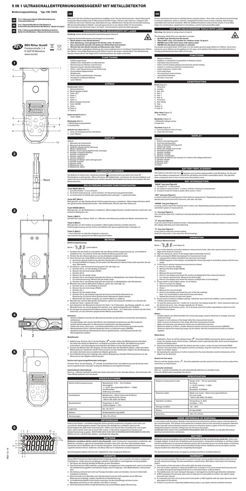
GSSI UtilityScan DF User manual

UtilityScan®DF
Quick Start Guide
MN72-489 Rev G

Copyright© 2017-2018 Geophysical Survey Systems, Inc.
All rights reserved
including the right of reproduction
in whole or in part in any form
Published by Geophysical Survey Systems, Inc.
40 Simon Street
Nashua, NH 03060-3075 USA
Printed in the United States
SIR, RADAN, UtilityScan and PaveScan are registered trademarks of Geophysical Survey Systems, Inc.

UtilityScan®DF Quick Start Guide
A Fast Check List for Field Operation
UtilityScan® DF ........................................................................................................................................................ 1
Section 1: Getting Started.................................................................................................................................... 2
Keyboard and Snipping Capability ..................................................................................................................2
Toughpad Information .........................................................................................................................................3
Standard Icons .........................................................................................................................................................4
Display Channel (Frequency) Icons..................................................................................................................4
Powering and Booting Up...................................................................................................................................5
Powering Down.......................................................................................................................................................7
Section 2: 2D Data Collection and Playback.................................................................................................. 8
New Project Mode and Last Project Mode....................................................................................................8
Configuring the Main Menu Options (Right Pane of the Screen) ..................................................... 12
Collecting 2D Data............................................................................................................................................... 24
2D Data Playback Mode .................................................................................................................................... 28
Section 3: 3D Data Collection and Playback................................................................................................32
Playback 3D Data ................................................................................................................................................. 41
Appendix A: Dielectrics of Common Materials (Soil Conditions) .........................................................48
Appendix B: Examples of Some Common Objects ...................................................................................49
Appendix C: Glossary of Terms ........................................................................................................................54
Appendix D: Connect and Configure GPS....................................................................................................58

Limited Warranty, Limitations Of Liability And Restrictions
Geophysical Survey Systems, Inc. hereinafter referred to as GSSI, warrants that for a period of 24 months from the
delivery date to the original purchaser this product will be free from defects in materials and workmanship. EXCEPT
FOR THE FOREGOING LIMITED WARRANTY, GSSI DISCLAIMS ALL WARRANTIES, EXPRESS OR IMPLIED,
INCLUDING ANY WARRANTY OF MERCHANTABILITY OR FITNESS FOR A PARTICULAR PURPOSE. GSSI's
obligation is limited to repairing or replacing parts or equipment which are returned to GSSI, transportation and insurance
pre-paid, without alteration or further damage, and which in GSSI's judgment, were defective or became defective during
normal use.
GSSI ASSUMES NO LIABILITY FOR ANY DIRECT, INDIRECT, SPECIAL, INCIDENTAL OR CONSEQUENTIAL
DAMAGES OR INJURIES CAUSED BY PROPER OR IMPROPER OPERATION OF ITS EQUIPMENT, WHETHER
OR NOT DEFECTIVE.
Before returning any equipment to GSSI, a Return Material Authorization (RMA) number must be obtained. Please call
the GSSI Customer Service Manager who will assign an RMA number. Be sure to have the serial number of the unit
available
Regulatory Information
Please see the GSSI Manual CD or our website, www.geophysical.com/regulatoryinformation.htm, for current
information and FCC Registration Form, including:
•FCC Notice for U.S. Customer
•Canadian Requirements for RSS-220
•Declaration of CE Conformance


UtilityScan DF Quick Start Guide Page 1
UtilityScan®DF
2
1
3
4
5
1
Control Unit (Panasonic Toughpad FZ-G1)
2Ethernet Cable
3Dual Frequency Antenna with battery
42 Wheel Cart with front antenna mount,
Or
54 Wheel Cart with capsule and foam insert
for antenna

UtilityScan DF Quick Start Guide Page 2
Section 1: Getting Started
Thank you for purchasing a UtilityScan DF from GSSI! The UtilityScan DF incorporates our innovative dual-frequency
digital antenna (300 and 800 MHz) and an easy-to-use touchscreen interface to view shallow and deep targets
simultaneously in a single scan. You can also take advantage of GSSI’s world-renowned versatility and use our excellent
350 MHz HyperStacking antenna with the same control tablet and cart.
GSSI application support and training services are also at your disposal. Simply call (603) 893-1109 or email
training@geophysical.com with questions. We’d love to hear from you!
Keyboard and Snipping Capability
The Panasonic FZ-G1 Toughpad®is designed to be used as a touch screen. You may use your fingers to tap on an icon
or menu option, or you may use the attached stylus pen.
Snipping Tool: Press the A2 button once to open the Windows®Snipping Tool.
Keyboard:There is keyboard capability on the
Toughpad. To access the keyboard press and hold the
A2 button until the keyboard appears. You may exit
the keyboard by tapping on the “X” located on the
upper right-hand corner of the keyboard.

UtilityScan DF Quick Start Guide Page 3
Toughpad Information
Power Indicator
•Green: Power is on.
•Blinking Green:Sleep Mode.
•Blinking Green and Orange: Cannot power on or resume due to low temperature.
Battery Indicator: A fully charged battery should last between 10-12 hours. Charging the battery takes
approximately 4 hours.
•Not lit:Battery is not being charged.
•Orange:Charging.
•Green:Fully charged.
•Red:Remaining power is 9% or less.
•Blinking Orange:Battery can temporarily not be charged because the internal temperature is too high.
Note: If the Toughpad battery dies and the system shuts down during data collection
you will need to recharge the battery. All of the data collected to the point of the
system shutting down was saved and can be retrieved from the project folder.

UtilityScan DF Quick Start Guide Page 4
Standard Icons
There are icons that will perform the same function throughout the system. They are as follows:
•Change values up or down, or highlight menu options or files.
•Accept the value.
•Test the value.
•Cancel.
The icons will display as red or white, depending upon whether or not it was the most recent selected option.
An icon will appear blue if it is hovered over with the stylus pen.
Display Channel (Frequency) Icons
These icons will indicate what type of display is on the screen. Also, by tapping on them, the display will change
according to which one is selected.
•High Frequency (800 mhz)
•Low Frequency (300 mhz)
•Blend
•All Three

UtilityScan DF Quick Start Guide Page 5
Powering and Booting Up
1Assemble the cart as shown in the Resource
Guide: Cart Assembly Instructions. Currently
available on the GSSI Tech Support website:
https://support.geophysical.com.
Important: Antenna battery must be attached
to the antenna before continuing to Step 2.
2To power up the system:
a) Press and hold the power button on the
Toughpad for about 2 seconds until a
green light illuminates beside the power
button. The COMM light will illuminate
green and the PWR light will illuminate
red. The PWR light will turn blue once the
antenna has finished starting up.
b) After a few seconds, when the system boot up is complete, the UtilityScan DF Start Screen is displayed.
3Press the A1 button to start.

UtilityScan DF Quick Start Guide Page 6
4Select how the data will be displayed and collected.
Press the Units icon to toggle between Metric or
English units.
5Select between 2D or 3D Data Collection Mode
by pressing the Mode button.
6Select whether to collect or playback data:
•Playback Only: To playback data previously
collected and saved.
•New Project: To configure and collect data
for a new project.
•Last Project: Collect data using the same
configuration as the last project.
7If there is no communication between the Toughpad and the antenna, or there is no antenna attached to the Toughpad,
“New Project” and “Last Project” will display as “No Antenna Found” and a red “X” will appear over the antenna
icon. The green light on the antenna in the capsule will illuminate if communication is established.
No Communication Established with Antenna
Communication Established with Antenna

UtilityScan DF Quick Start Guide Page 7
Powering Down
It is essential that these steps are followed in order when powering down the system.
Failure to do so may result in boot-up issues*.
1From the Setup Screen tap on System Options.
2Tap on System Shutdown.
3Tap either:
Exit:Close Application to return to start
screen. At this point, press and hold the power
button for about 3 seconds.
The system will shut down properly.
Power Off:Close Application and turn OFF
System power. The system will automatically
shut down. (Recommended)
Note: If the system was not powered down properly and before the next time you
power up, you must disconnect the battery on the antenna and then re-connect it.
This will turn the antenna off, then back on. You can now power up normally.

UtilityScan DF Quick Start Guide Page 8
Section 2: 2D Data Collection and Playback
New Project Mode and Last Project Mode
New Project Mode:Configure the system as desired. This opens the Change Data Path screen and allows for the
selection or creation of a project folder.
After selecting New Project, select which folder you would like to save your
data to, or create a new folder for a new project.
1Tap on the arrows and select a folder (project). All files will be saved to
this folder and the name of the files will be folder name + a sequential
number. Tap on Accept to continue.
2Tap on New Data Path to create a new folder (project).
•Enter and save the new folder (project) name.
•Highlight the new folder (project) by tapping on the arrows.
•Tap on Accept to continue.
3Tap on Cancel. The files will be saved to the last folder that was used.
Last Project Mode:Bypass the Change Data Path screen and continue with the last project and all of its settings.

UtilityScan DF Quick Start Guide Page 9
In either mode, the Setup options are the same. The following screen is displayed once a folder is created or
Last Project Mode is selected:
The Screen is divided into three sections: Data View (Linescan and O-Scope), Main Menu located at the right pane
of the screen, and the Sub-Menu located at the bottom of the screen.

UtilityScan DF Quick Start Guide Page 10
Status screen located at the lower left corner of the screen.
•GPS Status
•Disk Space Used (storage space)
•Battery Power remaining for the antenna
•Battery Power remaining for the Toughpad
The Data View screen will display data in any one of the follow views:
•High Frequency
•Low Frequency
•Blend
•All Three (Default)
Switching between Data View screens and frequencies.
•Display just one frequency at a time by tapping the icon at the top of the O-Scope.
•Tapping the frequency icon again will display all three modes.

UtilityScan DF Quick Start Guide Page 11
High, Low, Blend, and Active Frequency Symbols
High Frequency
Low Frequency
Blend
Active Display

UtilityScan DF Quick Start Guide Page 12
Configuring the Main Menu Options (Right Pane of the Screen)
Signal Process Menu
Scan
•Depth Range: Choose an investigation depth. Preset depth options are available and paired for each
antenna frequency.
•Dielectric Constant: Enter the Dielectric of the soil if known (See Appendix C for more Dielectric
information).
•Soil Type: Choose a basic soil type from a menu of preset types. Each of these has an associated dielectric value.
•Scan Density: Possible choices are: Normal (18/ft or 50/m) and High (36/ft or 100/m).
•Autosave: The system will automatically save each file if this is turned on. When off, the system will prompt you to
save/discard.

UtilityScan DF Quick Start Guide Page 13
Gain Settings
•Gain Mode
•Auto: Allows the system to adjust the Gain Curve (red line seen in the
O-Scope view) automatically based on the quality of the GPR signal.
•Manual: Allows you to adjust the Gain Curve.
•Number of Points
•Number of Gain Points or “Individual Sections” to adjust the Gain Curve.
•Ranges for 1 point to 8 points.
•GP 1-8 (dB)
•If Manual Gain Mode is selection, adjust each Gain Point accordingly.
•Values range from -42 to 126.
Note: Tap on the
double arrows (up
or down) to
display the
appropriate gain
points.

UtilityScan DF Quick Start Guide Page 14
Filters (See Appendix C for more information)
•Stacking (scans): To reduce random or high frequency noise (static or fuzz) in your data. This value should be set
low (3-5). The system will average together that number of scans and output the average value.
•Background Removal (scans): Remove horizontal banding in your data. This value should be set very high. The
system will remove flat bands in the data of that many scans or higher.
•Signal Floor: Shows a visual indicator of noise levels. The shaded green area indicates an area of degraded signal in
which some target types (weak reflectors) may not be readily visible.
•Migration: Allows the computer to estimate a dielectric constant by examining the shape of the hyperbolas.
•Hilbert Transformation: Change all migrated targets from having a negative and positive polarity to just positive
polarity. Good for giving an idea of the strength of the reflection.
Horizontal Banding Example
Signal Floor Example
Other manuals for UtilityScan DF
1
Table of contents
Popular Metal Detector manuals by other brands

Bounty Hunter
Bounty Hunter pioneer 101 owner's manual

Vallon
Vallon VMH3CS Operation manual

Accurate Locators
Accurate Locators XL16 IMAGER user guide

White’s Electronics
White’s Electronics 6000/DI PRO SL instruction manual

Sibel
Sibel MOLE operating manual

Harbor Freight Tools
Harbor Freight Tools 67378 Set up and operating instructions