9
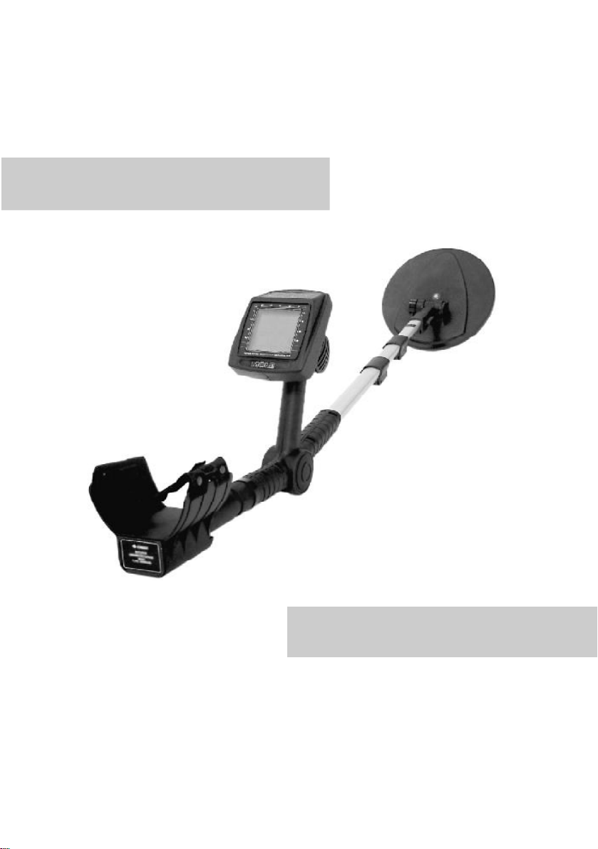
PORTABLESELECTIVEMICROPROCESSORMETALDETECTORMOLE
Specialoperatingmode
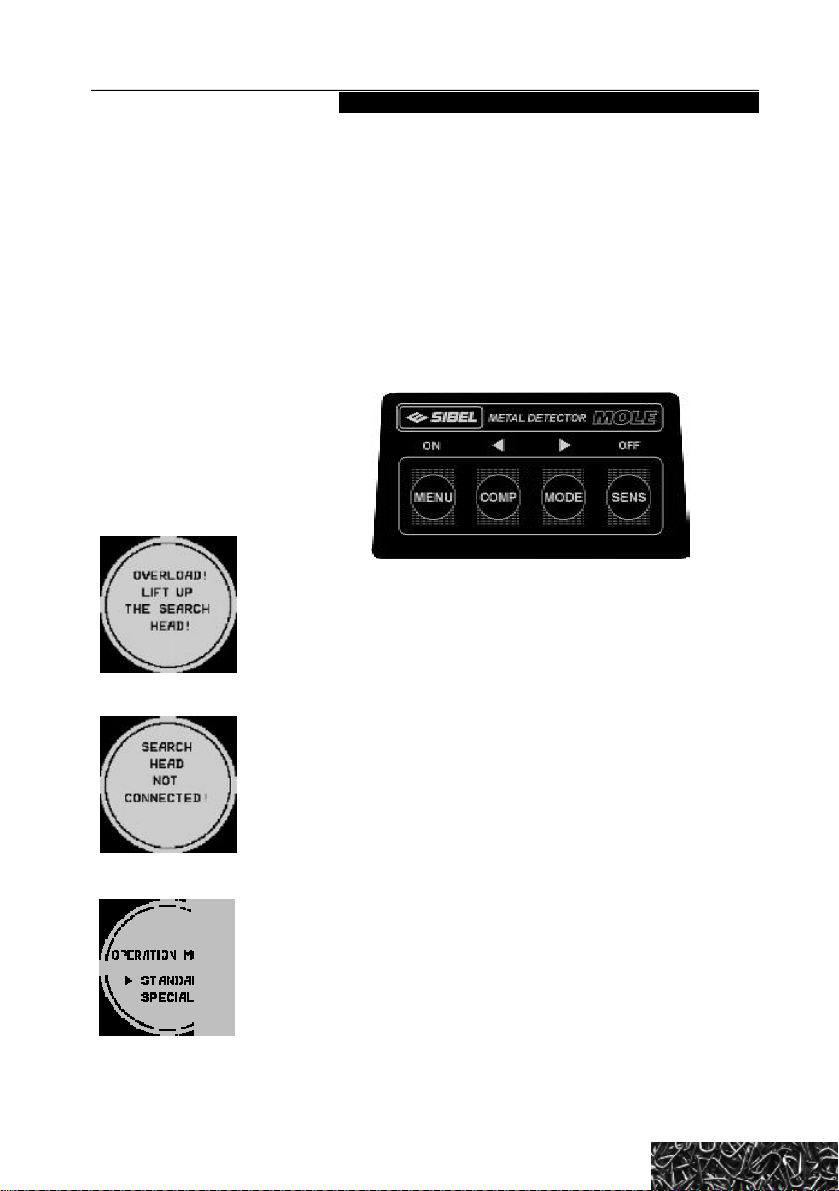
In thespecialoperatingmode(fig.12)afterswitching offthe
deviceall changedparametersarekept.
Atpressingthe «MENU» button, «Maskoff» (fig.13)
pictogram appearsat LCD.Maskingmodeisswitchedon
(fig.14)by pressing «>»button,and switchedoffby
pressing«<»button.Shifttoselectingleftboundmask(fig.15)
isperformedbypressingthe «MENU» buttoninthemasking
mode. Withthehelpof «<»and«>»buttonsusermaysetthe
requiredmaskingbound (fig.16).
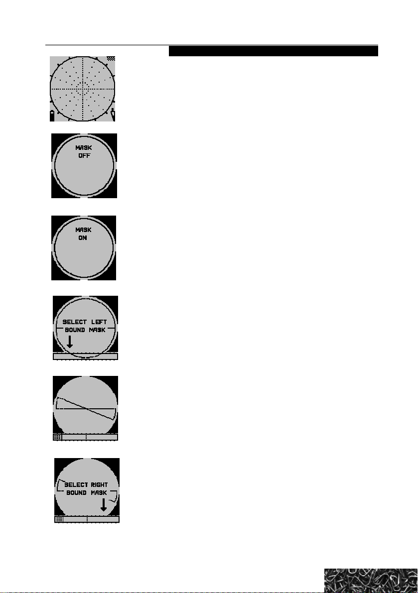
Maskingisunderstoodasshadingof apartof bottomrect-
angle,at the lefthalfof which,at thetime of objects detection,
ferrousmetalsareindicatedasahairline, attherighthalf-non-
ferrousmetals. Inthemaskingmodeaudioalarmis switchedoff
incasethesignalfromtheobjectisintheselectedmask(sector)
orthehairline,correspondingtothetypeof detectedobject
appearswithintheshadedarea.
Nextpressingthe «MENU» buttoncauses «Selectright
bound mask»pictogramatLCD(fig.17).Withthehelpof «<»
and«>»buttonsusermaysettherequiredmaskingbound(fig.
18).Incasetherightboundoverlaystheleftone,awindow
betweenthemwillbemasked(fig.19,20).Thus,thereisanoption:
audioalarmmayaccompanyeitherthedetectionofdefinitetype
of object, orthedetectionof all objects, except unnecessary.
Afternextpressing the«MENU»buttonaudioalarmloudness
volumepictogram appearsatLCD(fig.7).Withthehelpof«<»
and«>»buttonsusermaysettherequiredaudioalarmloudness.
Afternextpressing the “MENU” button“Sensitivityto
grounddiscontinuity”pictogram will appearat LCD (fig.21).
Withthehelpof «<»and«>»buttonsusermaysetonefrom
OPERATING MANUAL
fig.12
fig.13
fig.14
detect grounddiscontinuities, thedevice shouldbeswitchedto
appropriatemode(fig.11)withthehelpofthe «MODE»button.
Attherightbottomcornerthereisatriangle.After
switchingonit ishalf-filledthat correspondstotheaverage
sensitivity.Afterpressingthe «SENS» button,sensitivitywillbe
minimal(thetrianglewillbeminimum-filled).Atnextpressingthe
sensitivitywillbe maximal (thetrianglewillbefilledcompletely).
Afternext pressingthe buttonthe sensitivitycomesbacktoits
averagelevel(thetriangleishalf-filled).Furtherprocess of the
sensitivitychangingis the same.
fig.15
fig.16
fig.17