Vallon VMH3CS User manual

Vallon GmbH • Arbachtalstr. 10 •72800 Eningen • Germany
Phone: +49-7121-98550 • Fax: +49-7121-9855-100 •
Searching with Excellence
METAL DETECTOR
VMH3CS
Software Version 1.14_click
OPERATION MANUAL
Issue 07/2007

1
Metal Detector VMH3CS – Operation Manual
© 2007 Vallon GmbH, D-72800 Eningen/Germany
Notes concerning the Electromagnetic Compatibility (CE)
This detector corresponds to class B according to EC-guideline 89/336/EWG.
If the detector is used in accordance with the regulations, changes of the
electromagnetic surroundings are measured and indicated.
Therefore, the detector cannot suppress all noise frequencies. In worst case other
electronic instruments may release false alarms due to their radiated emissions.
A further functional disorder – not recognizable by the operator – does not occur.

2
Metal Detector VMH3CS – Operation Manual
© 2007 Vallon GmbH, D-72800 Eningen/Germany

3
Metal Detector VMH3CS – Operation Manual
© 2007 Vallon GmbH, D-72800 Eningen/Germany
CONTENTS
1. GENERAL APPLICATION.................................................................................. 5
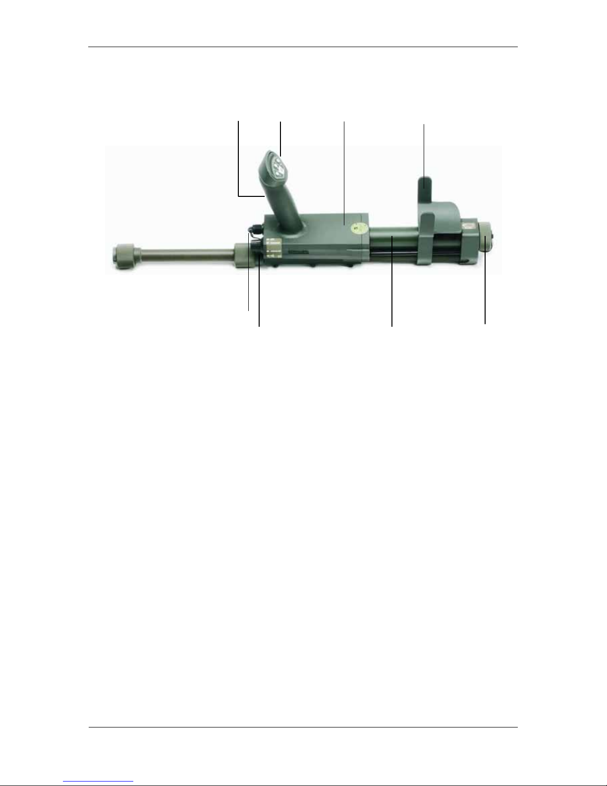
2. DESIGN FEATURES .......................................................................................... 7
2.1 Detector Electronics................................................................................................................. 9
2.2 Search Head with Telescopic Pole....................................................................................... 11
2.3 Headset with textile ribbon (optional accessory) ............................................................... 12
3. OPERATION..................................................................................................... 13
3.1 Individual Alarm Configurations........................................................................................... 15
3.2 Switching ON and OFF and Program Settings.................................................................... 16
3.2.1 Confidence Click............................................................................................................. 16
3.3 Fine Adaptation to Mineralized Soil...................................................................................... 17
3.3.1 Automatic Fine Adaptation to Mineralized Soil............................................................... 17
3.3.2 Manual Fine Adaptation to Mineralized Soil................................................................... 18
3.3.3 Important Notes.............................................................................................................. 19
3.4 Setting the Detection Sensitivity .......................................................................................... 20
3.5 Operational Readiness, Sensitivity Test Piece ................................................................... 21
3.6 Checking the Battery Capacity Level................................................................................... 22
4. AUDIO ALARM SIGNALS DURING OPERATION........................................... 23
4.1 Full Battery Charge Signal (Simulation)............................................................................... 23
4.2 Battery Charge Signal with 50 % of Capacity (Simulation)................................................ 23
4.3 Low Battery Charge Signal (Simulation).............................................................................. 24
4.4 Detector "Non Functioning" Signal (Simulation)................................................................ 24
4.5 Typical Target Detection Signals.......................................................................................... 25
5. VISUAL SIGNALS ............................................................................................ 28
5.1 Visual Signals during Detection ........................................................................................... 28
5.2 Visual Error Messages, Cause and Remedy ....................................................................... 30
6. VIBRATION SIGNALS DURING THE DETECTION WORK............................. 31
7. PRACTICAL DETECTION WORK.................................................................... 32
7.1 Pinpointing.............................................................................................................................. 32

4
Metal Detector VMH3CS – Operation Manual
© 2007 Vallon GmbH, D-72800 Eningen/Germany
7.2 Detection in Non-Overgrown Areas with the Oval Search Head....................................... 33
7.3 Detection in Overgrown Areas with the Oval Search Head ............................................... 33
7.4 Detection in Waters................................................................................................................ 34
8. Simultaneous operation of two DETECTORS in close vicinity ................... 35
9. DATA input / DATA OUTPUT.......................................................................... 36
9.1 Computer aided UXO detection ............................................................................................ 36
9.2 Firmware Upgrade.................................................................................................................. 36
APPENDIX A – LIST OF AUDIO SIGNALS 37
APPENDIX B – SHORT INSTRUCTIONS 38
APPENDIX C – TECHNICAL DATA 40
APPENDIX D – DIMENSIONAL DRAWINGS 42
APPENDIX E – SPARE PARTS 43
APPENDIX F – UXO SEARCH HEAD (OPTIONAL ACCESSORY) 47
APPENDIX G – STICK PROBE (OPTIONAL ACCESSORY) 55

5
Metal Detector VMH3CS – Operation Manual
© 2007 Vallon GmbH, D-72800 Eningen/Germany
1. GENERAL APPLICATION
The use of the Metal Detector in accordance with the regulations is the
detection of metal parts in mines or in ammunition or explosive ordnance in
the ground and in shallow water. The search head must be moved above the
ground in such a way that obstacles like grass, stones, branches or explosive
ordnances are not touched.
ATTENTION: Danger of Explosion.
Do not use the metal detector for scanning persons.
The Metal Detector is consisting of two parts: control unit with telescopic pole
and a pluggable oval search head. As an optional accessory a large UXO
search head or a stick probe can be connected.
The oval search head is recommended for the detection of metal mines and
plastic mines with minimum metal content as well as other small metal parts.
The large UXO search head is recommended for the detection of shells,
bombs and other ammunition in larger depths.
The stick probe is recommended for detection even in hollow spaces, bushes
and trusses of hay.
The detector has been designed for the highly accurate detection of all types
of ferrous and non-ferrous metals. Ease of operation and a rigid and compact
mechanical design ensure very reliable operation for professional ordnance
clearing in battlefield operations and rigorous military training programs.
Along with its digital signal processor the metal detector uses the function
principle of an advanced pulse-field specially improved by Vallon. It can work
also in strongly mineralized soils, like laterite, magnetite, magmatite as well as
in shallow water (salt and fresh water) and under the electromagnetic
influence of main power lines without affecting the detector’s sensitivity too
much.
The metal detector ready for service, including accessories, is delivered in a
rigid carrying bag.

6
Metal Detector VMH3CS – Operation Manual
© 2007 Vallon GmbH, D-72800 Eningen/Germany
WARNING
The Metal Detector detects metals only. Each audio signal may indicate a
mine with metal content or an UXO. Mines containing only small metal parts
with very special metallic alloy may eventually not be detected. Mines without
any metal part will not be detected.
Before starting detection work make the performance test as described in
chapter 3.5.
WARNING
DO NOT USE THE METAL DETECTOR FOR LOCATING MAGNETICALLY
INFLUENCED MUNITIONS.
Some of the known mines of NATO-countries will not be activated, provided
the detector is equipped with non-magnetic batteries. For detection of mines of
other manufacturers it is recommended to test in advance whether they are
detectable before the operator starts the detection work.

7
Metal Detector VMH3CS – Operation Manual
© 2007 Vallon GmbH, D-72800 Eningen/Germany
2. DESIGN FEATURES
The Metal Detector VMH3CS, packed ready for service, consists of the
following main components:
(1) Detector electronics with integrated arm-rest, battery compartment,
ON/OFF switch for two different ground conditions, non-magnetic
loudspeaker and vibrator. Integrated two-piece telescopic carrying bar
with plug-in connection for search head
Hand grip with LED-bargraph (14 elements), 4 rigid push buttons for
sensitivity control, volume control, ground compensation and pinpoint
function
(2) Carrying bar with watertight oval search head and plug-in connection to
the control unit
(3) Test piece (non-magnetic)
(4) 3 EA batteries (single-cell batteries IEC R 20 à 1,5 V)
(5) Operation manual
(6) Field manual
(7) Field backpack
Fig. 2-1 Field Backpack
7
6
5
4 1
3
2

8
Metal Detector VMH3CS – Operation Manual
© 2007 Vallon GmbH, D-72800 Eningen/Germany
Optional Accessories: (available on request)
(8) Non-magnetic, watertight headset
(please refer to chapter 2.3)
(9) Rechargeable batteries, 3 ea (D-size),
(not shown)
(10) Multisource charging set (not shown)
(11) Hard case
(12) UXO search head with carrying bag
(13) Stick Probe
Fig. 2-2 Optional Accessories
12
13
11
11
11

9
Metal Detector VMH3CS – Operation Manual
© 2007 Vallon GmbH, D-72800 Eningen/Germany
2.1 Detector Electronics
1 2 3 4
5
6 7 8
Fig. 2-3 Detector Electronics
(1) Hand grip (6) Mode selector
(2) Indication and operation elements (7) Battery compartment
(3) Loudspeaker (8)Lockof
(4) Arm-rest battery compartment
(5) Connector
The detector electronics (Fig. 2-3) contains a battery compartment (Fig. 2-3/7)
for 3 batteries (alkaline mono cells, or Ni-MH-accumulators), which can be
replaced easily.
The distance between arm-rest (Fig. 2-3/4) and hand grip (Fig. 2-3/1) can
continuously be adjusted according to the operator’s height.
The detector is switched ON and OFF by means of the mode selector (Fig. 2-
3/6) on the front panel. For optimal detection two different soil programs can
be selected.

10
Metal Detector VMH3CS – Operation Manual
© 2007 Vallon GmbH, D-72800 Eningen/Germany
In addition there is arranged a connector on the front of the metal detector
(Fig. 2-3/5) which is normally closed by a protection cap. This connector has
three functions:
a) Connecting a headset
b) Data input for upgrading the firmware of the metal detector by means of a
Personal Computer and a serial port interface.
c) Data output for computer-aided detection.
The hand grip (Fig. 2-3/1) is also used as operation element and is
permanently fixed to the detectors electronics unit.
Fig. 2-4 Operation elements in the hand-grip
LED Display – 14 LEDs
for metal alarm, battery check, sensitivity setting
reducing
sensitivity or
volume of
audio signal
increasing
sensitivity or
volume of
audio signal
fast compensation
(in program „normal“
and „mineral“)
SOIL compensation
(in program „mineral“)
PINPOINT
button

11
Metal Detector VMH3CS – Operation Manual
© 2007 Vallon GmbH, D-72800 Eningen/Germany
2
1
3
4
6
5
7
2.2 Search Head with Telescopic Pole
The non-magnetic search heads (oval and UXO) are watertight, insensitive to
temperature changes, and shock-proof. The shape of the coil frame ensures a
free view to the ground. The search heads can be swiveled round the pole.
The end of this pole is provided with a watertight, rigid plug for connecting to
the telescopic pole which is firmly connected to the detector electronic.
Pole and telescopic pole are made from very rigid, short column and
corrosion-free glass fibre reinforced plastic.
The parts of the telescopic pole are provided with a guide rail. The design
features prevent any twisting of the telescopic pole during sweeping
operations. That means the position of the search head remains constant in
relation to the hand grip.
The connection cable for the search head to the electronics unit runs
completely inside the telescopic pole so that it cannot be damaged. The
correct connection between search head and control unit is monitored by the
electronics.
(1) battery compartment
(2) adjustable arm-rest
(3) control unit with hand grip
(4) connector and mode selector
(5) telescopic pole,
protected against twisting
(6) plug-in connection
(7) pluggable search head, oval
Fig. 2-5 - Search Head with
Telescopic Pole

12
Metal Detector VMH3CS – Operation Manual
© 2007 Vallon GmbH, D-72800 Eningen/Germany
2.3 Headset with textile ribbon (optional accessory)
The headset contains a non-magnetic piezo-
speaker. It can be used as a headphone by
wearing it over the ear. The soft design
assures that it can be worn under a
protection helmet.
If the headset is connected, the loudspeaker
is switched off automatically.
Fig. 2-6 - Headset used as headphone

13
Metal Detector VMH3CS – Operation Manual
© 2007 Vallon GmbH, D-72800 Eningen/Germany
3. OPERATION
1. Remove the detector electronic from the field backpack.
2. Plug-in the oval search head in the desired position and screw on
tightly.
Fig. 3.1 Detection work in kneeling or proning position.
Fig. 3.2 Detection work in stand-up position.
3. Insert the batteries.
4. Tilt the search head to the desired angle.
5. Adjust the length of the telescopic pole.
6. Switch ON and search.
Proning
Kneeling
Fig. 3-1 Position for detection work in proning or kneeling

14
Metal Detector VMH3CS – Operation Manual
© 2007 Vallon GmbH, D-72800 Eningen/Germany
Fig. 3-2 Position in standing
NOTE:
It is not necessary to open the thread
completely. Two turns are sufficient.
Fig. 3-3 Adjusting the Length of the Telescopic Pole
max. 2 turns

15
Metal Detector VMH3CS – Operation Manual
© 2007 Vallon GmbH, D-72800 Eningen/Germany
3.1 Individual Alarm Configurations
You can select different alarm modes by pressing one or a combination of two
or three buttons + / C / – on the control panel.
Procedure: 1. Press the desired combination of buttons and keep them
pressed. Switch ON the detector by setting the desired
operation mode “normal” or “mineral”.
2. Keep the buttons pressed during the battery check signal
(min. 3 seconds).
The functions of the buttons are:
The following alarm modes are possible:
– vibration only (silent mode)
C audio alarm only
+ LED display only
and –and Cvibration and audio alarm
and –and +vibration alarm and LED display
and +and CLED display and audio alarm
and and –and Cand +vibration and audio alarm and LED display
(standard mode)
The selected alarm mode is stored by the detector and is kept even if the
detector is switched OFF or during the replacement of batteries. If no button is
pressed while switching ON the detector, it will start in the previously selected
mode.
audio alarm ON LED display ON
vibration alarm ON

16
Metal Detector VMH3CS – Operation Manual
© 2007 Vallon GmbH, D-72800 Eningen/Germany
3.2 Switching ON and OFF and Program Settings
The mode selector serves as ON-OFF-switch as well.
The metal detector is in use world-wide. In order to ensure that it operates fast
and accurately also in areas with a high mineral content, for example
magnetite stones, laterite or bauxite soil, some special detection features are
available.
Fig. 3-4 mode selector
off: Detector is switched OFF
normal: Detector is switched ON.
Detection in normal soil (non-magnetic, not mineralized)
No further settings are necessary.
mineral: Detector is switched ON.
Detection in mineralized soil respectively soil with some mineral
content stones
For fine adaptation to the soil see section 3.3.
Detector is switched ON.
Setting the volume of the audio signal with buttons „+“ and „-“.
3.2.1 Confidence Click
In addition to the standard audio signals, a “confidence click” is audible during
the operation of the detector in the program for normal (N) or mineralized (M)
soil.
In normal soil, the confidence click is a single
short pulse, every 2 seconds.
In mineralized soil, the confidence click is a
double short pulse signal.

17
Metal Detector VMH3CS – Operation Manual
© 2007 Vallon GmbH, D-72800 Eningen/Germany
3.3 Fine Adaptation to Mineralized Soil
3.3.1 Automatic Fine Adaptation to Mineralized Soil
For detection work in mineralized soil set the mode selector to position
“mineral”. This activates a standard program for mineralized soils.
The exact soil conditions depending on the respective country (Cambodia or
Mozambique or New Mexico, a.s.o.) have to be adjusted by a fine adaptation
directly at site.
The achieved data will be stored deliberately until a new fine adaptation is
started (even if the detector is switched OFF, if batteries are missing, if
keeping on stock, a.s.o.).
Procedure:
1. Set the mode selector to position „mineral”.
2. Put the search head on the ground (please choose an area absolutely free
of metal)
3. Press key „C“ in the hand grip and keep it pressed.
4. After 3 seconds while keeping button „C“ pressed a short tone (beep)
becomes audible.
The metal concentration of the previous soil is indicated by one of the 14
diodes of the LED display.
Lift up the search head and move it back to the ground. Depending on the
mineral concentration several up-and-down-movements are necessary.
During these up-and-down-movements a continuously decreasing audio
signal is produced, it becomes smaller and smaller.
The lighting diode on the LED-display is now shifted either to the left or to
the right according to the mineral concentration of the present soil.
Repeat these up-and-down movements with pressed button „C“ until a
continuous tone (beep) is produced. In strongly mineralized soil this
procedure may need up to 1 minute.
5. Stop pressing button „C“: You will hear one short tone (beep) which
confirms the storage of the achieved data.

18
Metal Detector VMH3CS – Operation Manual
© 2007 Vallon GmbH, D-72800 Eningen/Germany
Fig. 3-5 SOIL Compensation
3.3.2 Manual Fine Adaptation to Mineralized Soil
In case of difficult ground conditions the detector can be adapted manually to
the mineralized soil.
The achieved data will be stored deliberately until a new fine adaptation is
started (also if the detector is switched OFF, if batteries are missing, if keeping
on stock, a.s.o.).
Procedure:
1. Set the mode selector to position „mineral”.
2. Put the search head on the ground (please choose an area absolutely free
of metal)
3. Press button „C“ in the hand grip and keep it pressed.
4. Press button”+” in the hand grip and keep it pressed.
5. After 3 seconds while keeping button „C“ and button “+” pressed a short
tone (beep) becomes audible.
6. While hearing the short tone (beep) stop pressing button “+” but continue
to keep button „C“ pressed.
The metal concentration of the previous soil is now indicated by one of the
14 diodes of the LED display.
Lift up the search head and move it back to the ground. While keeping
button “C” pressed you can adjust the setting for the mineral concentration
by pressing the buttons “+” respectively “-“ until it corresponds to the soil
conditions and no more audio signal is produced during these up-and-
down-movements.
press „C“
permanently
lift after
3 seconds
after
1 sec.
after
1 sec.
after
1 sec.
after
1 sec.
finished 20-30 cm

19
Metal Detector VMH3CS – Operation Manual
© 2007 Vallon GmbH, D-72800 Eningen/Germany
The lighting diode on the LED-display is shifted either to the left or to the
right according to the mineral concentration of the present soil.
7. Stop pressing button „C“: You will hear one short tone (beep) which
confirms the storage of the achieved data.
3.3.3 Important Notes
NOTE
Start soil compensation only after the detector has adapted itself to the
ambient temperature. In case of more than 15°C difference in temperature
between storeroom and detection place wait for approx. 10 minutes.
NOTE
If the audio signal does not become smaller during the up-and-down-
movement of the search, please check whether a metal object has been
detected.
NOTE
When pressing, by mistake, button “C” during detection longer than approx.
3 seconds, the ground balance will change to another soil condition. You must
repeat the procedure.
NOTE
The program “mineral” adapts the detector to the metallic properties of the
soil. Mines containing metal components with the same electromagnetic
features may be overlooked.
Use program „mineral“ only if absolutely necessary.
Recommendation:
Create a test field in the soil to be detected. This field should contain all mines
to be expected.
Table of contents
Other Vallon Metal Detector manuals
Popular Metal Detector manuals by other brands

PQWT
PQWT SLKD-M802 Operation manual

Bounty Hunter
Bounty Hunter Ultra Mag Sharp Shooter owner's manual

XP Metal Detectors
XP Metal Detectors GOLD MAXX Power instruction manual

KTS-Electronic
KTS-Electronic PULSE AR III instruction manual

ALZA
ALZA MD-3030 user manual

Nokta MAKRO
Nokta MAKRO Gold Finder 2000 quick guide