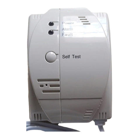
GST C-9602LW-LPG User manual


CONTENTS
IDescription...............................1
II Specification.............................1
III Structure...................................2
IV Mounting and Wiring.................3
VApplication ...............................7
VI Troubleshooting........................ 8
VII Maintenance.............................8
VIII Cautions...................................9
IX Warranty Limited .................... 10

1
I Description
C-9602LW-LPG Conventional Gas Detector
(the detector) is wall-mounted, designed to
check and monitor liquefied petroleum gas
(LPG) of leakage in such applications as
houses, hotels and apartments.
II Specification
1. Operating Voltage:187VAC~253VAC
2. Power Consumption:
Standby State≤3.0 W
Alarm State≤5.0 W
3. Output capacity and control mode:
Voltage contact: For 12VDC one-way pulse
solenoid, whose driving capability is 1000μF
capacitance discharge.
Volt-free contact: Volt-free normally open
contact, its capacity is 220V/1A used for
controlling connected devices.
4. Alarm Set Point:
Liquefied Petroleum Gas: 2200×10-6(10%LEL)
5. Indicator:
Power LED: Green, flashes in warm-up state
and then constantly lights.
Alarm/Fault LED: Dual color. It’s red when the

2
detector goes into alarm, and yellow into fault.
6. Buzzer: It sounds twice every second in
alarming, and once every three seconds in
fault.
7. Self Test: Pressing Self-Test, the LEDs will
flash in turn with the buzzer sounding three
times.
8. Life of Sensor: 5 years
9. Operating Environment:
Temperature: -10℃~ +50℃
Relative Humidity≤95%, non condensing
10.Dimension: 121mm×87mm×47mm
11.Ingress Protection Rating: IP30
12.Material and Color of Enclosure:
ABS, ivory white
13.Weight: 320g
14.Mounting Hole Distance: 23mm
III Structure
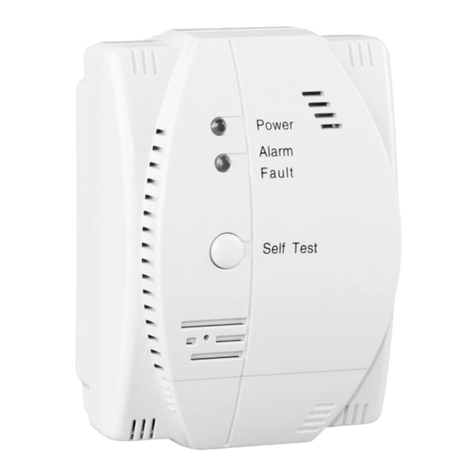
Appearance of the detector is shown in Fig.1.

3
Self Test
Alarm
Fault
Power
Sensor
87mm 47mm
121mm
Fig. 1
IV Mounting and Wiring
1. Position of Mounting
The detector is wall-mounted. Mounting
position (Fig. 2) depends on where the gas
stove is.
There are still some principles to follow.
The detector and the gas stove should be
placed in the same room.
The detector should be mounted between
30cm and 60cm above the floor.

4
1.5m<L<4m
Kitchen
Ventilator
Gas
Stove
The Detector
Floor
Ceiling
Fig. 2
The detector should be within 1.5m ~4m
to the gas source or the gas stove.
To correctly use the detector and avoid any
possible fault, please do not mount the
detector at following locations:
a. Where affected by exhaust, steam or
oil smoke from the stove.
b. Where near strong airflow, such as

5
air-inlets, fans, doors, etc.
c. Where near bathroom or places with a
lot of vapor.
d. Rooms for boiling water and places
where power is cut at night.
e. Where temperature is below -10℃or
above 50℃or outdoors.
f. Where explosion-proof measures are
required.
g. Where the detector is partitioned with
the gas devices.
2. Connecting output contacts
The cover near the bottom is opened by
pressing it with strong force. Then terminals for
connections can be seen. Those terminals are
shown in Fig. 3.
Fig. 3
K1, K2: Volt-free normally open contact, it is
closed when alarming.
V+, V-: Connects with pipe solenoid or
mechanical hand. When alarming for 3s~7s,
there is a forward 12V pulse voltage between
V+ and V-.
Put cables through the conduit under the cover,
and connect them with terminals. Note:The
conduits are located under the top cover. They

6
are not opened before leaving the factory.
Therefore, it should be opened when
connecting cables.
3. Mounting
Two mounting ways of C-9602LW-LPG
detector are shown in Fig. 4.
23
5
6
a) 将金属挂板用两个螺钉固定在墙面上;
b) 将报警器背面边缘的凹槽对准金属挂板的固定
钩,向下压入固定。
Fig. 4a
a. Hang the bracket on the wall.
b. Alignthegroovein back ofthedetectorto the
hook, press it down to fix.
5
6
6
a) 将金属挂板放在产品背面相应凹槽内(出厂已经放好);
b) 在墙上安装一个螺钉,螺钉头部露出墙面6mm左右;
c) 将挂板葫芦形挂孔挂在螺钉上即可。
Fig. 4b

7
a. Put the bracket in the groove of the detector
(by default before leaving the factory).
b. Install a screw on the wall with head about
6mm above the wall surface.
c. Hang the detector with the bracket on the
wall.
4. Wiring
0.5mm2or above Fire-resistant copper core
cable for V+ and V-.
1.0mm2or above Fire-resistant copper core
cable for K1 and K2.
V Application
1. Applying power supply to the detector
after wiring and checking, the green LED
flashes 3~6 minutes for warm-up, and then it
will light constantly for normal monitoring.
2. Alarming: When the volume ratio of
liquefied petroleum gas to be monitored is
above the alarm set point, the detector gives
quick intermittent "Tick" sound with red LED
quick flashing and K1 and K2 are closed. After
alarming for 3s~7s, the detector will output a
forward pulse current to close solenoid. When
the volume ratio of LPG goes below the alarm
set point, the detector will automatically stop
audible and visual signal and K1, K2 will be
self-opened. If, at this time, the solenoid has
been closed, it will be kept closed, and you will

8
have to pull it open manually.
3. Fire Alarm Treatment
When the detector goes into alarm, please
immediately open the windows for ventilation;
Cut gas source if there isn’t solenoid valve; Put
out any fire; do not make new fires; Avoid
switching on or off any electric appliance, find
out the reason of leaking and call professional
engineers.
VI Troubleshooting
No.
Fault
Reason
Solution
1.
Alarms
after
power-up
Hasn't been
powered for
a long time
or first time
powered up.
It will
resume
normal
after a
period.
2.
Solenoid
cannot be
switched
off
Polarity of
the solenoid
is reversed.
Wire
correctly.
VII Maintenance
1. Avoid using much hair tonic, pesticide,
paint, alcohol, diluents etc near the detector, to
avoid affecting normal monitoring of the sensor.

9
2. In case of fault, never remove or open the
detector by yourselves. Inform our company or
our local office for repair.
VIII Cautions
1. Don't install the detector at locations with
high temperature (near stoves) or too much oil
smoke (near kitchen ventilator); Keep
environment around the detector clean.
2. Please contact local gas company and ask
a professional engineer to install a solenoid
valve on the gas pipeline if it is required. The
detector can only control JJ or FCR series
solenoid coming with the detector. If other
models are to be used, please consult us.
3. The detector should be tested every half
year. The detector can be tested by a lighter.
Put the lighter near the sensor (over 10cm)
press its switch to turn it on and then blow off
the flame. The detector should go into alarm in
about 10 seconds.
4. The detector will be normal with a bit hot in
operation.
5. Never cut down the power of the detector.
6. After having been stored without power, the
detector will not work normally until it is

10
powered for a period.
IX Warranty Limited
GST warrants that the product will be free from
defects in design, materials and workmanship
during the warranty period. This warranty shall
not apply to any product that is found to have
been improperly installed or used in any way
not in accordance with the instructions supplied
with the product. Anybody, including the agents,
distributors or employees, is not in the position
to amend the contents of this warranty. Please
contact your local distributor for products not
covered by this warranty.

11
Gulf Security Technology Co., Ltd.
No. 80, Changjiang East Road, QETDZ, Qinhuangdao, Hebei,
P. R. China 066004
Tel: +86 (0) 335 8502434
Fax: +86 (0) 335 8502532
service.gst@fs.utc.com
www.gst.com.cn
Table of contents
Other GST Gas Detector manuals
Popular Gas Detector manuals by other brands

FireClass
FireClass FC410DDM Fixing instructions

Dräger
Dräger PointGard 2100 installation instructions

Critical Environment Technologies
Critical Environment Technologies LPT Series Operation manual

SENSIT Technologies
SENSIT Technologies Gas Trac LZ-30 Quick start instructions

Southern Cross
Southern Cross Flame Pack 400 Series Operation and service manual

Cosmos
Cosmos XA-440011 instruction manual