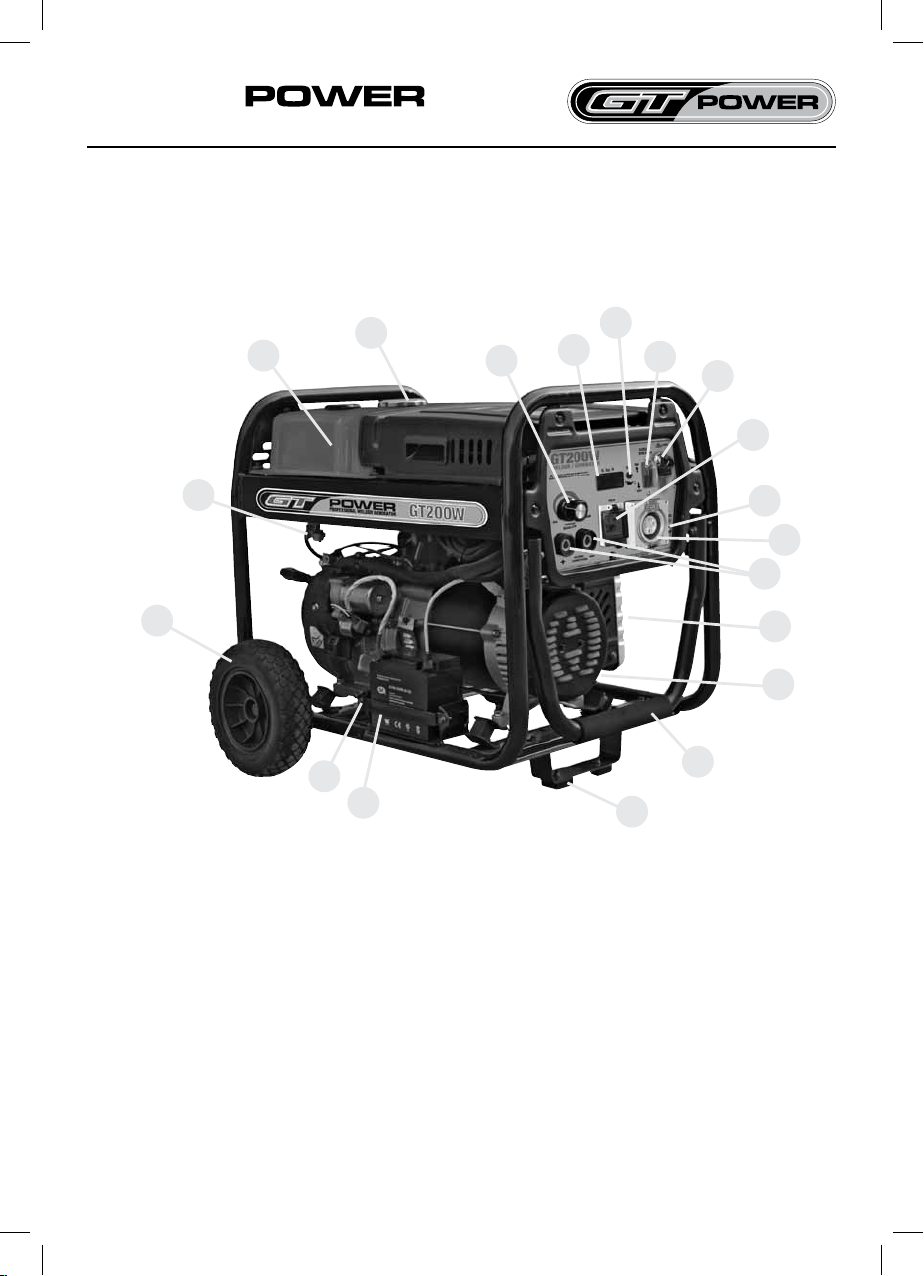
GT200W PROFESSIONAL WELDER GENERATOR
7.
www.gtpower.co.nz
WARNING: Do not attempt to use this
equipment until you have thoroughly
read all operating and maintenance
manuals supplied with your machine.
They include important safety precau-
tions, detailed engine starting, operat-
ing and maintenance instructions, and
parts lists.
Hazards of Electric Shock, Engine
Exhaust & Moving Parts
ELECTRIC SHOCK can kill.
• DO NOT touch electrically live parts
or electrode with skin or wet clothing.
• Insulate yourself from work and ground.
• Always wear dry insulating gloves.
ENGINE EXHAUST can kill.
• Use in open, well ventilated areas or vent
exhaust outside.
• Do not stack anything on or near the
engine.
MOVING PARTS can injure.
• Do not operate with doors open or guards
off.
• Stop engine before servicing.
• Keep away from moving parts.
Only qualied personnel should install, use,
or service this equipment.
Location & Ventilation
Whenever you use the GT200W, be sure
that clean cooling air can ow around the
machineʼs gasoline engine and the genera-
tor. Avoid dusty, dirty areas. Also, keep the
machine away from heat sources. Do not
place the back end of the generator any-
where near hot engine exhaust from another
machine. And of course, make sure that en-
gine exhaust is ventilated to an open, outside
area.
The GT200W must be used outdoors. Do not
set the machine in puddles or otherwise sub-
merge it in water. Such practices pose safety
hazards and cause improper operation and
corrosion of parts.
Always operate the GT200W with the case
roof on and all machine components com-
pletely assembled. This will help to protect
you from the dangers of moving parts, hot
metal surfaces, and live electrical devices.
CAUTION:
GASOLINE FUEL ONLY - Use in well
ventilated areas or vent exhaust outside
Storage
1. Store the machine in a cool, dry place
when it is not in use. Protect it from dust
and dirt. Keep it where it can not be acci-
dentally damaged from construction activ-
ities, moving vehicles and other hazards.
2. If you will be storing the machine for over
30 days, you should drain the fuel to pro-
tect fuel system and carburetor parts from
gum deposits. Empty all fuel from the tank
and run the engine until it stops from lack
of fuel.
3. You can store the machine for up to 24
months if you use a stabilising additive in
the fuel system. GT Power endorses Fuel
Set™ as the recommended brand of fuel
stabiliser to use and it is available from
your local GT Power Dealer. Mix the ad-
ditive with the fuel in the tank and run the
engine for a short time to circulate the addi-
tive through the carburetor.