98
TRANSPORTATION & STORAGE (AT WAREHOUSE)
If needed, the water heater can be transported horizontally, however do not lay nor transport the water
heater with the front side facing down (see pictogram on packaging if not removed). Do not lift or carry
using the front bottom part of the water heater. The water heater should be stored in a dry place, and at a
temperature between 32°F and 140°F.
NOTICE: Long exposure to temperatures above 140°F can cause permanent deformation of the water heater.
In case the water heater is stored without its packaging, the floor’s slope should be less than 7° to prevent the
water heater from falling over.
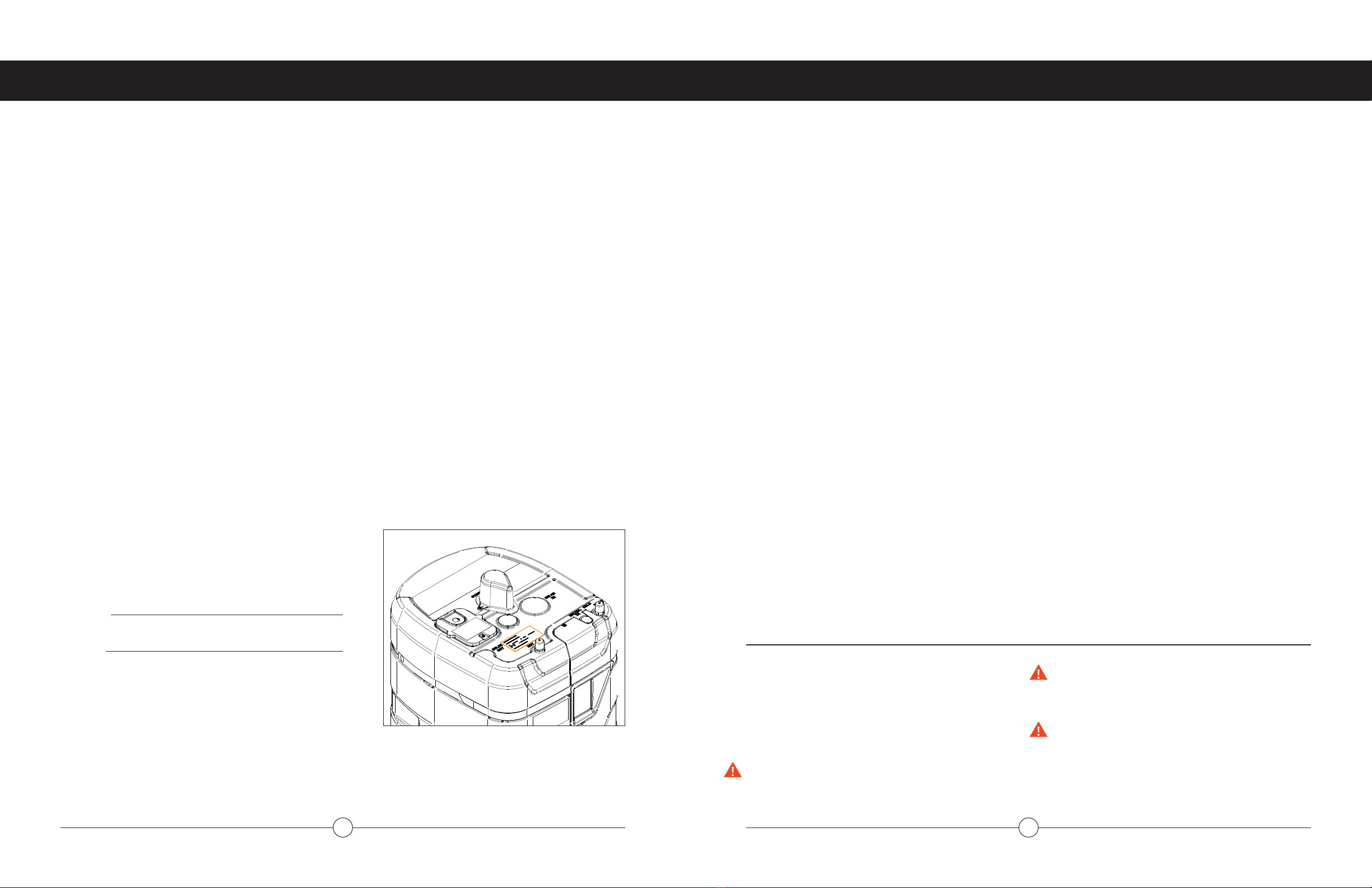
WATER QUALITY
Proper care for your water heater must include evaluation of local water quality conditions. The water
must be potable, free of corrosive chemicals, sand, dirt, and other contaminants. It is up to the installer
to ensure the water fed to the heater does not contain corrosive chemicals or elements that can aect
operation or damage the heat exchanger. Refer to the table below for the maximum allowable limits of
specific parameters according to the EPA in the Code of Federal Regulations. The installer is responsible for
understanding local conditions pertaining to these and other parameters and treating the water as necessary.
Replacement of the heat exchanger and other components due to damage caused by water quality is not
covered by the warranty.
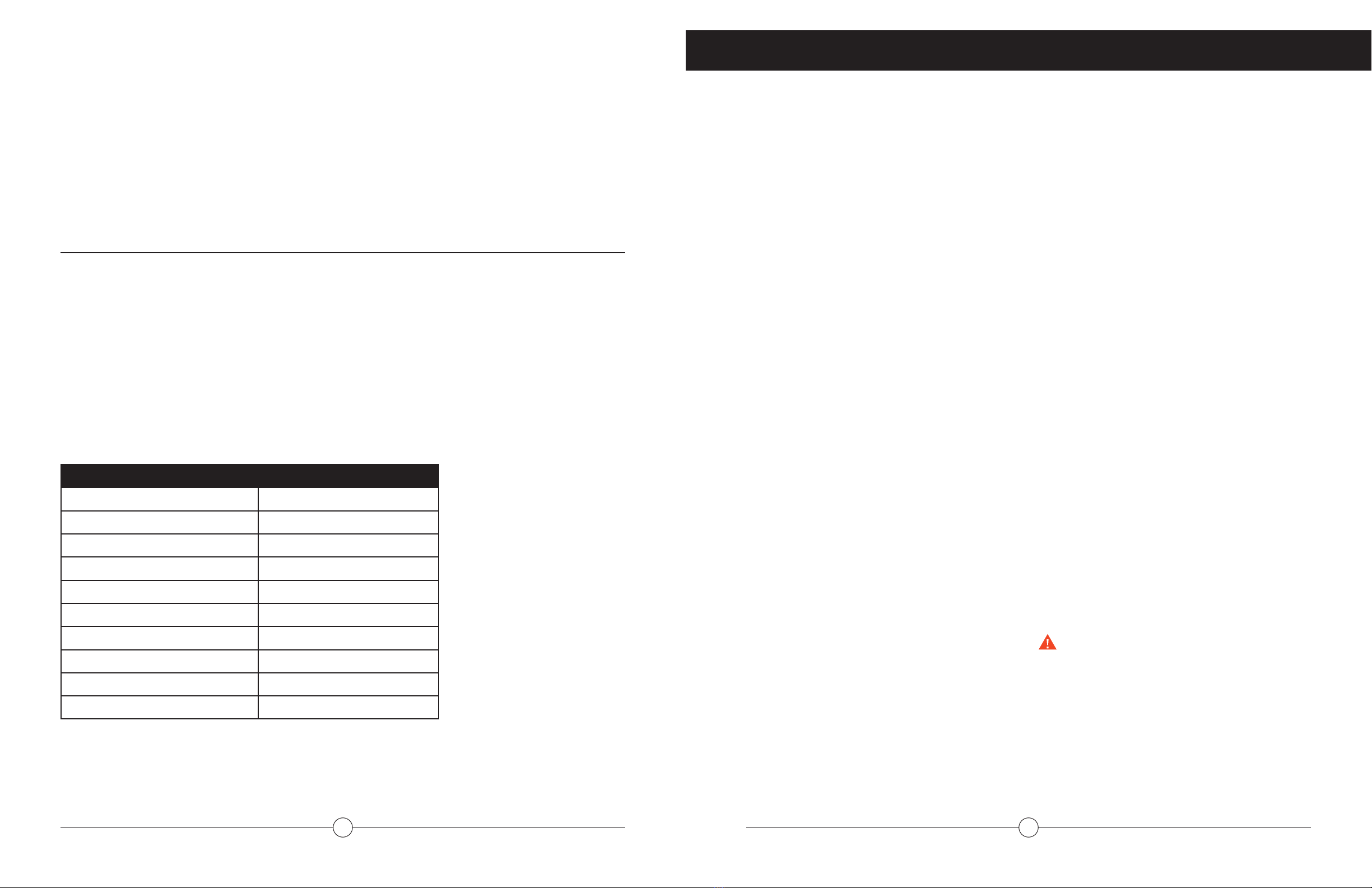
MAXIMUM LEVEL
Total Hardness Up to 200 mg / L
Aluminum * Up to 0.2 mg / L
Chlorides * Up to 250 mg / L
Copper * Up to 1.0 mg / L
Dissolved Carbon Dioxide (CO2) Up to 15.0 mg / L
Iron * Up to 0.3 mg / L
Manganese * Up to 0.05 mg / L
pH * 6.5 to 8.5
TDS (Total Dissolved Solids) * Up to 500 mg / L
Zinc * Up to 5 mg / L
* Source: Part 143 National Secondary Drinking Water Regulations
WATER SUPPLY PRESSURE
Minimum Water Pressure: 50 PSI (Recommended
60-80 PSI for maximum performance)
Maximum Water Pressure: 150 PSI
When choosing the location of the water heater,
please take into consideration the following
recommendations.
(Disregarding these recommendations will void the
warranty)
LOCAL INSTALLATION REGULATIONS
This water heater must be installed in accordance with
these instructions, local codes, utility codes, utility
company requirements or, in the absence of local
codes, the latest edition of the National Electrical
Code, which can be found in some local libraries or
can be purchased from the National Fire Protection
Association (website link: https://nfpa.org/).
NOTICE: Please be aware that installation of the
water heater in attics in regions where the outside
air temperature is commonly above 105°F (and
therefore attic temperature can be greater than
140°F) could aect the life of your water heater
electronic controls.
INSTALLATIONS IN CALIFORNIA
Seismic Provisions Water heaters shall be anchored
or strapped to resist horizontal displacement due
to earthquake motion. Strapping shall be at points
within the upper one-third (1/3) and lower one-
third (1/3) of its vertical dimensions. At the lower
point, a minimum distance of four (4) inches shall
be maintained above the controls with the strapping.
Do not obstruct any access panels.
LOCATION & WATER
HEATER CLEARANCE
Locate the water heater in a clean dry area as near
as practical to the area of greatest heated water
demand. Long uninsulated hot water lines can waste
energy and water.
Place the water heater in such a manner that the
electric junction box, the overflow line cover, the
upper element cover and the lower access panel can
be removed to permit inspection and servicing such
as removal of elements or checking controls.
The water heater and water lines should be
protected from freezing temperatures.
To allow easy access for operation and maintenance,
we recommend leaving the following clearances
around the water heater: At the front and above
the water heater: 25’’. Left and right: 4''. Back: 2''
provided that the overflow line can be correctly
installed. In case of any doubt, please check your
local codes.
DO NOT install the water heater OUTDOORS. To
ensure its long life, your water heater MUST be
installed indoors.
Never switch o the water heater. If the water
heater is not going to be used for a period of time
please use the “vacation” temporary function. This
will help to avoid damage caused by freezing.
If the water heater is not going to be used for an
extended period of time, and the electric power will
be shut o, drain your water heater completely (see
page 32).
Make certain the floor underneath the water heater
is strong enough to suciently support the weight
of the water heater once it is filled with water.
CAUTION! The water heater should not be
located in an area where leakage of the tank
or connections will result in damage to the
area adjacent to it or to lower floors of the
structure. Where such areas cannot be avoided,
it is recommended that a suitable drain pan,
adequately drained, be installed under the
water heater (See illustration on following page).
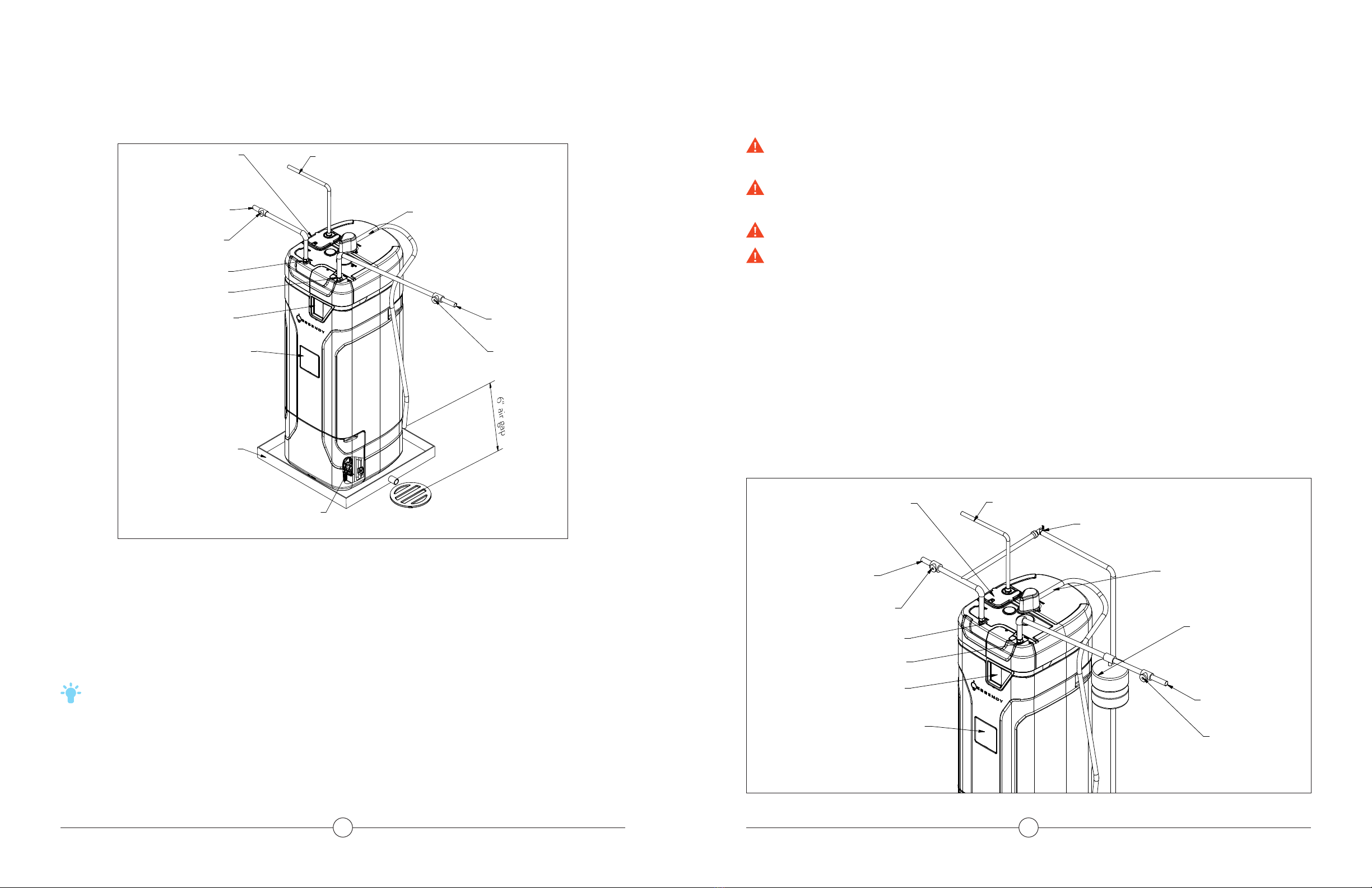
INSTALLING THE WATER HEATER


 Operation and maintenance instructions")