GTC GTC505 User manual

User’s Manual
ENGINE IGNITION ANALYZER
General Technologies Corp.

Table of Contents
1. Safety Rules Page 1
2. Technical Specications Page 2
2.1 Generalspecications Page2
2.2 Electricalspecications Page2
3. General description Page 3
3.1 Instrumentdescription Page3
3.2Displaydescription Page3
4. Buttons, icons and menus operation Page 4
4.1POWER/CLEARbuttonandmenu Page4
4.2CYCLEbuttonandmenu Page4
4.3 MODEbuttonandmenu Page5
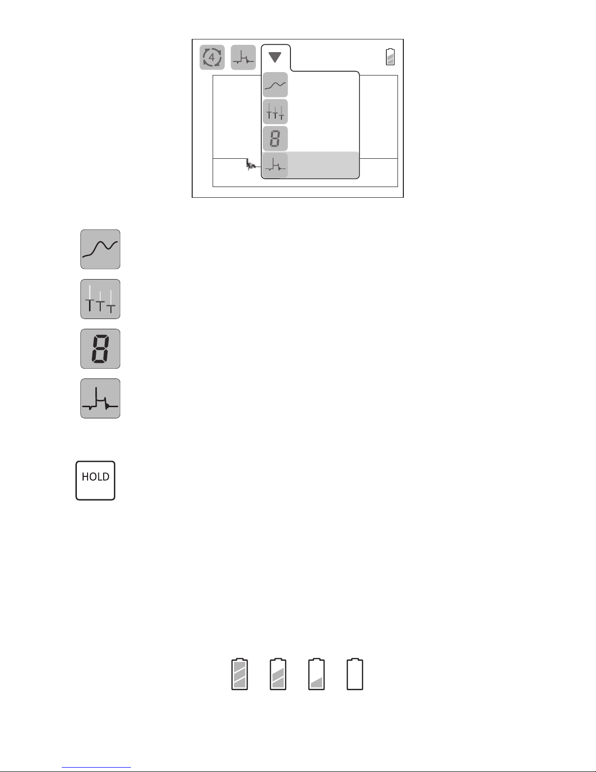
4.4VIEWbuttonandmenu Page5
4.5HOLDbuttonandmenu Page6
4.6Tachometerreadings Page6
4.7Batterylevelindicator Page6
5. Measurement modes Page 7
5.1EngineRPM Page7
5.2Sparkburn(ring)time Page7
5.3 Sparkplugvoltage Page7
5.4Dwellangle Page7
5.5Ramptime Page7
6. Display views Page 8
6.1Chartview Page8
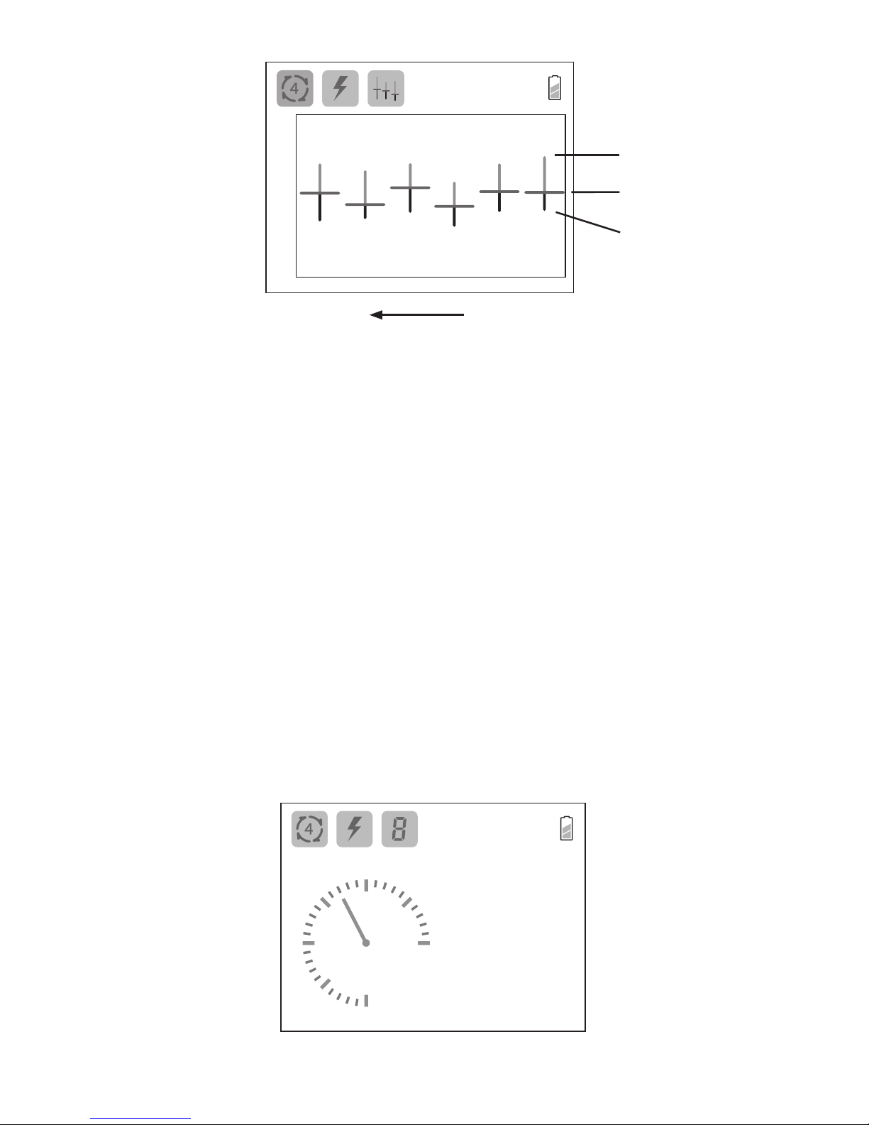
6.2Comparisonview Page8
6.3 Digitalview Page9
6.4WaveformView Page10
7. Measurement procedures Page 10
7.1Flexibleprobeandsensorsetup(GTC505andGTC505m) Page11
7.2Extensioncableandsensorsetup(GTC505monly) Page11
7.3Measuringcoilonplugandcoilnearplugignitionsystems Page11
7.4Measuringignitionsystemswithsparkplugwires Page12
8. Recharging the instrument Page 13
9. Maintenance Page 14
10. Warranty Page 14
1. SAFETY RULES
•Thisinstrumentisdesignedforindooruseattemperaturesbetween32°and104°F(0°Cand
40°C)andaltitudesupto6500ft.(2,000meters).
• Toensurethattheinstrumentisusedsafely,followallsafetyandoperatinginstructionsinthis
operationmanual.Iftheinstrumentisnotusedasdescribedinthisuser’smanual,thesafety
featuresofthisinstrumentmaybeimpaired.
• Donotusetheinstrumentiftheinstrument,thesensors,ortheexibleprobelookdamaged,
orifyoususpectthattheinstrumentisnotoperatingproperly.
• Whenusingtheinstrument,keepawayfrommovingparts(fan,drivebelts,etc)andhotobjects
(exhaustpipes,mufer,catalyticconverter,etc),toavoidpersonalinjuriesanddamagetothe
instrument,thesensors,exibleprobeandextensioncable..
• Donotconnecttheinstumenttoanythingotherthanthesensors,exibleprobe,extension
cable,USBcable,orACpoweradapterprovided.
• Atalltimes,toavoidelectricalshock,useCAUTIONwhenworkingwithelectricalcircuitsabove
60VDCor25VACrms.Suchvoltagesposeashockhazard.
• DonotoperatethisinstrumentwhileconnectedtotheACpoweradaptororanyotherdevice.
• Toavoidelectricalshockordamagetotheinstrument,donotexceedthespeciedinputlimits.
Exceeding the limits listed above when using this apparatus, or not observing the
precautions listed above can expose you to physical injury and permanently damage
your instrument and/or parts and components of the vehicle under test.

Page2
2. TECHNICAL SPECIFICATIONS
2.1 General specications
Display: 3.5”TFTLCD,320x240pixelsresolution.
Framerate: Upto30timespersecond.
Ignitionsystemtype: Coilonplug,coilnearplug,DIS,wastespark,conventional,
andmagneto.
Enginecycle: 2or4strokes.
Power(internal): 3.2volt/1500mAh,rechargeableLiFePO4battery.
Autopoweroff: Automaticallypowersoffafter3min.ofinactivity.
Batterylife: Approximately6hoursofcontinuousoperation.
USBconnector(input): MicroUSB(5Volt/0.5AmperesDC).
Probelength: 13.5”(34cm)includingsensor.
Dimensions: 6.3”x3.9”x1.3”(160x99x34mm)withoutprobe.
Weight: Approximately14oz.or406gwithoutprobe.
Includedaccessories: Sparkplugwiresensor,coilonplugsensor,BNCexibleprobe,
protective rubber holster, padded hard carrying case, micro
USBcable,ACpoweradaptor,anduser’smanual.Themodel
GTC505malsoincludesa78”(2m)extensioncableandaclip-on
sparkplugwiresensor.
2.2 Electrical Specications
•Thespecicationsbelowaretypicalat23°C,andwillvaryslightlyfromdevicetodevice,
and with temperature.The input voltage should not exceed the indicated maximum
values,topreventpersonalinjuryordamagetotheinstrument.
MeasurementMode MeasurementRange Accuracy/Resolution
Tachometer
400to19999RPM
2or4strokeandwastespark Accuracy:0.5%±1LSD
Sparkplugvoltage 0to50kV Resolution:±0.01kV
Sparkburn(ring)time 0to12ms Resolution±0.05ms
Dwellangle 0to>270°(4stroke/600RPM+)
0to>180°(2stroke/750RPM+) Resolution:±0.1º
Ramptime(ignitioncoil
primarycurrentramptime) 0to35ms Resolution:±0.05ms

Page3
3. GENERAL DESCRIPTION
3.1 Instrument description
3.2 Display description
Fig.1-Instrumentdescription
Fig.2-LCDDisplay
01607 RPM
-10
10
20
kv
-4 -2 0 2 ms
0
Enginecycle
setting
Mode
setting
Display
setting
Tachometer
reading
Battery
level
Statusindicators
Measurement
displayarea
MicroUSBconnector
LCDdisplay
POWER/CLEARbutton
CYCLEbutton
MODEbutton
BNCconnector
Protectivehoster
HOLDbutton
VIEWbutton

Page4
4. BUTTONS, ICONS AND MENUS OPERATION
4.1 ‘POWER/CLEAR’ button
•WhentheinstrumentisOFF,toturnitONpressandholdthe‘POWER/CLEAR’
buttonuntiltheunitturnson(inapproximately1second).
•WhentheinstrumentisON,toturnitOFFpressandholdthe“POWER/CLEAR’
buttonuntilthedisplayturnsOFF(inapproximately3seconds).
•When the instrument is ON, press the ‘POWER/CLEAR’ button to clear all
measurementdata,andstartanewmeasurement.Thisoperationcanbealso
beperformedtore-scalethemeasurementsandoptimizeviewinginthedisplay.
•The‘AutoPowerOff’featurewillautomatically turnthe instrumentoffafter3
minutesofnobuttonbeingpressedor15secondsafterthelastsparksignalwas
detected.Turningtheunitoffmanuallywhennotinusewillprolongbatterylife.
4.2 ‘CYCLE’ button and menu
•The‘CYCLE’buttonallowsselectionofthenumberofstrokescorrespondingto
theengineundermeasurement.Uponpressingthisbutton,apulldownmenu
willopenwiththecurrentsettinghighlighted,Tochangethesettingpressthe
‘CYCLE’buttonrepeatedlyuntilthecorrectsettingishighlighted,thenwaituntil
thepulldownmenucloses.Thenewsettingwillbedisplayedasthecycleicon
atthetopofthescreen.
01607 RPM
-5-4 -2 0 2 ms
0
4
2
4 Stroke
2 Stroke
Waste Spark
Fig.3-Enginecycleselectionmenu
2strokeenginecycle
4strokeenginecycle
DISorwastesparkignitionsystem

Page5
4.3 ‘MODE’ button and menu
The ‘MODE’ button allows the selection of the type of measurement to be
showninthedisplay.Uponpressingthisbuttonapulldownmenuwillopenwith
thecurrentsettinghighlighted,Tochangethesettingpressthe‘MODE’button
repeatedlyuntilthedesiredsettingishighlighted,thenwaituntilthepulldown
menucloses.Thenewcurrentsettingwillbedisplayedasthemodeiconatthe
topofthescreen.
01607 RPM
-5
5
10
kv
-4 -2 0 2 ms
0
Burn Time
Dwell
Tachometer
Voltage
Fig.4-Measurementmodeselectionmenu
Measuring/displayingsparkburn(ring)time.
Measuring/displayingdwellangleorramptime(automaticallyselected
dependingontheconnectedsensor).
Measuring/displayingRPM(tachometer).
Measuring/displayingsparkplugvoltages.
4.4 ‘VIEW’ button and menu
The’VIEW’buttonisusedtoselecthowthechosenmeasurementwillbe
showninthedisplay.Uponpressingthisbuttonapulldownmenuwillopen
withthecurrentsettinghighlighted.Tochangethesettingpressthe‘VIEW’
buttonrepeatedlyuntilthedesiredsettingishighlighted,thenwaituntil
thepulldownmenucloses.Thenewsettingwillbedisplayedasthedisplay
iconatthetopofthescreen.

Page6
01607 RPM
-10
10
20
kv
-4 -2 0 2 ms
0
Chart
Comparison
Digital
Waveform
Fig.5-Displaymodeselectionmenu
Chart(i.e.trendline)view.
Comparisonview.
Analoggaugeanddigitalreadouts
Waveform(i.e.oscilloscope)view.
4.5 ‘HOLD” button
· Whenchart,digitalorwaveformdisplaymodeisselected,pressingthe‘HOLD’
buttonwillpausethemeasurement,holdthecurrentdisplay,andtheword
“HOLD”willbeshowninthemeasurementareaofthedisplaytoindicatethis
status.Pressthe‘HOLD’buttonagaintoresumenormaloperation.
· Wheninthecomparisondisplaymode,thisbuttonisusedtoinitiateandstopa
measurement.Fordetailssee‘6.2Comparisonview’.
4.6 Tachometer reading
DigitalreadoutoftheengineRPM.
4.7 Battery level indicator
Thebatterylevelindicatorprovidesanapproximateindicationofthestateofchargeof
theinternalbattery,asfollows:
Full
Empty
NOTE: Theinstrumentwillturnautomaticallyoffifthebatteryvoltagefallsbelowthe
absoluteminimum.

Page7
5. MEASURING MODES
Therearefourdifferentignitionsystemparametersthatcanbeselectedformeasurement,
dependingontheengine’signitionsystem:
•EngineRPM.
•Sparkburn(ring)time.
•Sparkplugvoltage.
•Dwellangles(forignitionsystemsequippedwithhighvoltagesparkplugwires).
• Primaryignitioncoilcurrentramptime(forcoilonplugandcoilnearplugignitionsystems).
5.1 Engine RPM
MeasuresengineRPM(revolutionsperminute)in2and4strokeengines,andmaybe
usedincombinationwithothermeasurementstoevaluateignitionsystem
performanceatdifferentenginespeeds.
5.2 Spark burn (ring) time
The spark burn time, also called “ring time”, is the measurement of the period from
themomentasparkisinitiateduptothepointwhenitisextinguished,andisthemost
indicativemeasurementofperformanceoftheignitionsystem.Abnormallylongorshort
burntimesmayindicatesomeproblemintheignitionmodule,sparkplug,fuelmixture,
cylindercompression,etc.
5.3 Spark plug voltage
Sparkplugvoltagevaluesareusefulforcomparingtheperformanceoftheignitionsystem
betweencylinders.Thismaybeusedtodiagnosecommonproblemslikemisres,broken
sparkplugwires,etc.Sparkplugpeakvoltagesmayvarywidely,arelessconsistentand
notalwaysindicativeofaproperlyworkingignitionsystem.Ontheotherhand,observation
ofthesparkplugvoltagewaveformortrendmayproveusefulindiagnosingignitionand
mechanicalproblems.
5.4 Dwell angle (for ignition systems using spark plug wires only)
Dwellangleisameasurementoftheangleofrotationofthecrankshaft,betweenthemoment
inwhichtheprimaryoftheignitioncoilisenergized(e.g.pointcontactsclosed)andthe
sparkisgenerated(e.g.pointcontactsopened).Itsmainuseisindeterminingifthereis
enoughangle(ortime)toenergizetheprimaryoftheignition,andnotsomuchastocause
theignitioncoiltooverheatandfail.Dwellanglesarespeciedforaparticularengineand
RPM,andusuallyadjustedinthemechanicaldistributor/pointassembly.
5.5 Current ramp time (for coil on plug and coil near plug only)
Ramp time is measured from when the primary coil current rst begins to increase to
whenitstopsincreasing.Thecurrentmaystopincreasingbecausethecoilhasreached
itssaturationpoint,oritisinterruptedtogenerateaspark.
Ramp time measurements are useful for diagnosing problems in the primary circuit of
theignitionmodule.Abnormallylongramptimesmayindicateexcessiveprimarycircuit
resistance,lowinputvoltage,thatthewrongmoduleisinstalled,etc.Shorterthannormal
ramptimesmayindicateashortedprimarycoil,thatthewrongmoduleisinstalled,etc.

Page8
6. DISPLAY VIEWS
Therearefourviewsthatcanbeselectedtodisplaymeasurements:
•Chart
•Comparison
•Digital
•Waveform
6.1 Chart view
Thisviewdisplaystheselectedmeasurement’svaluecorrespondingtoeachofthelast276
sparks,withtheleftmostmeasurementbeingtheoldest,andtherightmostthenewest.The
measurementscaleandunitsarelocatedontheverticalaxis,atthefarleftofthedisplay.
0S
2
3
RPM
1
01607 RPM
Fig6-Chartviewdisplay
•‘POWER/CLEAR’ button:
PressingthePower/Clearbuttonclearsallvaluesfromthechart,andre-scalesthe
chartifnecessary.
•‘MODE’ button:
Pressingthe‘MODE’buttononcewillopenthemodemenu,andhighlightthemeasurement
modecurrentlyselected;pressingthe‘MODE’buttonagainwhilethemenuisopenwill
selectthenextavailablemeasurementmode.Allfourmeasurements(sparkburntime,
RPM,sparkplugpeakvoltage,anddwellangleorramptime)aresimultaneouslytracked
andstored,andareavailableforviewingatanytime(withoutdelay).
•‘HOLD’ button:
Pressingthisbuttonwillpausethemeasurement,andholdthedisplayinitsthecurrent
condition.Pressingthe‘HOLD’buttonagainwillresumenormalmeasurement.
6.2 Comparison view
This mode allows the comparison of sets of values (minimum, average and maximum
measurements) between several cylinders, under various testing conditions, or other
situations.Themeasurementsaredisplayedfromlefttoright,withtheleftmostsetof
valuesbeingtheoldest,andtherightmostthenewest.Anewsetofvaluesisaddedevery
timethe‘HOLD’buttonispressedtwice(stop/start)anduptothelast16setsofvalueswill
beshowninthegraphatonce,ifthismaximumisexceeded,theoldestsetwillbedeleted
andanewsetadded.Themeasurementscaleandunitsarelocatedontheverticalaxis,
atthefarleftofthedisplay.

Page9
0
10
15
kv
5
01607
RPM
Maximum
Average
Minimum
Oldestset Newestset
Fig.7-Comparisonmodedisplay
•‘POWER/CLEAR’ button:
Pressingthe‘POWER/CLEAR’buttonclearsallmeasurements,andre-scalesthechart
ifnecessary.
•‘MODE’ button:
Pressingthe‘MODE’buttononcewillopenthemodemenu,andhighlightthemeasurement
modecurrentlyselected;pressingthe‘MODE’buttonagainwhilethemenuisopenwill
selectthenextavailablemeasurementmode.Allfourmeasurements(sparkburntime,
RPM,sparkplugpeakvoltageanddwellangleandramptime)aresimultaneouslytracked
andstored,andareavailableforviewingatanytime(withoutdelay).
•‘HOLD’ button:
The‘HOLD’buttonwhenpressedoncepausesmeasurementandholdsthedisplay
initscurrentcondition(whiledisplayinga“HOLD”labelinthecenterofthescreen).
Pressingthe‘HOLD’buttonasecondtimewillremovethepause(andlabel),andadd
anewsetofvaluesattherightofthescreen,whichwillkeepupdatinguntilthe‘HOLD’
buttonispressedagain.Thiscyclerepeatseverytimethebuttonispressedtwice(stop/
start)anduptothelast16setofvalueswillbeshowninthedisplayatonce,ifthis
maximumisexceededtheoldestsetwillbedeletedandanewsetadded.
6.3 Digital view
Thisviewprovidesanaloggaugeanddigitalreadoutsfortheselectedmeasurement,as
wellasdigitalreadoutsforthethreeothermeasurements.
7.14MAX
5.20
6.71
MIN
kV
0
2
4
6
8
10
12
01607 RPM
PEAK
Fig.8-Digitalmodedisplay

•‘POWER/CLEAR’ button:
Pressingthe‘POWER/CLEAR’buttonclearsalldigitalreadoutvalues,andre-scales
thegaugeifnecessary.
•‘MODE’ button:
Pressingthe‘MODE’buttononcewillopenthemodemenu,andhighlightthemeasurement
modecurrentlyselected;pressingthe‘MODE’buttonagainwhilethemenuisopenwill
selectthenextavailablemeasurementmode.Allfourmeasurements(sparkburntime,
RPM,sparkplugpeakvoltageanddwellangleandramptime)aresimultaneouslytracked
andstored,andareavailableforviewingatanytime(withoutdelay).
•‘HOLD’ button:
Pressing this button will pause measurement, and hold the display in the current
condition.Pressingthe‘HOLD’buttonagainwillresumenormalmeasurements.
6.4 Waveform view
Thismodedisplaysthesignalamplitudeovertime(likeanoscilloscope).Thescaleand
unitsofthemeasurementarelocatedontheverticalaxis,atthefarleftofthedisplay.The
timescaleandunitsareshownbelowthehorizontalaxis,atthebottomofthescreen.
01607
RPM
-10
10
20
kv
-4 -2 0 2 ms
0
Fig.9-Waveformdisplay
•‘POWER/CLEAR’ button:
Pressingthe‘POWER/CLEAR’buttonclearsthegraph,andre-scalesifnecessary.
•‘MODE’ button:
Pressing the ‘MODE’ button once will open the mode menu, and highlight the
measurementmodecurrentlyselected;pressingthe‘MODE’buttonagainwhilethe
menuisopenwillselectthenextavailablemeasurementmode.Thewaveformgraph
focusesontheareaofthesparkwaveformwhichismostrelevanttothemodeselected.
•‘HOLD’ button:
Pressingthisbuttonwillpausethecurrentmeasurement,andholdthedisplayinthe
currentcondition.Pressingthe‘HOLD’buttonagainwillresumenormalmeasurement.
7. MEASUREMENT PROCEDURES
Page10
CAUTION
Toavoidpersonalinjuriesanddamagetotheinstrumentcarefullyinspectthesparkplug
wires,distributorcap,ignitioncoil,ignitionmodulesandallotherignitionsystempartsfor
damageorleaks,andavoidusingtheinstrumentincaseanydamageorleaksarefound.
Nevertouchthesensor,exibleprobeorcableduringatest.Wearinsulatinggloveswhen
workingaroundhighvoltageandhotparts,andkeepawayfrommovingparts(fan,drive
belts,etc.)andhotobjects(exhaustmanifoldandpipes,mufer,catalyticconverter,etc.).

Theinstrumentwillautomaticallydetectandcongureaccordingtothesensorconnected
tothe probe or extension cable. Using thewrongsensorfor the ignition system under
measurementmayleadtoerroneousreadings,ornoreadingsatall.
7.1 Flexible probe and sensor setup (GTC505 and GTC505m)
Thisinstrumentissuppliedwithaexibleprobe,andtwotypesofsensors:
• Flexibleprobe:equippedwithaBNCconnectoratoneendandabarrelconnectorattheother.
• COPsensor:formeasuringcoilonplugandcoilnearplugignitionsystems.
• SPWsensor:forallignitionsystemswhichusehighvoltagewires(sparkplugwires)to
connecttheignitioncoilordistributortothesparkplug.
COPsensor SPWsensor
Flexibleprobe
Fig.10-Sensorsconnectiontoexibleprobe
1-ConnecttheprobetotheinstrumentusingtheirBNCconnectors.
2-InsertandrmlypresstheappropriateCOPorSPWsensorintothebarrelconnector
oftheprobe.
7.2 Extension cable and sensor setup (GTC505m only)
TheGTC505misalsosuppliedwithaextensioncableandclip-onsparkplugwiresensor
toallowforremotemeasurements:
• Extension cable: 78” (2 m) equipped with a BNC connector at one end and a barrel
connectorattheother.ThisextensioncablecanbeusedwithCOP,SPWandtheclip-on
SPWsensor.
• Clip-onSPWsensor:forallignitionsystemswhichusehighvoltagewires(sparkplug
wires)toconnecttheignitioncoilordistributortothesparkplug.
Fig.11-Sensorsconnectiontoextensioncable
1-ConnecttheextensioncabletotheinstrumentusingtheirBNCconnectors.
2-Insertandrmlypress theappropriateCOPorclip-onSPWsensor intothebarrel
connectoroftheextensioncable.
7.3 Measuring coil on plug and coil near plug ignition systems
1-Ensuretheinstrumentisturnedoff.
2-InserttheCOPsensorbarrelconnectorplugintotheexibleprobereceptacle,removing
theSPWsensorifnecessary.
Page11
COPsensor Clip-onSPWsensor
Extensioncable

3- Turn the instrument on and select the appropriate cycle for the engine under
measurement.
4-Selectthedesiredmodeandview.
5- PlacetheCOPsensoronthetopandcenteroftheignitionmodule(asshowninthe
Fig.12),andobservewhethertheinstrumentisabletodetectanddisplaythedesired
measurement.
Fig.12-UsingtheCOPsensoronaignitionmodule
6-Iftheinstrumentisunabletodetecttheignitionsystemsignal,itmaybenecessaryto
repositionthesensorsothataconsistentsignalisdetectedanddisplayed.
NOTES
• The position of the sensor and the particular design of the ignition module may
affect the signal’s shape shown when the waveform display is selected. In order to
comparewaveformsbetweenseveralcylinders’ignitionmodules,theplacementofthe
sensorrelativetotheignitionmoduleshouldbekeptasconsistentaspossibleforallthe
measurements.
•In some engines, the ignition modules are located very close together, and in rare
occasionsthiscouldcausetheinstrument’ssensortodetectsignalsfromnearbymodules,
leading to inconsistent measurements. This can usually be solved by changing the
placementororientationofthesensorontheignitionmodule.
7.4 Measuring ignition systems with (high voltage) spark plug wires
1-Ensuretheinstrumentisturnedoff.
2-InserttheSPWorClip-onSPWsensorbarrelconnectorplugintotheexibleprobeor
extensioncablereceptacle.
3-Turn the instrument on, and select the appropriate cycle for the engine under
measurement.
4-Selectthedesiredmodeandview.
5-IfusingtheSPWsensor,placethesparkplugwireintotheslotofthesensor,andasfar
aspossiblefromothersparkplugwirestryingtomaintainarightangle(90°)between
thesensorandthewire.
SparkplugwireSPWsensor
Fig.13-UsingtheSPWsensoronasparkplugwire
Page12
COPsensor Ignitionmodule

Page13
6-Ifusingtheclip-onSPWsensor,placethesparkplugwireintotheslotofthesensor,
as far as possible from other spark plug wires, and turn the body clockwise 60° to
lock the sensor on the spark plug wire. To unlock, turn the body of the sensor 60°
counterclockwise.
Fig.14-Usingtheclip-onSPWsensoronasparkplugwire
7-Iftheinstrumentisunabletodetecttheignitionsystemsignal,itmaybenecessaryto
repositionthesensorsothataconsistentsignalisdetectedanddisplayed.
NOTES
• Theabsolutesparkplugvoltagereadingwilldependonthepositionofthesensor,the
particularcharacteristicsofthewire,etc..Thereforetheplacementofthesensorrelative
tothewireshouldbekeepasconsistentaspossibleforallthemeasurementsinorder
tocomparevoltagereadingsbetweenseveralcylinders’sparkplugwires.
•Sparkburntime,dwellangleandRPMmeasurementsarenotsensitivetotheexact
positionofthesensorrelativetothesparkplugwire,butthesensormustbepositioned
sotheinstrumentiscapableofdetectingthesignal.
• When several spark plug wires are routed or bunched close together, the
capacitivesensormayreceivesignalsfromtwoormorewiressimultaneously,which
couldcauseerroneousmeasurements.Inthesesituationsitisnecessarytoseparate
thewireundermeasurementfromtheothers,inordertoreduceinterferenceandobtain
anaccuratemeasurement.
8. RECHARGING THE INSTRUMENT
1-Ifstilloperating,turntheinstrumentpoweroff.
2-Locateandlifttherubbercap(attachedtotheprotectiveholsterandlocatedbesides
theBNCconnector)torevealthemicroUSBreceptacle.
BNCConnector MicroUSBconnectorcap
Fig.15-Instrument’sconnectors
1 2

Page14
3-InserttheUSBchargercable’smicroUSBplugintothereceptacleoftheinstrument
matchingtheorientationoftheconnectors.
4-InserttheUSBtypeAconnectorofthecableintotheUSBportofthesuppliedUSB
powerchargeradapter,andplugthepoweradapterintoanACpoweroutlet.
5-Uponstartofchargingthebattery,thedisplaywillshowthecharginginprogressicon
andthescreenwillturnoffafterafewseconds.
CharginginprogressChargingcomplete
Fig.16-Chargingindicators
6-Iftheinstrumentisturnedon(bypressingthe‘POWER/CLEAR’button)atanytime
whileconnectedtothepoweradapter,theinstrumentwilldisplaythechargingstatus.
7-TheUSBtypeAconnectorcanbealsopluggedintoaUSBportofapersonalcomputer,
poweredUSBhub,oranyotherUSBcompliantpowersource.
5-Therechargetimewilldependonthestateofchargeofthebattery,anditmaytakeup
to6hourstofullyrechargeadepletedbattery.
NOTES
•If the instrument has not been used for a long time, or the state of charge of the
batteryhasfallentoacriticallylowlevel,aperiodofpre-conditioningofthebatteryis
automaticallyaddedtothenormalchargingcycle,whichincreasesthechargingtime
inordertorestorethebatterycapacitytoitsmaximum,Nouserinterventionisneeded,
andthisprocessisautomaticallycarriedoutbytheinstrument.
•Ifthe battery iscompletely depleted, pressing thepower on buttonwillnot turn the
instrumenton,anditmustberechargedbeforeitcanbeusedagain.
9. MAINTENANCE
Keeptheinstrumentinitscarryingcasewhennotinuseanddonotsubjectittodampness,
severeheatorcold.Donotusetheinstrumentintherain;ifitshouldaccidentallygetwet,
dryitoffwithacleanpapertowelbeforestoringitaway.
Protecttheunitfromcontactwithanysolvents.Nevercleanwithasolventorpetroleum
basedmedium such as gasoline, as these chemicals may attack the plastic partsand
causepermanentdamage.Neveruseanabrasivecleaner.Cleaningshouldbelimitedto
wipingwithacleandamppapertowelandasmallamountofsoapifrequired.Drytheunit
thoroughlyafteranycleaning.
The unit is a sealed instrument, and contains no user serviceable parts. Opening this
instrumentwillvoidthewarranty.
10. WARRANTY
Thisinstrumentcarriesaone(1)yearwarranty(fromthedateofpurchasebytheoriginal
owner)againstdefectsofmaterialorworkmanship.FordetailsseeourStandardWarranty
Informationonourwebpageatwww.gtc.ca,orrequestaprintedcopy.

Part#GTC505MN1707EN
©2016-2017GeneralTechnologiesCorp.
PrintedinCanada
#121-735072ndStreetTel:(604)952-6699
Delta,BC Fax:(604)952-6690
CanadaV4G1H9 email:[email protected]
“SmarTach”,“VReady”,“GTC505”and“GTC”aretrademarksofGeneralTechnologiesCorp.
Tovisitourwebsite,scantheQRcodebelowwithyoursmartphone.
OrtypethisURLinyourbrowser:
www.gtc.ca
This manual suits for next models
1
Table of contents
Other GTC Measuring Instrument manuals
Popular Measuring Instrument manuals by other brands

Endress+Hauser
Endress+Hauser Proline Promag 50P technical information

ETM
ETM ETM770-IoT user guide

Ryobi
Ryobi RP4000 Operator's manual

Veeder-Root
Veeder-Root EMR4 PC Setup Quick Help Guide

TT electronics
TT electronics SGUV MK.2 OPERATION & MAINTENACE MANUAL

TechnipFMC
TechnipFMC Proline Promass E 500 Operating instructions manual