VIRTINS VT RTA-268A User manual

VT RTA-268A/B/C Manual Rev. 1.5
www.virtins.com 1 Copyright © 2010-2023 Virtins Technology
Virtins Technology
VT RTA-268A/B/C Manual
An Ultra Low-Noise Real Time Acoustic Analyzer, Sound Level Meter,
Distortion Analyzer, Polarity Tester, Time Delay Finder …
Note: VIRTINS TECHNOLOGY reserves the right to make modifications to this manual at any time without
notice. This manual may contain typographical errors.

VT RTA-268A/B/C Manual Rev. 1.5
www.virtins.com 2 Copyright © 2010-2023 Virtins Technology
Virtins Technology
TABLE OF CONTENTS
1 INSTALLATION AND QUICK START GUIDE..........................................................................................3
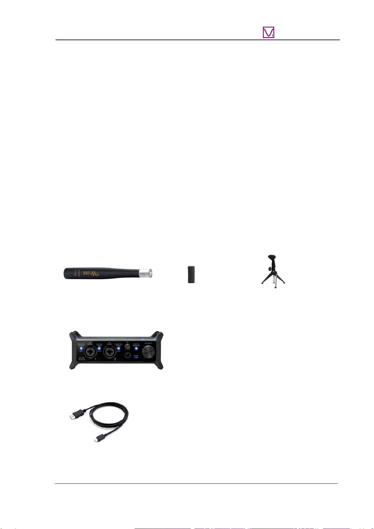
1.1 PACKAGE CONTENTS....................................................................................................................................3
1.1.1 Standard Package ................................................................................................................................3
1.1.2 Optional Items......................................................................................................................................4
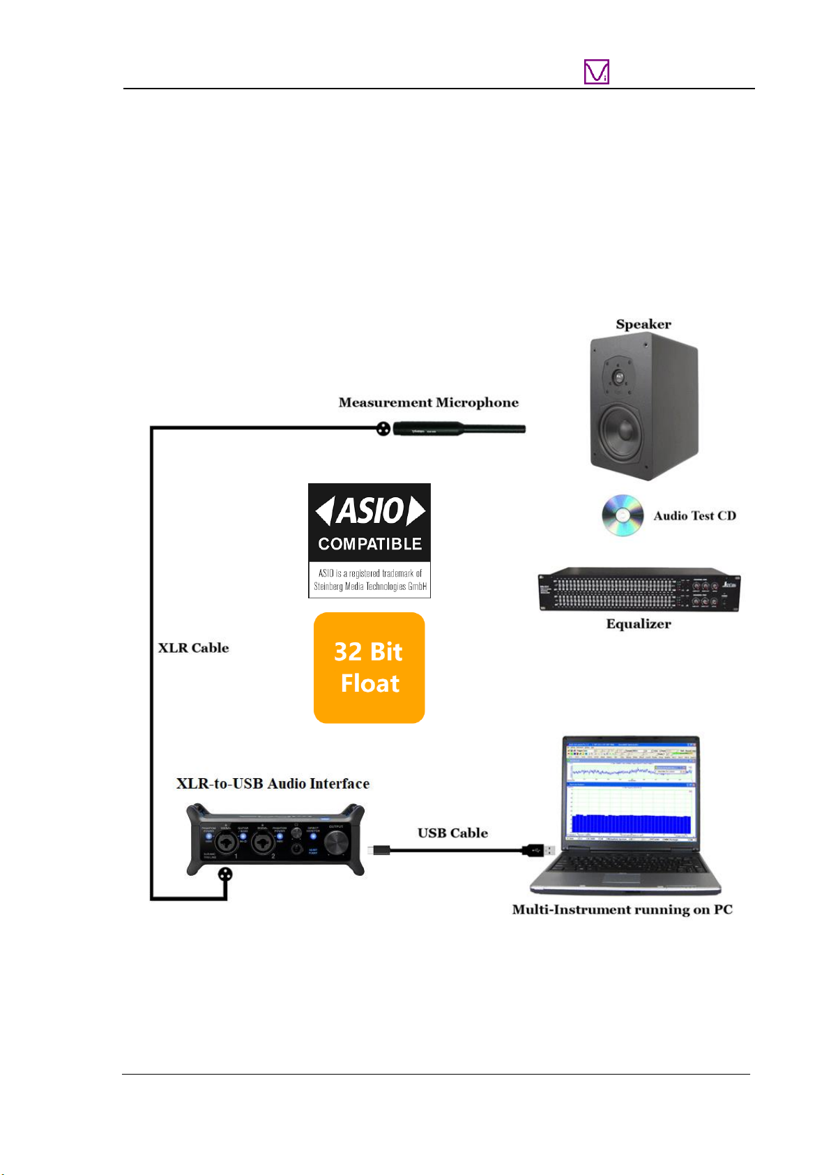
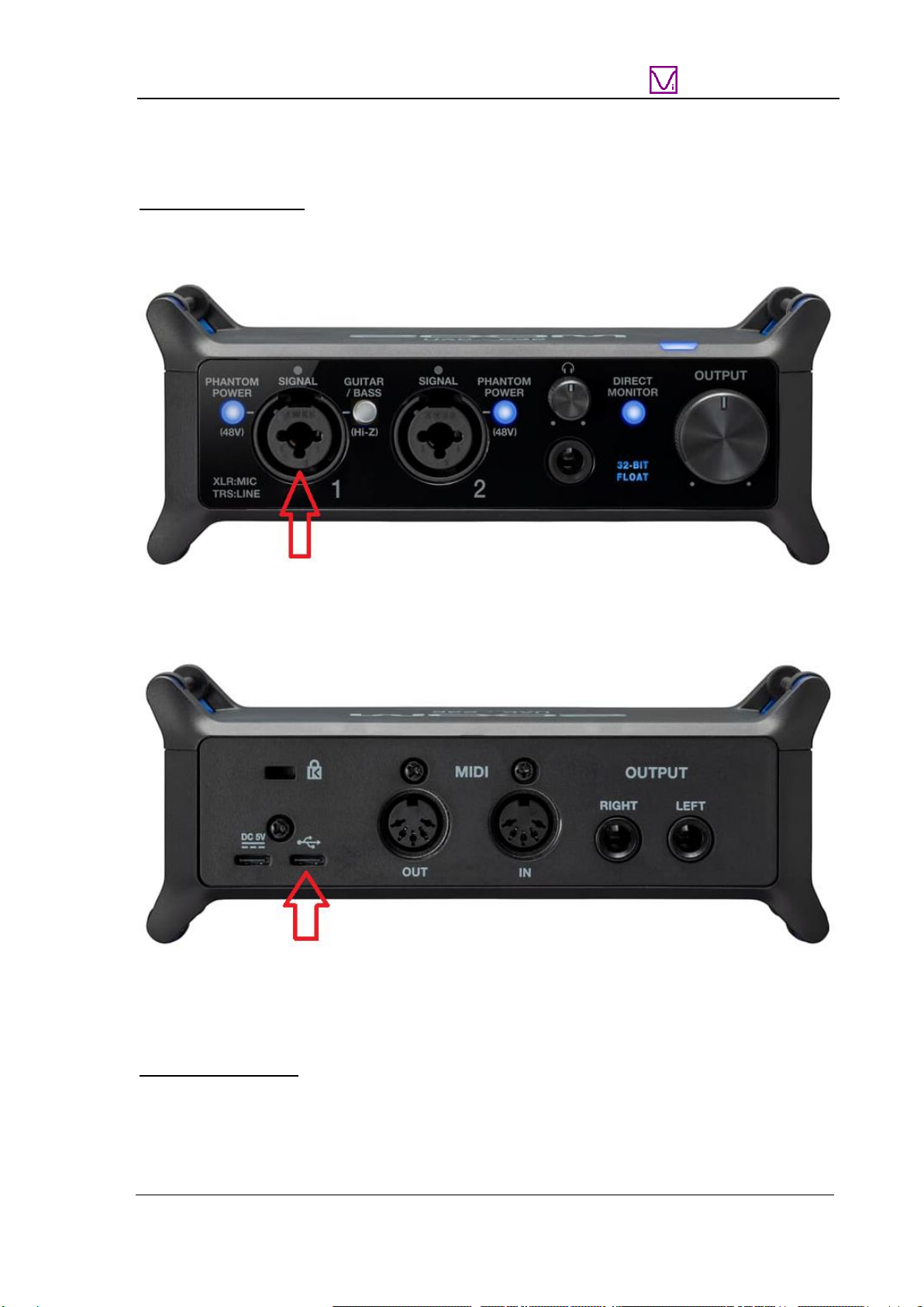
1.2 HARDWARE CONNECTION ............................................................................................................................5
1.3 HARDWARE DRIVER INSTALLATION.............................................................................................................6
1.4 MULTI-INSTRUMENT SOFTWARE INSTALLATION AND CONFIGURATION.......................................................6
1.4.1 Install Multi-Instrument.......................................................................................................................6
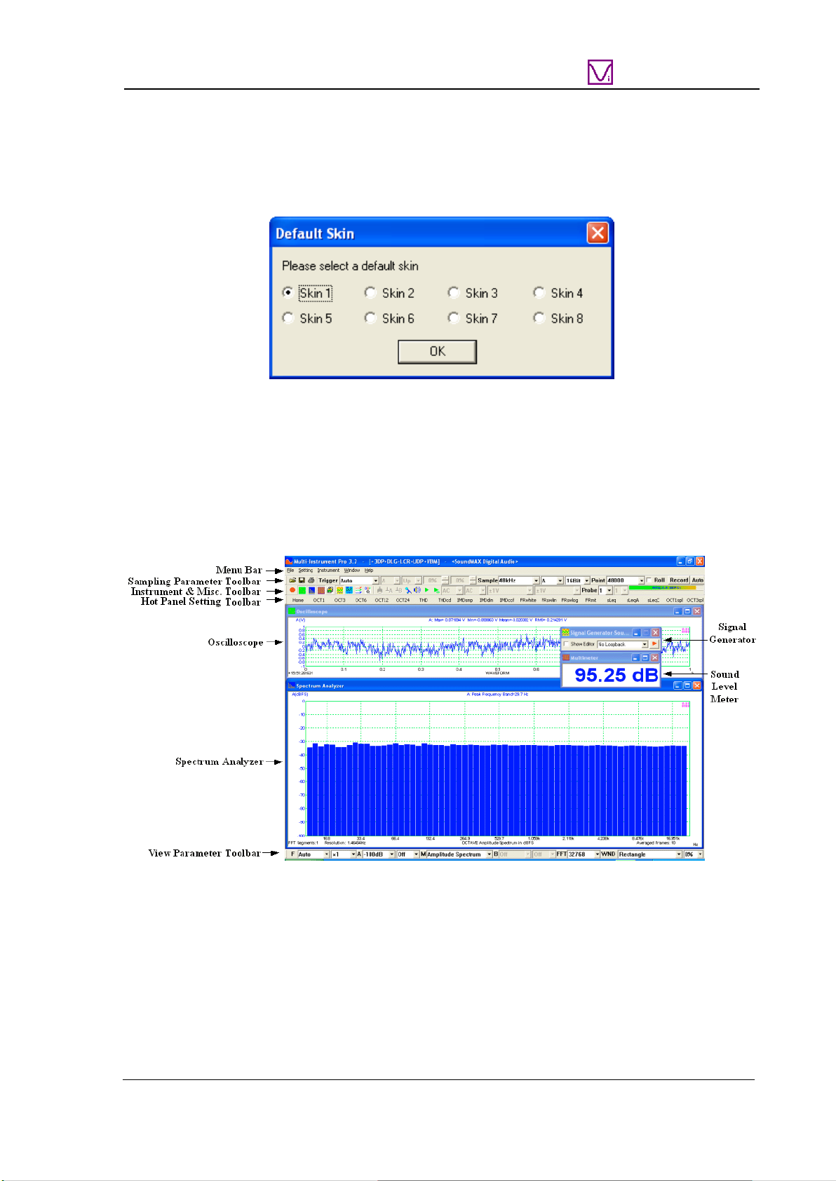
1.4.2 Start Multi-Instrument..........................................................................................................................6
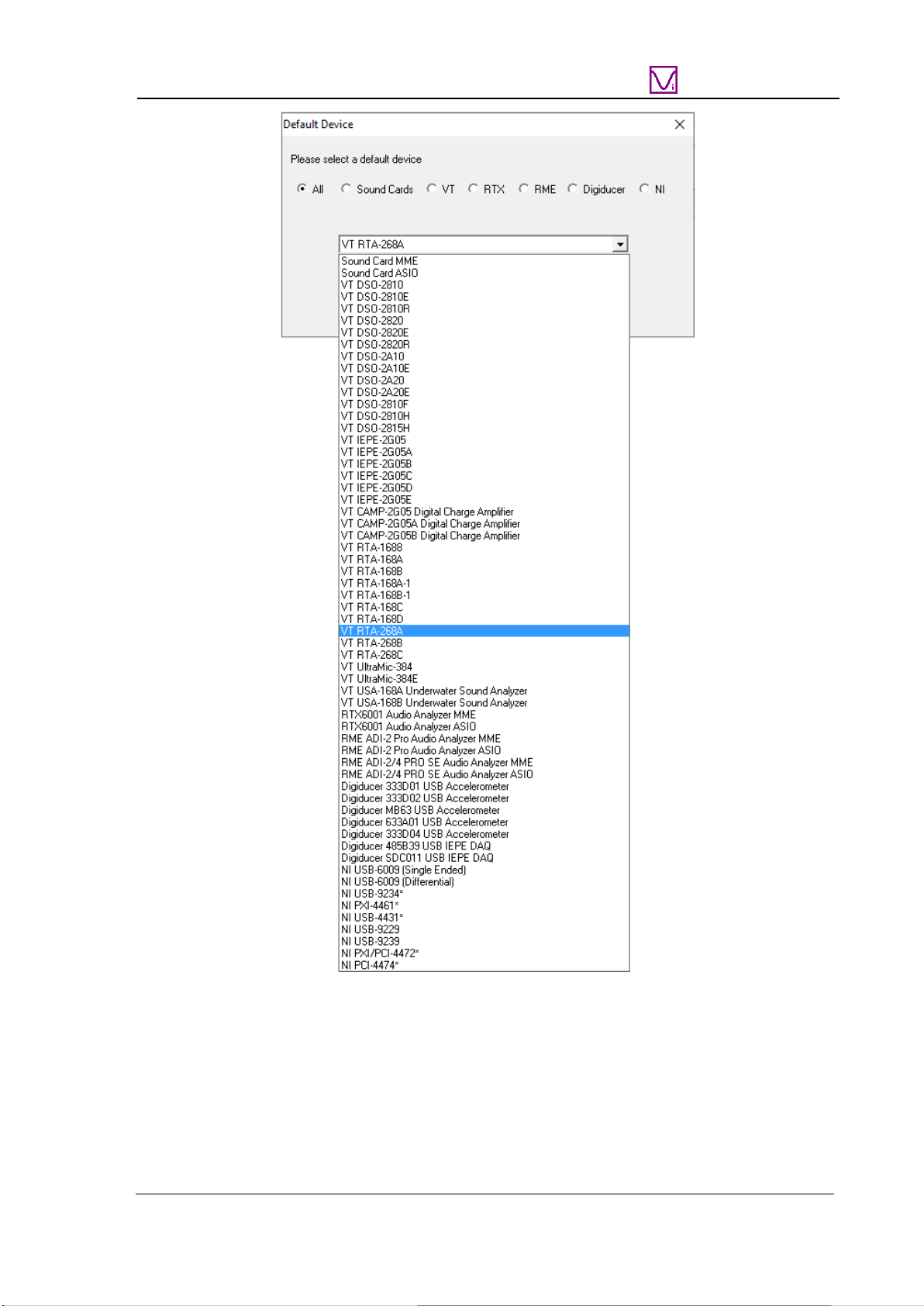
1.4.3 Configure Multi-Instrument .................................................................................................................8
1.5 INPUT OF SOUND LEVEL CALIBRATION DATA ............................................................................................13
1.5.1 0dB Reference Vr...............................................................................................................................14
1.6 MICROPHONE FREQUENCY COMPENSATION ...............................................................................................15
1.7TWENTY MOST FREQUENTLY USED MEASUREMENT SETTINGS .................................................................17
1.8 MORE ACOUSTIC ANALYSIS FUNCTIONS AVAILABLE IN MULTI-INSTRUMENT PRO OR ABOVE..................21
1.9 LIST OF AUDIO TEST WAV FILES (AUDIOTESTCD.ZIP) .............................................................................21
1.10 OPERATION NOTES ...................................................................................................................................23
1.11 UAC-232 CONTROL PANEL......................................................................................................................23
1.12 UAC-232 MIX CONTROL..........................................................................................................................24
1.13 TIME DELAY MEASUREMENT ...................................................................................................................25
1.13.1 Two-channel Time Delay Measurement using Cross Correlation ...................................................25
1.13.2 Single-channel Time Delay Measurement using Auto Correlation..................................................26
1.13.3 Single-Channel Time Delay Measurement using Pulse Emission....................................................27
1.14 AUDIO AND ULTRASOUND ANALYSIS.......................................................................................................27
2 SPECIFICATIONS.........................................................................................................................................28
2.1 VT RTA-268A/B/C HARDWARE CONFIGURATION.....................................................................................28
2.2 OVERALL VT RTA-268A/B/C SPECIFICATIONS.........................................................................................28
2.3 UAC-232 AUDIO INTERFACE SPECIFICATIONS...........................................................................................28
2.4 MEASUREMENT MICROPHONE M215 SPECIFICATIONS (FOR VT RTA-268A).............................................30
2.5 MEASUREMENT MICROPHONE M215L SPECIFICATIONS (FOR VT RTA-268B) ..........................................31
2.6 MEASUREMENT MICROPHONE M50 SPECIFICATIONS (FOR VT RTA-268C)...............................................32
2.7 MULTI-INSTRUMENT SOFTWARE SPECIFICATIONS......................................................................................33
3 MULTI-INSTRUMENT SOFTWARE LICENSE INFORMATION ........................................................42
3.1 LICENSE TYPES...........................................................................................................................................42
3.2 LICENSE UPGRADE FROM ONE LEVEL TO ANOTHER...................................................................................42
3.3 SOFTWARE UPGRADE IN THE SAME LICENSE LEVEL...................................................................................42
4 WARRANTY...................................................................................................................................................42
5 DISCLAIMER.................................................................................................................................................43

VT RTA-268A/B/C Manual Rev. 1.5
www.virtins.com 3 Copyright © 2010-2023 Virtins Technology
Virtins Technology
1 Installation and Quick Start Guide
VT RTA-268A/B/C is a series of PC-based ultra-low-noise real-time acoustic analyzers,
powered by the comprehensive virtual instrument software, Multi-Instrument®. The USB
audio interface used in the analyzers has two ADCs working in tandem to create a single
output data stream in 32-bit float format. One “low gain” ADC is optimized for high-level
signals, and the other “high gain” ADC is optimized for low-level signals. This state of the
art dual-ADC architecture provides an unmatchable dynamic range compared with the
conventional single ADC approach. With a proper microphone, it is now possible to capture
sound across the entire human hearing range without sacrificing fidelity at low signal levels
or encountering clipping at high signal levels, and this can be achieved without the hassle of
manual analog gain adjustment.
1.1 Package Contents
1.1.1 Standard Package
A standard VT RTA-268A/B/C Package contains the following items:
1) XLR Measurement microphone and its accessories (a windshield, a microphone clip and
stand)
2) XLR-to-USB Audio Interface
3) USB Cable (1 m)
4) XLR Cable (1.5 m)
XLR Measurement Microphone
Windshield
Microphone Clip and Stand

VT RTA-268A/B/C Manual Rev. 1.5
www.virtins.com 4 Copyright © 2010-2023 Virtins Technology
Virtins Technology
5) CD (containing the copy-protected Multi-Instrument software)
The latest software can always be downloaded from www.virtins.com/MIsetup.exe.
6) USB hardkey (containing a Multi-Instrument Pro license)
7) Audio Test WAV files (containing a list of audio test tones and noises)
They can be downloaded at: www.virtins.com/AudioTestCD.zip and then burnt into a CD
or saved into a USB memory stick. They can also be generated directly from the Signal
Generator of Multi-Instrument.
8) Carrying Case
9) Unique Sound Level Calibration Data (in CD)
10)Unique Microphone Calibration Data (in CD, only applicable to RTA-268C)
1.1.2 Optional Items
1) An additional XLR measurement microphone and its accessories
2) P48-to-IEPE converter (so that IEPE sensors can be connected to the XLR input)
3) IEPE sensors
4) Software license upgrade

VT RTA-268A/B/C Manual Rev. 1.5
www.virtins.com 5 Copyright © 2010-2023 Virtins Technology
Virtins Technology
1.2 Hardware Connection
Sound Measurement
Connect the XLR measurement microphone to the input jack 1 of the audio interface.
Connect the corresponding ends of the USB cable to the XLR-to-USB Audio interface and a
PC’s USB port. When this is complete, the blue LED at the top right corner of the front panel
lights up, indicating that it is receiving power.
Then switch on the 48V phantom power of input jack 1. This is required by the condenser
measurement microphone used here, meanwhile, the Guitar/Bass switch for HiZ support
MUST be turned off.
Software Activation
The USB hardkey needs to be plugged into any USB port of the PC in order to activate the
Multi-Instrument software. Otherwise the software will run under the 21-day fully functional
free trial mode before the trial period expires.

VT RTA-268A/B/C Manual Rev. 1.5
www.virtins.com 6 Copyright © 2010-2023 Virtins Technology
Virtins Technology
Test Signal Generation
You can generate the test signals from the Signal Generator of Multi-Instrument. The XLR-
to-USB audio interface has two ¼-inch TRS jacks on its back panel, respectively for left and
right balanced line-level outputs, and a ¼-inch TRS stereo headphone jack on its front panel.
The test signals output from these jacks can be fed into the audio system under test.
Alternatively, you can play the test signals from an audio CD or a memory stick.
1.3 Hardware Driver Installation
The device driver installer RTA268ABC_DriverInstaller.exe is located in the
Drivers\VTRTA268ABC directory in the CD. When you install the Multi-Instrument
software, a copy of the device driver installer will also be installed in the software installation
directory\Drivers\VTRTA268ABC. Run it to install the driver. After driver installation, the
device will be supported by both Sound Card MME and ASIO drivers in Multi-Instrument.
1.4 Multi-Instrument Software Installation and Configuration
Multi-Instrument is a powerful multi-function virtual instrument software. It supports a
variety of hardware ranging from sound cards which are available in almost all computers to
proprietary ADC and DAC hardware such as NI DAQmx cards, VT DSOs and so on. It
consists of multiple test instruments such Oscilloscope, Spectrum Analyzer, and Multimeter,
etc.
1.4.1 Install Multi-Instrument
Insert the Multi-Instrument installation CD into your computer’s CD-ROM drive and follow
the instruction on the screen to install the Multi-Instrument software. The installation file
can also be downloaded from www.virtins.com/MIsetup.exe.
1.4.2 Start Multi-Instrument
To start Multi-Instrument, on the Windows desktop, select [Start]>[All Programs]>[Multi-
Instrument]>[VIRTINS Multi-Instrument], or simply double click the MI icon.
If the software is started for the very first time after installation, it will prompt the user to
select a default device (see figure below). Select VT RTA-268A/B/C according to the
hardware device to be used.

VT RTA-268A/B/C Manual Rev. 1.5
www.virtins.com 7 Copyright © 2010-2023 Virtins Technology
Virtins Technology
The default device can also be changed later via [Setting]>[ADC Device], [Setting]>[DAC
Device], and [Setting]>[Configure Hot Panel Setting Toolbar], or simply [Setting]>[Restore
to Factory Default]. However, if [Restore to Factory Default] command is executed, all
calibration data entered manually via [Setting]>[Calibration] after software installation
will be reset to the default values of the selected product. To avoid the loss of the
manually entered calibration data, you can save them as a calibration file first.
Otherwise, you will have to enter the unique calibration data that come with the
product package again.

VT RTA-268A/B/C Manual Rev. 1.5
www.virtins.com 8 Copyright © 2010-2023 Virtins Technology
Virtins Technology
In case the driver has not yet been installed, the software will prompt the user to install the
driver. Restarting program is required after that.
After the default device is selected, the software will prompt the user to select a default color
scheme (Skin). The default skin can also be changed later via [Setting]>[Display].
The main window of the software will open after the above skin selection. The following
figure shows a typical screen layout (obtained by clicking the “OCT3” button in the Hot
Panel Setting Toolbar after the launch of the software). Please refer to the software manual
for detailed functions of the software. The software manual can be accessed via [Start]>[All
Programs]>[Multi-Instrument]>[VIRTINS Multi-Instrument Manual] (in PDF format) or
[VIRTINS Multi-Instrument Help] (in HTML format) on Windows Start menu, or
[Help]>[Software Manual] or F1 inside the software.
1.4.3 Configure Multi-Instrument
In Multi-Instrument, the menu items are enabled / disabled based on context. Many menu
items are disabled when the Oscilloscope or the Signal Generator is running. To do the
configuration, stop the oscilloscope first by pressing the green button at the upper left corner
of the screen (see figure below). The button will turn red once the Oscilloscope is stopped.

VT RTA-268A/B/C Manual Rev. 1.5
www.virtins.com 9 Copyright © 2010-2023 Virtins Technology
Virtins Technology
1.4.3.1 Configure Sound Recording Devices for Multi-Instrument
The audio interface can be used with either MME or ASIO driver. ASIO driver is
recommended as it uses the sampling rate selected in Multi-Instrument directly and bypasses
the possible sampling rate conversion and audio signal enhancement by Windows, which
may otherwise alter the original samples and lead to measurement inaccuracies.
1.4.3.1.1 Using ASIO Driver
Go to [Setting]>[ADC Device], and select “Sound Card ASIO”in the “Device Model”field.
Then choose “ZOOM UAC-232 ASIO Driver” in the “Device No.” field (see figure below).
This is to configure the audio interface as the sound recording device for the software.
Click the “Control Panel”button to bring up the control panel for the audio interface (see
figure below).
1.4.3.1.1.1 Buffer Size

VT RTA-268A/B/C Manual Rev. 1.5
www.virtins.com 10 Copyright © 2010-2023 Virtins Technology
Virtins Technology
There is generally no need to change the default Buffer Size for test and measurement
applications. A large buffer size is preferred, though.
1.4.3.1.1.2 Sampling Rate
Under ASIO, the Sampling Rate will be set directly in Multi-Instrument and thus changing it
here will have no effect. Instead, the Sampling Rate here will passively follow what is set in
Multi-Instrument.
On the other hand, if MME is used instead, you can only change the actual sampling rate of
the audio interface here. The change here will be reflected in the sampling rate displayed in
the Sound Recording Tab under the Windows Control Panel. When the sampling rate set in
Multi-Instrument differs from the one here, Windows will conduct sampling rate conversion
automatically.
1.4.3.1.1.3 Format
Two formats are supported by the audio interface: 24-bit (Integer) or 32-bit Float. One
unique feature of the audio interface is its support for 32-bit float format. This format
provides much finer resolution than the 24-bit (Integer) format when the signal is weak,
thanks to the audio interface’s state of the art dual-ADC architecture, with one optimized for
weak signals and the other optimized for strong ones. Both formats have the same resolution
when the signal is strong. It is thus recommended to use the 32-bit float format for sound
recording (ADC). However, currently its ASIO driver does not support 32-bit float format
for signal output (DAC). Hence, MME should be used for sound playback (DAC) instead.
When the 32-bit float format is used, the Sampling Bit Resolution in Multi-Instrument must
be set to 32-bit, otherwise, an error message will pop up. When the ADC is running in the
32-bit float mode, the “32-Bit FLOAT”sign on the front panel of the audio interface will be
lit up, and “Float32”will be displayed at the middle bottom of the Oscilloscope window in
Multi-Instrument.
Now, if you start the oscilloscope by pressing the red button at the upper left corner of the
screen, and then talk before the measurement microphone, you should be able to see your
“voices” in the Oscilloscope and Spectrum Analyzer.
1.4.3.1.2 Using MME Driver
Go to [Setting]>[ADC Device], and select “Sound Card MME”in the “Device Model”field.
Then choose “Line (ZOOM UAC-232 Audio)” in the “Device No.” field (see figure below).
This is to configure the audio interface as the sound recording device for the software.

VT RTA-268A/B/C Manual Rev. 1.5
www.virtins.com 11 Copyright © 2010-2023 Virtins Technology
Virtins Technology
Note that the displayed name of the audio interface may vary a bit under different Windows
versions or with different USB ports.
Now, if you start the oscilloscope by pressing the red button at the upper left corner of the
screen, and then talk before the measurement microphone, you should be able to see your
“voices” in the Oscilloscope and Spectrum Analyzer.
Note that MME does not support 32-bit float format.
1.4.3.2 Configure Sound Playback Devices for Multi-Instrument
The audio interface has left and right balanced line-level outputs and a stereo headphone
output. You can use the Signal Generator in Multi-Instrument to generate the test signals
through them.
If ASIO with 32-bit float format (recommended) is used for sound recording (ADC), MME
must be chosen for sound playback (DAC). To do that, go to [Setting]>[DAC Device], and
select “Sound Card MME”in the “Device Model”field and “Line (ZOOM UAC-232
Audio)”in the “Device No.” field (see figure below).

VT RTA-268A/B/C Manual Rev. 1.5
www.virtins.com 12 Copyright © 2010-2023 Virtins Technology
Virtins Technology
If ASIO with 24-bit format is used for sound recording (ADC), ASIO must be chosen for
sound playback (DAC). To do that, go to [Setting]>[DAC Device], and select “Sound Card
ASIO”in the “Device Model”field and “ZOOM UAC-232 ASIO Driver”in the “Device
No.” field (see figure below).
If MME is used for sound recording (ADC), then MME must be chosen for sound playback
(DAC).
Now, if you press the Signal Generator button (see figure above), the Signal Generator panel
will be opened (see figure below). Press the red triangle button at the upper right corner of
the Signal Generator panel, you should hear a 1kHz test tone from the speaker or earphone
connected to the audio interface. Press it again to stop the sound.

VT RTA-268A/B/C Manual Rev. 1.5
www.virtins.com 13 Copyright © 2010-2023 Virtins Technology
Virtins Technology
1.5 Input of Sound Level Calibration Data
Sound Level Calibration is not required for those relative measurements such as frequency
response, THD, THD+N, IMD, etc.. It is required only if you want to measure the absolute
sound level.
Please refer to the calibration data sheet provided in the product package and enter the
calibration data in the respective highlighted fields in the Calibration Setting dialog box (see
figures below). The Calibration Setting dialog box can be opened via [Setting]>[Calibration]
in Multi-Instrument. Note that the “0dB Reference Vr”calibration data in the following
figure are examples only. You should enter the actual calibration data provided inside the
product package.

VT RTA-268A/B/C Manual Rev. 1.5
www.virtins.com 14 Copyright © 2010-2023 Virtins Technology
Virtins Technology
The audio interface has an ultra-low noise level and offers a huge dynamic range of about
135dB, owing to its state of the art dual-ADC architecture. Consequently, the absence of
analog gain adjustment knobs on the audio interface panel is a deliberate design choice, as
the exceptional dynamic range eliminates the need for such adjustments.
The audio interface also comes with a piece of utility software called UAC-232 Mix Control
(see Section 1.12), where the digital gain of the input channels 1 & 2 can be adjusted from
0dB to 60dB. Please note that the calibration data are valid only when the digital gains
are set at 0dB. The digital gain should always be kept at 0dB in order not to invalidate the
calibration. Under the 32-bit float mode, the quality of the acquired data will not be affected
by the digital gain settings.
1.5.1 0dB Reference Vr
The “0dB Reference Vr”in the Calibration Setting dialog box is used to finally calibrate the
input voltage to dBSPL. The input voltage here should be considered as a relative value as
the actual input is not a voltage but a sound pressure. The “0dB Reference Vr”is the
parameter to be recalibrated if a sound level recalibration is necessary. To do the
recalibration, simply enter the actual sound level value into the “Actual Value”edit box and
the measured sound level value into the “Read Value”edit box, and then press the
“Calculate”button ONCE. It should be noted that the Sensor Sensitivity is kept at 1V/V in
this method.
In case you want to display the measured raw data in Pa rather than Volt, then you should
enter the “actual”Sensor Sensitivity in V/Pa, which can be calculated using the following
formula:

VT RTA-268A/B/C Manual Rev. 1.5
www.virtins.com 15 Copyright © 2010-2023 Virtins Technology
Virtins Technology
Sensitivity = [“0dB Reference Vr”(in Volt)] / [Standard 0dB Reference (in Pa)]
where the Standard 0dB Reference for sound pressure level in air is 20 µPa (i.e. 2e-005 Pa)
and that in water is 1 µPa (i.e. 1e-006 Pa). If the “actual”Sensor Sensitivity is used, then the
standard 0dB reference should be entered into the “0dB Reference Vr”edit box. For
example, the following two methods are equivalent.
Method 1: [0dB Reference Vr] = 8e-007 (V) and [Sensor Sensitivity] = 1 V/V
Method 2: [0dB Reference Vr] = 2.0e-005 (Pa) and [Sensor Sensitivity] = 0.04 V/Pa
1.6 Microphone Frequency Compensation
The measurement microphones in RTA-268 series have extremely flat frequency responses
in the audio frequency range. Generally, there is no need to compensate for the microphone
frequency response. However, a higher degree of accuracy can be achieved if the
microphone comes with a frequency response file or a frequency compensation file. The
difference between these two files is the sign of the gain values (in dB). For example, a gain
of 3dB in a frequency response file should have a gain of -3dB in its equivalent frequency
compensation file.
The XLR measurement microphone in RTA-268C comes with an individually calibrated
Original Frequency Response File RTA-268C.txt. “Original” means that it has exactly the
same format and contents as the calibration file provided by the microphone manufacturer.
This file is located in the CD directory “\Microphone Frequency Compensation File”.
Please copy this file to the “\fcf”directory under the installation directory of Multi-
instrument in the hard disk (if the file already exists, overwrite it), so that you can use it
later. This file is also used by the default panel settings configured in the Hot Panel Setting
Toolbar (The third toolbar from the top), except the buttons labelled “Ultrasound”, “TDac”,
“TDcc” and “TDgcc”.
You can load the Original Frequency Response File by right clicking anywhere within the
Spectrum Analyzer window, selecting [Spectrum Analyzer Processing]> “Intra-Frame
Processing”> “Compensation 1”, changing the “Files of type”from “Frequency
Compensation File (*.fcf)”to “Original Frequency Response File (*.txt)”in the pop-up File
Open dialog box, and loading that file (see figures below). If you want to apply it to the
twenty most frequently used panel settings in the Hot Panel Setting Toolbar, you will need to
configure and save the corresponding panel setting files one by one. Luckily, this has already
been done for the default panel settings.

VT RTA-268A/B/C Manual Rev. 1.5
www.virtins.com 16 Copyright © 2010-2023 Virtins Technology
Virtins Technology
Some Windows versions / editions come with some audio signal enhancement features which
are enabled by default. These features must be disabled through the Sound Recording Control
under Windows Control Panel to prevent them from altering the originally sampled data, as

VT RTA-268A/B/C Manual Rev. 1.5
www.virtins.com 17 Copyright © 2010-2023 Virtins Technology
Virtins Technology
shown below. One of the possible problems caused by these features is the unwanted
alteration of the frequency response of the setup. Using ASIO driver instead of MME driver
can avoid these problems.
1.7 Twenty Most Frequently Used Measurement Settings
Multi-Instrument bundled with VT RTA-268A/B/C comes with many pre-configured panel
setting files. This saves you time in configuring various parameters for some frequently
performed measurements by yourself. You can load these panel setting files via
[Setting]>[Load Panel Setting]. Furthermore, 20 most frequently used panel setting files are
pre-configured in the Hot Panel Setting Toolbar (The third toolbar from the top). You can
load one of them by a single mouse click. These 20 measurement settings are:
(1) Home: Default Setting
The factory default panel setting. It is equivalent to the [File]>[New] command.
(2) OCT3spl: 1/3 Octave Analysis (Avg. 10) in SPL
Pink noise will be generated by pressing the start button of the Signal Generator. The pink
noise will be injected into the DUT (Device Under Test), and the response of the DUT will
be captured and analyzed by the Oscilloscope and Spectrum Analyzer. A flat curve in the
Spectrum Analyzer would indicate a flat magnitude frequency response of the DUT. The
equivalent continuous sound level in dB will be displayed in the Multimeter window.

VT RTA-268A/B/C Manual Rev. 1.5
www.virtins.com 18 Copyright © 2010-2023 Virtins Technology
Virtins Technology
(3) OCT3ppn: 1/3 Octave Analysis
Same as OCT3spl, but periodic pink noise instead of ordinary (non-periodic) pink noise is
used as the stimulus. One advantage of using periodic pink noise is that its spectrum is
ideally flat under octave analysis even without inter-frame averaging. Also, the Y axis is
displayed in dBFS instead of dBSPL in Spectrum Analyzer.
(4) Polarity: Speaker, Microphone, Amplifier Polarity Tester with Crest Factor Check
A polarity test signal will be generated by pressing the start button of the Signal Generator.
Point the microphone close to the center of the speaker under test along its axis, and observe
the polarity of the captured pulse in the oscilloscope window. If the pulse goes positive
initially, then the polarity of the speaker under test is positive, and vice versa.
Positive Negative
(5)
RT60pn: Reverberation Analysis via Interrupted Noise (1/1 Octave Band) (applicable to VT
RTA-268A/B)
Pink noise will be generated for 5 seconds only by pressing the start button of the Signal
Generator. It will be projected into the enclosure under test. After about 4.5 seconds, the
Oscilloscope will be started automatically by the software under the “Sync. No Loopback”
mode of the Signal Generator. This is to capture the last 0.5 second of the emitted pink noise
and 4.5 seconds of its subsequent decay process. The data analysis may take quite a long
time. Please be patient! The measured RT20 value in each 1/1 octave band as well as its
overall value will be displayed. RT30 can also be displayed if needed. Please refer to the
sections for Reverberation in the software manual for details.
Ultrasound: Audio and Ultrasound Analysis (applicable to VT RTA-268C)
Unlike other pre-configured panel settings in this toolbar, the microphone frequency response
file RTA-268C.txt is not configured in the Spectrum Analyzer in order to allow for a much
wider frequency range, which is theoretically from 0 to 96 kHz.
(6) RT60imp: Reverberation & Speech Intelligibility Analysis via Impulse Response (1/1
Octave Band)
Reverberation and Speech intelligibility analysis will be performed based on Impulse
Response Schroeder Integration. The impulse response can be obtained through direct
methods (such as a gunshot) or indirect methods (such as transfer function measurement).
The data analysis may take quite a long time. Please be patient! Please refer to the
sections for Reverberation and Speech Intelligibility in the software manual for details.
(7) THDcd: THD,THD+N,SNR,SINAD,Noise Level, ENOB (Avg. 10 )
A 1 kHz sine wave will be generated by pressing the start button of the Signal Generator. The
sine wave will be injected into the DUT (Device Under Test), and the response of the DUT

VT RTA-268A/B/C Manual Rev. 1.5
www.virtins.com 19 Copyright © 2010-2023 Virtins Technology
Virtins Technology
will be captured and analyzed by the Oscilloscope and Spectrum Analyzer. All the above
parameters of the DUT will be measured and displayed. This panel setting should be used if
different sound cards are used for signal input and output. It should also be used if the 1 kHz
test tone is played from an audio CD or a memory stick.
(8) IMDsmp: IMD SMPTE (60 Hz + 7 kHz, 4:1) (Avg. 10)
A 60 Hz and a 7 kHz sine waves mixed at an amplitude ratio of 4:1 will be generated by
pressing the start button of the Signal Generator. The mixed signals will be injected into the
DUT (Device Under Test), and the response of the DUT will be captured and analyzed by the
Oscilloscope and Spectrum Analyzer. The SMPTE IMD value of the DUT will be measured
and displayed.
(9) IMDdin: IMD DIN (250 Hz + 8 kHz, 4:1) (Avg. 10)
A 250 Hz and an 8 kHz sine waves mixed at an amplitude ratio of 4:1 will be generated by
pressing the start button of the Signal Generator. The mixed signal will be injected into the
DUT (Device Under Test), and the response of the DUT will be captured and analyzed by the
Oscilloscope and Spectrum Analyzer. The DIN IMD value of the DUT will be measured and
displayed.
(10) IMDccif: IMD CCIF2 (19 kHz + 20 kHz, 1:1) (Avg. 10)
A 19 kHz and a 20 kHz sine waves mixed at an amplitude ratio of 1:1 will be generated by
pressing the start button of the Signal Generator. The mixed signal will be injected into the
DUT (Device Under Test), and the response of the DUT will be captured and analyzed by the
Oscilloscope and Spectrum Analyzer. The CCIF2 IMD value of the DUT will be measured
and displayed.
(11) FRwhite: Magnitude Frequency Response (White Noise, Avg. 30)
White noise will be generated by pressing the start button of the Signal Generator. The white
noise will be injected into the DUT (Device Under Test), and the response of the DUT will
be captured and analyzed by the Oscilloscope and Spectrum Analyzer. The curve in the
Spectrum Analyzer indicates the magnitude frequency response of the DUT.
(12) FRpwn: Magnitude Frequency Response (Periodic White Noise)
Periodic white noise will be generated by pressing the start button of the Signal Generator.
The periodic white noise will be injected into the DUT (Device Under Test), and the
response of the DUT will be captured and analyzed by the Oscilloscope and Spectrum
Analyzer. The curve in the Spectrum Analyzer indicates the magnitude frequency response
of the DUT. One advantage of using periodic white noise is that its spectrum is ideally flat
even without inter-frame averaging.
(13) FRswLin: Magnitude Frequency Response (Frequency Sweep, Linear)
A 0.68266667-second 20Hz-to-20kHz linear frequency swept sine wave will be generated by
pressing the start button of the Signal Generator. The signal will be injected into the DUT
(Device Under Test), and the response of the DUT will be captured by the Oscilloscope and
Spectrum Analyzer. The curve in the Spectrum Analyzer indicates the magnitude frequency
response of the DUT. Note that you will need to adjust the trigger level so that the
Oscilloscope will be triggered just upon the start of the sweep.
(14) FRswLog: Magnitude Frequency Response (Frequency Sweep, Log)

VT RTA-268A/B/C Manual Rev. 1.5
www.virtins.com 20 Copyright © 2010-2023 Virtins Technology
Virtins Technology
A 0.68266667-second 20Hz-to-20kHz logarithmic frequency swept sine wave will be
generated by pressing the start button of the Signal Generator. The signal will be injected into
the DUT (Device Under Test), and the response of the DUT will be captured by the
Oscilloscope and Spectrum Analyzer. The curve in the Spectrum Analyzer indicates the
magnitude frequency response of the DUT. Note that you will need to adjust the trigger level
so that the Oscilloscope will be triggered just upon the start of the sweep.
(15) FRmt: Magnitude Frequency Response (MultiTone, 31 1/3 Octave Bands)
A multitone consists of 31 1/3 octave band center frequencies from 20 Hz to 20kHz will be
generated by pressing the start button of the Signal Generator. The signal will be injected into
the DUT (Device Under Test), and the response of the DUT will be captured by the
Oscilloscope and Spectrum Analyzer. The curve in the Spectrum Analyzer indicates the
magnitude frequency response of the DUT.
(16)sLeq: Short Equivalent Continuous Sound Level (Short Leq, 125ms)
This panel setting will display the short equivalent continuous sound level. The value is time-
averaged over continuous 125 ms.
(17)sLeqA: Short Equivalent Continuous Sound Level (Short Leq, 125ms) (A-Weighted)
This panel setting will display the A-weighted short equivalent continuous sound level. The
value is time-averaged over continuous 125 ms.
(18)TDac: Single-Channel Time Delay Measurement via Auto Correlation
White noise will be generated from Output Ch.A by pressing the start button of the Signal
Generator. The superimposed direct and reflected signals from Input Ch.A will be captured
and analyzed by the Oscilloscope and Spectrum Analyzer. The time delay between them will
be measured by locating the second highest auto correlation peak along the time axis. The
corresponding auto correlation coefficient will also be displayed. A positive coefficient
indicates that the superimposed two signals are positively correlated and vice versa. A
deadband of 0.25ms is configured in [Spectrum Analyzer Processing] by default to enforce a
minimum interval between the first and second highest auto correlation peaks in order to
avoid false peak identification.
(19)TDcc: Dual-Channel Time Delay Measurement via Cross Correction (oB->iB)
White noise will be generated from Output Ch.B by pressing the start button of the Signal
Generator. The signals from Input Ch.A and Ch.B will be captured and analyzed by the
Oscilloscope and Spectrum Analyzer. The time delay between them will be measured by
locating the highest cross correlation peak along the time axis. The corresponding cross
correlation coefficient will also be displayed. A positive coefficient indicates the two signals
are positively correlated and vice versa. The signal fed to Input Ch.B can also be a loopback
signal from Output Ch.B. If that is the case, it is assumed that the loopback is done through
UAC-232 Mix Control without any external connection. The Output Ch.A is set to NONE to
cut off the loopback from Output Ch.A to Input Ch.A. The test signal will be output from
Output Ch.B only. This loopback method introduces a system lag that is a function of
sampling rate (e.g. 625μs@48kHz, 250μs@192kHz). It can be removed from the measured
time delay using UDDP (User Defined Data Point). This corrected time delay will also be
shown.
(20)TDgcc: Dual-Channel Time Delay Measurement via Generalized Cross Correction
(oB->iB)
This manual suits for next models
2
Table of contents
Other VIRTINS Measuring Instrument manuals
Popular Measuring Instrument manuals by other brands

UEi
UEi DL389B instruction manual

Zebra-Tech
Zebra-Tech MEASURING BOARD Operation manual

Hanna Instruments
Hanna Instruments HI99151 instruction manual

Endress+Hauser
Endress+Hauser Waterpilot FMX21 operating instructions

Sonel
Sonel CMP-1015-PV user manual

Endress+Hauser
Endress+Hauser Cerabar M operating instructions

Tektronix
Tektronix TDSUSB2 manual

palintest
palintest Lumiso Pooltest Expert quick start guide

BROWIN
BROWIN 405570 Nstructions for use

AquaLabo
AquaLabo CORAIL user guide

elsner elektronik
elsner elektronik KNX eTR M1 Technical specifications and installation instructions

Omega
Omega Volume VII-System Description Operation manual