GTD G53F User manual

Gemini G53F German Equatorial Mount User Manual Ver2.7
Contents
General.................................................................................................................................................1
Technical parameters.......................................................................................................................2
Delivered Parts.................................................................................................................................2
Mount specific Pulsar2 parameters..................................................................................................2
Assembling/Disassembling the two parts.............................................................................................2
Ad usting Polar Elevation and Azimuth...............................................................................................5
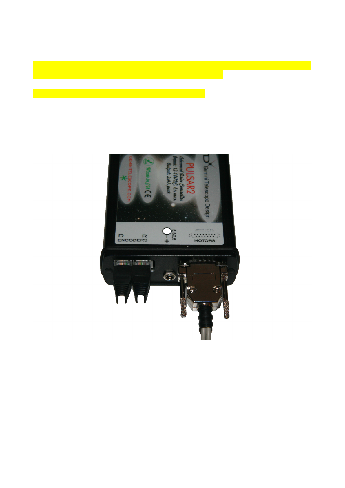
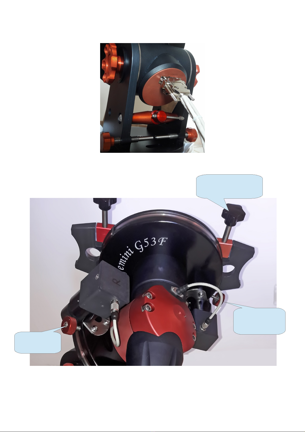
Connecting Cables................................................................................................................................6
Using the G53F.....................................................................................................................................9
First time setup.................................................................................................................................9
Making a goto................................................................................................................................10
Absolute Position Reference..........................................................................................................11
Using real time tracking speed correction.....................................................................................12
Practical hints.................................................................................................................................12
Astrophotography with the G53F..................................................................................................13
Remote use of the G53F.....................................................................................................................14
Maintenance.......................................................................................................................................14
General
The G53F is a Friction Drive Telescope Mount, there are no traditional gears used.
This ensures smooth, high precision and backlash free motion in silence. Moving
parts roll on each other which guarantees a long life.
The drive unit consists of a stepper motor, reduction gear Gemini Fluido) and the
drive roller. The drive roller is pushed against the drive disk with the torque limited
lock knob. The gearing has an integrated slip clutch that prevets demage to the
drive roller and the gearing itself.
To ensure high goto precison, encoders are fitted directly to both axes. The
encoders correct any slip that may occur if the slip clutch enters in action or the lock
knobs are opened. If you hear a beep after a goto that indicates a large slip that will
not be corrected for safety reasons – the mount probably has hit something.
Both encoders have an absolute position signal that helps recovering lost
positioning in remote applications. The RA encoder can be used to correct tracking
speed for unguided photography. All cables are routed internally as of 06.2016)
The equatorial head can be separated in two parts for transport and storage.
G53F manual ver 2.7 p1 June 2017 www.geminitelescope.com

Technical parameters
Steppers: NEMA 17, 400 step, 1,5 Amp
Drive disk: D 220 mm, stainless steel
Drive roller: D 6 mm, hardened and coated steel
Encoders: Optical incremental, 72 000 pulse/rev
Weight: 20 kg
Load capacity: 45 kg
Maximum unbalanced torque: 15 Nm 1,5kg at 1m radius)
Elevation range: 20 - 90 deg
Temperature range: -20 to +30
Driver: Pulsar2 http://www.geminitelescope.com/pulsar-goto-controllers/
Slewing precision: cca +/- 30 arcsec
Max slewing speed with Pulsar2. 4 deg/sec
Tracking precision: 2”/5 minutes
Power: 12-18VDC, 3A 1A continuous draw at 12V)
Telescope interface: Losmandy rail or custom
Delivered Parts
Equatorial head with Losmandy adapter, Counterweight shaft 30mm), Pulsar2 driver with
hand controller, cables, cable guide ring. Optional: counterweights, polar finder, tripod,
splitter box for the 12VDC supply on the RA head specify length, number and type of
connectors).
Mount specific Pulsar2 parameters
Non default values only)
Total Red: enter 350, the exact value will be calculated by Pulsar2
Track current: 850mA
GoTo current: 1200mA
Stop current: 400mA or 800 for guided photography
Motor step R/D: 400
Encoders: Mount encoders are fitted answer Yes to Mount encoder RA and DEC,
answer No to Motor encoder RA and DEC)
Resolution: 72 000 both RA and DEC
Rotation: leave as it is, will be defined by Pulsar2
Umod Sp limit user parameters) 990
Ramp user parameters) Ra 1, Dec 2
Backlash user parameters):0 arcsec
There are videos on YouTube to help with the setup and other features. Visit this link to see the
updated list: http://www.geminitelescope.com/gemini-german-fork-mounts-goto-manuals/
G53F manual ver 2.7 p2 June 2017 www.geminitelescope.com
Power supply choice: universal laptop psu, traditional linear transformer +rectifyer), car or solar panel lead
battery are all suitable. Switching PSUs can sometimes create interference and not work properly. IF
YOUR MOTOR DO NOT WORK PROPERLY TOP AND DO NOT CHANGE PARAMETER ! U E A
CAR BATTERY. IF THI DOE NOT OLVE THE PROBLEM CONTACT U FOR ADVICE!!

Assembling/Disassembling the two parts
1 To assemble the G53F Equatorial Head, rotate the RA head into the
approximate position shown below, lock the red lock knob until it emits a click,
and place the DEC head into the saddle as shown below. Attention, it may fall
out of the saddle if left alone in an unsuitably horizontal position!
Make sure the orienting pin in the lower saddle engages the hole in the DEC
head. This ensures the correct contact of the DB9 connector.
2 Next, place the upper saddle on the DEC head as shown below. Find the
position when the bolts enter their relative threaded holes in the lower saddle.
The gaps at the two sides should be approximately equal.
G53F manual ver 2.7 p3 June 2017 www.geminitelescope.com
Lock until you
hear a click

3 Fasten the 4 bolts evenly, changing sides frequently. Fasten them firmly
finally. You will need a 6 mm Allen key hexagonal).
You are ready now. Disassembling is the reverse of assembling.
G53F manual ver 2.7 p4 June 2017 www.geminitelescope.com
Gap on either side
should be approx. equal

Adjusting Polar Elevation and Azimuth
The adjustment range of the elevation screw is cca 20 degrees. If you need
more adjustment you have to reposition the RA head in the elevation plates
as explained below.
1 Remove the DEC head from the RA head. This makes the procedure much
more easy to do.
2 Turn the elevation screw close to the OUT position. when the threaded rod
has most of its length between the two cross rods) This makes the procedure
easier.
3 Remove both elevation locks and the centering rings which are below the
locks. These come out if you release all load on them by turning the mount
head on its side for example.
4 Pull out backwards the RA head from the fork base.
G53F manual ver 2.7 p5 June 2017 www.geminitelescope.com
1
4

5 The pin is marked with a blue dot. You must pull the plates away and put
the pins into the correct holes 1 to 4) for your desired latitude. The actual
position 2) is for mid Northern/Southern latitudes, 4 is down to 20 deg, 1 is
for far North.
6 Push the RA head back into the fork base, insert the centering rings and the
locks, finally mount the DEC head.
To fine adjust elevation and azimuth use the screws indicated below.
1 turn of the elevation screw is cca 0,6 degree change in elevation.
Connecting Cables
You need to connect 3 plugs to Pulsar2 and one to the G53F. The rest is
routed internally. You also have a power plug routed to the RA head to supply
all your 12V DC equipment on the scope, without additional cables.
G53F manual ver 2.7 p6 June 2017 www.geminitelescope.com
Azimuth control
Elevation control
turn ccw to elevate
Release ¼ turn on
Both sides before
Adjusting elevation

You can order an optional splitter box with the connectors you specify for your
equipment's power requirements.
Important notice: the RA axis is limited in its rotation at Hour Angle 12h with a
hard stop. Do not attemp to force it over this position.
The DEC axis can be rotated without restriction.
Pulsar2 side of cable connections shown below. The cable is cca 60 cm long.
No damage will occur if you swap the encoder cables but the mount will not
operate correctly. The plugs are marked R and D for identification.
G53F manual ver 2.7 p7 June 2017 www.geminitelescope.com

Mount side connector
G53F manual ver 2.7 p8 June 2017 www.geminitelescope.com
RA lock knob
DEC lock knob
Losmandy lock knobs

Using the G53F
First time setup
If you are using the G53F for the first time or have replaced the Pulsar2
controller check the Mount Parameters in Pulsar2 and see also the Pulsar2
manual). Lock the red knob in RA and check if the mount tracks westward, if
not change the Rotation mount parameters menu)! If all is correct you will
want to do the automatic setup process which calculates the total reduction
and the encoder direction.
Insert the counterweight shaft and lock the axes by turning both red knobs
right until you hear a click. The mount is well balanced with the counterweight
shaft, remove any load from the telescope platform.
Correct position for running Red autoset
G53F manual ver 2.7 p9 June 2017 www.geminitelescope.com
12VDC connector input
12VDC output on RA head
You find an overview of the Pulsar2 menu
structure here.

Enter the Mount Parameters menu, Red uction) autoset submenu and start
the process. The mount will start rotating slowly cca 45 degrees and back in
both axes. You will have to acknowledge by a right click the calculated values.
slip factor and reduction). For the slip factor you should get a value above
98%, if it is much lower the balance is off.
When finished, exit the menu, the controller is ready for use.
For loading counterweights and telescopes leave the RA axis open, close the
DEC by turning the DEC red knob right until you hear a click.
For balancing release both axes with the red knob. Try to get a good balance!
Making a goto
To use the goto capability of your G53F you need to follow this procedure as
applicable to your situation and skill)
Have the parameters set up correctly see First time setup paragraph). Set
User parameters/Goto mode/Pulsar2 logic. This is for GE mounts like the
G53F. Set also DEC rotation for the flip as explained on p13.
Have the mount decently polar aligned got precision heavily depends on
polar alignment)
Turn the GPS on to refresh time UT) and position. The GPS is behind the
hand unit LCD, orient it to a free view of the sky.
Follow the autoinit procedure beginner) or initialize manually advanced) with
the hand controller. Here is a tutorial: https://www.youtube.com/watch?
v=PtAfKWscf80&feature=youtu.be
In the example below the OTA is placed East of the pier, the telescope is
pointing slightly West of the Meridian. On the Pulsar2 display you must see
this at the end of the Autoinit procedure, and click Yes to the right):
G53F manual ver 2.7 p10 June 2017 www.geminitelescope.com

After a one star init you are ready to slew to any object in the database or
connect to a planetariun program and use it via ascom or LX200. You find the
mauals here Pulsar2 section) for some specific programs like Maxim,
TheSky or C2A. http://www.geminitelescope.com/gemini-german-fork-
mounts-goto-manuals/
Absolute Position Reference
The G53F when used with Pulsar2 can memorize the absolute position signal
of the encoders sent once in every full rotation of the axes) and use this as a
reference for initializing the mount. You still need to be polar aligned and have
time UT) and lat/long in decimals) set correctly. With this feature you can
initialize the G53F remotely, using only an IP camera as your „eyes”.
To save a reference, select the Set Reference submenu in Mount Parameters
and follow the instructions. You need to have the mount initialized on a star
beforehand.You are asked to slew the mount until the signal has been
recieved.
G53F manual ver 2.7 p11 June 2017 www.geminitelescope.com

The RA absolute signal is factory adjusted to fall within 2 hours of the
meridian with the OTA on the Western
side.
In Declination the absolute signal is in
the zone of cca -10/+30 deg. This will
allow a safe and convenient initializing
when needed. Note that the Losmandy
lock handknobs must face upwards for
the reference to fall in the above zone.
To initialize the G53F with the encoders
go to the Get Reference submenu in
the User Parameters menu and slew
the mount into the above mentioned
positions as promted by the hand
controller. Reaching the signal is acknowledged by a beep and the slew stops
automatically
Tutorial. http://youtu.be/0RQyp3Hnb08 and http://youtu.be/rvYxOLQJfgQ
Using real time tracking speed correction
The encoder fitted to the G53F allows a closed loop control of sidereal
tracking speed with a precision of 2” pv, suitable for shooting unguided
images with short focal lengths or doing automated photometry sessions.
The tracking correction can be turned on in the PEC menu of Pulsar2.
The rate of correction is 60 sec, so there is a need to wait about 60 seconds
from the end of a slew before tracking becomes stable.
A precise Polar Alignment is necessary for unguided imaging. I suggest the
King method offered by C2A, a free Planetarium program.
Here is a manual for using this method and other features of the program.
http://www.geminitelescope.com/Manuals/Pulsar2_C2A_manual_eng.pdf
Practical hints
You can open the axes while the mount is in use and rotate the telescope by
hand but if you do very fast movements positioning will partially be lost.
If the mount hits something the slip clutc will disengage and protect the drive
system and the telescope from damage. If a goto fails for the above reason
you will hear a beep and there will be no correction. The coordinates will stay
G53F manual ver 2.7 p12 June 2017 www.geminitelescope.com

correct.
If the red knobs are lightly locked, the drive rollers may slip which eventually
may damage them. To avoid this either open the red knobs completely 1,5
turns left from locked position) or lock them fully, until you hear the click.
The slewing speed depends on the load you have on the G53F. With a
medium sized telescope 10” SC) you can use 999. For larger loads
experiment with speed, Umod sp limit and ramp to get a reliable result
reduce speed, Umod sp limit and ramp if necessary).
Run the Red Autoset routine Mount Parameters menu) if the ambient
temperature has changed more than 15 deg C. This ensures the precise
tracking rate without real time correction with encoders).
Before you look for other reasons of goto pointing errors check your polar
alignment. If a 15 min unguided image above +60 deg declination shows no
drift less than 5 arcsec) you are ok.
Astrophotography ith the G53F
There are a few things to remember for successful imaging.
1) use the correct guide speed for your pixel scale. E.g. Speed 1-2 for high resolution
up tp 1.5”/pixel), speed 3-4 for medium and 5 for telephoto imaging.
2) Have stop current set close to track current to avoid jumps in declination
3) Do not let any cables hang off the telescope or camera. Route them all via the
center of the declination head, thru the supplied cable guide ring.
4) Balance the mount as precisely as possible. If you have a Newtonian orient the
focuser exactly facing or opposing the telescope platform. All other positions will
imbalance the telescope in some sky position. If you have a guidescope on the
main tube the same is valid for that.
5) If you have to flip meridian User parameters/Goto mode/Pulsar2 logic) make sure
to select the correct direction in Setup 6)/User parameters/Pole crossing/Tube
rotation. For Newtonians select North, for all other telescopes that have the camera
at the lower end select South. This will prevent cable problems if you have routed
G53F manual ver 2.7 p13 June 2017 www.geminitelescope.com
Cable guide ring
standard acc.

them thru the provided ring.
6) The controller Pulsar2 connects to the computer either as an LX200 non GPS
device or via the ASCOM platform and its dedicated driver. See
http://www.geminitelescope.com/gemini-german-fork-mounts-goto-manuals/
for more help. It has been tested with MaxIm and Astroart. You can use and
autoguider cable but connecting the mount via the serial/usb port gives more
precise corrections. The ascom driver supports pulse guiding.
Remote use of the G53F
To use the G53F in remote, follow the steps below:
Install the ascom platform and the Pulsar2 ascom driver. Connect Pulsar2 to the PC.
Check/set mount and user parameters as described in this manual.
Make a rough polar alingment and a one star reference p7 of Pulsar2 manual or video).
Polar aling the mount, preferably with the King method or a polar aligning CCD.
Repeat the one star reference because you have tuned polar alignment).
Program the absolute reference as described in this manual optional)
Program your Parking/Homing position p8 of Pulsar2 manual). You will use Park/Unpark
from ascom to shut down the mount and to start your next session.
Now you can leave the observatory and proceed with your first observing session in
remote.
At the end of the night shut the mount down by Parking it from your ascom program.
The next night you can start the mount by Unparking and go on with your session
immediately.
If you have an accidental blackout you can use the absolute reference to initialize the
mount remotely.
Maintenance
The anodised aluminium surfaces will keep their gloss for a long time if
treated regularly with paraffin oil or silicone oil. Use a soft cloth to disperse
the oil on the surface.
Protect the mount from dust, sand and dirt. If you see dirt on the drive disc,
remove the plastic protection cap around the drive unit and wipe it off with a
cotton tip.
No maintenance of the drive system is necessary. For longer periods of
cloudy nights and transport leave the axes disengaged.
G53F manual ver 2.7 p14 June 2017 www.geminitelescope.com

Innovation and service since 1996
www.geminitelescope.com
G53F manual ver 2.7 p15 June 2017 www.geminitelescope.com
Table of contents
Popular Accessories manuals by other brands

Balluff
Balluff BES M30MH2-GNX10B-BT02-EXB user guide

American Standard
American Standard Robe Hook 7005.210 Specifications

Rechner Sensors
Rechner Sensors IAS-30 Series instruction manual

Kemper
Kemper 612 08 001 installation manual

Vinotemp
Vinotemp WINE-MATE WM-2500SSA Operation Care Installation Manual

iOptron
iOptron SmartStarMiniTower instruction manual