Guardian Telecom SIA Guide

7000 Fisher Rd. S.E. Calgary Alberta, Canada T2H 0W3
Ph: 403.258.3100 \ email:info@guardiantelecom.com \ www.guardiantelecom.com
Industrial Communications Worldwide
Page/Talk Paging Amplifier
Model SIA
Installation & Operation
STEEL INDOOR AMPLIFIER
CSA C22.2 NO. 205 M& 60950
UL 1604
FUSE = 0.5A 20MM FAST ACTING
FUSE = 0.75A 20MM SLO BLO
CUS
Telecom Inc.
INPUT = 120 VAC 50/60HZ 0.1A
OUTPUT = 24VDC 0.5A
www.guardiantele com.com 1289924
Guardian
P005259 Rev. C 4/14/2004 3:12 PM

Guardian Telecom Inc.
Installation and Operation
Model SIA
Page 2
Table of Contents
Package Contents.................................................................................2
Overview ...............................................................................................3
Features................................................................................................3
Installing the SIA ...................................................................................5
Troubleshooting.....................................................................................5
Electrical Connection Details.................................................................6
Ambient Noise Level Adjustment ..........................................................7
Group Muting.........................................................................................8
Engineering Specifications....................................................................9
Warranty..............................................................................................10
Disclaimer............................................................................................10
Warning...............................................................................................10
Service Telephone Number.................................................................10
Feedback.............................................................................................10
Guardian Product Return ....................................................................11
Page/Talk Product Series Description.................................................12
Appendix - Typical Layout...................................................................13
Table of Figures
Figure 1 - SIA Features and Dimensions ..............................................4
Figure 2 - Mounting ...............................................................................4
Figure 3 - Electrical Connections...........................................................6
Figure 4 - Wiring....................................................................................6
Figure 5 - Circuit Board Layout..............................................................7
Package Contents
One (1) SIA Page/Talk Paging Amplifier
Eight (8) Faceplate Screws
One (1) Installation & Operation Manual

Guardian Telecom Inc.
Installation and Operation
Model SIA
Page 3
Overview
SIA Paging Amplifier
Guardian's Page/Talk Systems provide reliable and easy to use paging and communication within
industrial environments such as plants, mills and factories.
The Model SIA Paging Amplifier described in this manual is designed for use in harsh, industrial
environments. It provides the capability of adding additional speakers without the need for a paging
station.
Guardian's stations and related equipment are compatible with systems provided by most other
manufacturers.
Features
Enclosure
•weatherproof and dust-resistant
•16 gauge steel, zinc dichromate plated and powder coated
Ambient Noise Monitor
•monitors the ambient noise and adjusts speaker volume accordingly
•initial level adjusting on faceplate
Connectors
•removable screw and plug Combicon connectors allow for ease of
installation
•simply screw wires into plug and reinsert plug into PCB socket
Controls
•speaker volume - externally accessible

Guardian Telecom Inc.
Installation and Operation
Model SIA
Page 4
Figure 1 - SIA Features and Dimensions
6.0" [152mm]
10.2" [260mm]
10.2 [260mm]
12.2 [311mm]
2.9 [73mm]
2.8 [70mm]
6.0 [152mm]
Ø1.375" 2PLCS. [Ø35mm]
AMBIENT NOISE
MICROPHONE
MONITORING
CONTROL ACCESS
SPEAKER VOLUME
8.0 [203mm]
STEEL INDOOR AMPLIFIER
CSA C22.2NO. 205 M & 60950
UL 1604
FUSE = 0. 5A 20MM FA ST ACTING
FUSE= 0.75A 20MM SLO BLO
CUS
Telecom Inc.
INPUT= 120 VAC 50/60HZ 0.1A
OUTPUT = 24VDC 0.5A
www.guardiantelecom.com 1289924
Guardian
Figure 2 - Mounting

Guardian Telecom Inc.
Installation and Operation
Model SIA
Page 5
Installing the SIA
WARNING - high voltages are present in this equipment when it is
connected to the power source.
•Ensure that the amplifier is set up for the correct voltage.
•Follow all appropriate electrical codes and use only approved electrical
fittings for the installation.
Tip: check the label on
the main circuit board
cover.
•Choose a wall location that is free of obstructions and permits space for
conduit or wire.
•Ensure mounting can support 11 lbs./5 kg and any additional load.
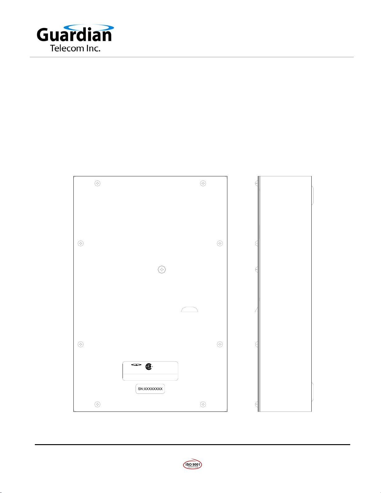
See: Figure 1 - SIA
Features and
Dimensions
•Ensure that none of the electrical connection circuits are live.
•Use the template provided to locate and drill holes for mounting screws. See: Insert - Template
•Remove the screws on the faceplate and remove the faceplate.
•Secure the unit to the wall.
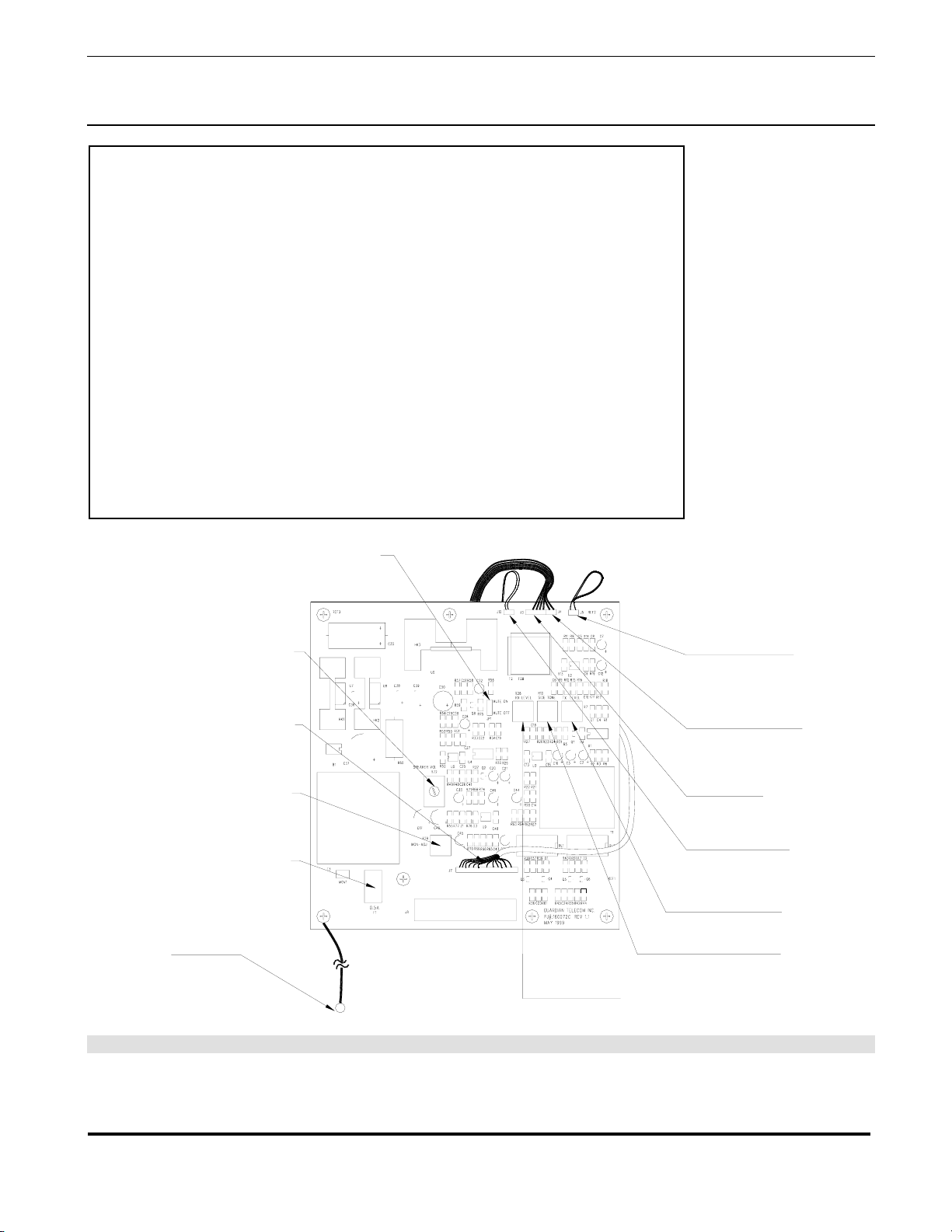
•Bring cable(s) into the enclosure through the conduit entrance(s) and attach
individual wires to the Combicon connector(s). Attach the first or only cable
to the bottom connector. Make connections to terminals 1A and 1B for a
single line system.
Note: Be careful when
removing the faceplate.
The circuit board is on
the faceplate.
See: Figure 3 - Electrical
Connections and Figure
4 - Wiring
•If the station is part of a Group Muting series connect the wires assigned to
this function to either the Mute or Park terminal on the connector. See: Group Muting
•Plug the connectors into the receptacles on the interface PCB.
•Ensure all connections are secure.
•Replace the faceplate ensuring that the connector is properly seated.
•Apply power to the system.
•Wait at least 20 seconds then adjust the speaker volume to the desired
level using the potentiometer accessible through the faceplate. Use the
tamperproof screwdriver provided to remove the screw and a small flat tip
screwdriver to make the adjustment.
•Test the installation by making a paging call.
Troubleshooting
Associated Speaker Is Not Working
•Ensure power is being supplied to the amplifier.
•Check the fuse located on the circuit board and replace if necessary.
Correct the problem that caused the fuse to fail.
•Remove power from the wall station.
See: Engineering
Specifications for correct
fuse rating
•Remove all faceplate cover screws.
•Lift off the faceplate cover.
•Replace the fuse.
•Replace the faceplate ensuring that the connector is properly seated.
Note: Be careful when
removing the faceplate.
The circuit board is on
the faceplate.
•Apply power to the wall station.
•Test the installation by making a paging call.

Guardian Telecom Inc.
Installation and Operation
Model SIA
Page 6
Electrical Connection Details
Assignment Designation Description Jacket Color Stripe Color
System Power J4A/J5A HOT Black
J4A/J5A COM White
J4A/J5A GND Green Yellow
Ambient Noise J6A MIC + n/a n/a
Microphone J6A MIC - n/a n/a
Speaker J7A SPK + n/a n/a
J7A SPK - n/a n/a
Page Line J2A/J3A PA Page Line Brown
J2A/J3A PB " White Brown
Channel J2A/J3A 1A Channel 1 Red
J2A/J3A 1B " White Red
J2A/J3A 2A Channel 2 Purple
J2A/J3A 2B " White Purple
J2A/J3A 3A Channel 3 Red Blue
J2A/J3A 3B " Blue Red
J2A/J3A 4A Channel 4 Yellow
J2A/J3A 4B " White Yellow
J2A/J3A 5A Channel 5 Blue
J2A/J3A 5B " White Blue
Group Muting of J2A/J3A Mute Orange
Loudspeakers J2A/J3A Park
Note: Channels 2 to 5 connections remain empty for a single line hookup.
Figure 3 - Electrical Connections
Figure 4 - Wiring
J6A AMBIENT NOISE
MICROPHONE
J2A/J3A PAGE AND
TALK CHANNELS
J7A EXTERNAL SPEAKER
CONNECTOR BOARD
MAIN CIRCUIT BOARD CONNECTOR

Guardian Telecom Inc.
Installation and Operation
Model SIA
Page 7
Ambient Noise Level Adjustment
The Ambient Noise Sensor on Guardian's Page/Talk stations automatically
adjusts the volume of the associated loudspeaker up to 10dB, so that pages
can be heard over the background noise.
There are two controls on the circuit board to adjust the Ambient Noise
Sensor mechanism. The Paging Speaker Volume Control – which is
accessible either from the faceplate or from the back of the module – sets
the volume of the speaker to a comfortable level when the ambient noise is
at a minimum. The Ambient Noise Monitor Adjustment Control determines
how the speaker volume tracks the ambient noise. That is if the speaker is
not loud enough with a high ambient noise the control can be adjusted to
increase the volume. Alternatively if the speaker is too loud with a high
ambient noise the control can be adjusted to decrease the volume. It is
usually not necessary to change the setting of the Ambient Noise Monitor
Adjustment Control since it is set at the factory for average conditions.
Adjustment could be necessary if for some reason the Ambient Noise Sensor
Microphone is shielded from the source of ambient noise or some similar
situation exists.
See: Figure 5 - Circuit
Board Layout
FUSE
120 VAC 0.5 AMP.
(2 AG FAST BLOW)
AMBIENT NOISE
MONITOR ADJUST
J7 FROM PAGE
LINE SWITCH
ADJUST
SPEAKER LEVEL
GROUND
POST
TRANSMITTER
LEVEL ADJUST
RECEIVER
LEVEL ADJUST
SIDE TONE
ADJUST
SPEAKER MUTE
J10 FROM
MICROPHONE
J4 FROM
HANDSET PAGE
SWITCH
J3 FROM
HANDSET
RX/TX
J5 FROM
HOOK SWITCH
Figure 5 - Circuit Board Layout

Guardian Telecom Inc.
Installation and Operation
Model SIA
Page 8
Group Muting
In order to avoid acoustical feedback it may be desirable in certain
circumstances to mute speakers associated with adjoining stations when
making a paging call. This can be accomplished by interconnecting the “Group
Mute” terminals of each station in the group, and setting the speaker mute
jumpers on the circuit boards to the appropriate position.
See: Figure 3 - Electrical
Connections and Figure
5 - Circuit Board Layout.
Note: Putting the mute jumper of a station in the on position will mute the
associated speaker when the page button is pressed. If the jumper is in
the off position the speaker will not be muted when the page button is
pressed.
If group muting is used the associated speaker of any station in the group with
its mute jumper in the on position will be muted when a paging call is made
from any station in the group, including the associated station. Any speaker
associated with a station with its mute jumper in the off position will not be
muted when a paging call is made from any station in the group, including the
associated station.
Note: Paging calls
originating from stations
outside the group will be
heard regardless of the
position of the Mute
jumper.
If it is desired to bypass a station in a group, connect the group paging wires to
the PARK terminals of that station.
EXAMPLE OF GROUP MUTING
STATION "A"
PARK
SIGNAL CONDUCTORS
GROUP MUTE
OFF
MUTE
STATION "B"
ON
STATION "C"
MUTE
JUMPER
If the Group Mute Signal Conductors are attached to the Park terminals of station “B” that station will be
bypassed and paging from stations “A” or “C” will have no effect on the output of the loudspeaker
associated with Station “B”.
If the Group Mute Signal Conductors are attached to the Mute terminals of station “B” the condition of
the loudspeaker associated with that station will depend on the setting of the Mute On/Off jumper. If
the jumper is in the ON position the loudspeaker will be muted if a paging call is made from any of the
three stations. If the jumper is in the OFF position the paging call will not be muted if a paging call is
made from any of the three stations.
Paging calls from outside the Group will always be heard, regardless of the position of the mute jumper.

Guardian Telecom Inc.
Installation and Operation
Model SIA
Page 9
Engineering Specifications
Electrical Requirements
INPUT VOLTAGE 24/120/240VAC, 24VDC
INPUT FREQUENCY 50/60HZ
INPUT VOLTAGE/CURRENT/FUSE 120VAC/0.1AMP/0.5A 20MM CERAMIC FAST BLOW
240VAC/0.05AMP/0.25A 20MM CERAMIC FAST BLOW
24VAC/VDC/0.5AMP/0.75A 20MM CERAMIC FAST BLOW
Speaker Amplifier
OUTPUT LEVEL 10 WATTS WITH NOMINAL VOLTAGE
AMPLIFIER GAIN 1.5VRMS AT RATED OUTPUT
FREQUENCY RESPONSE 250 –4000HZ
DISTORTION 1% MAXIMUM THD @1000HZ 10WATTS
INPUT IMPEDANCE 200K OHMS,NOMINAL
LOAD IMPEDANCE 4TO 16 OHMS (NOT LESS THAN 8OHMS FOR
CONTINUOUS SERVICE)
Environmental
WEATHER TIGHT ENCLOSURE GASKET
DUST TIGHT ENCLOSURE GASKET
Mechanical
BODY CONSTRUCTION 16 GAUGE STEEL,ZINC DICHROMATE PLATED AND
POWDER COATED
FACEPLATE STAINLESS STEEL
DIMENSIONS (H X WX D) 12.3 X 8.0 X 2.9 INCHES (313 X 203 X 74MM)
NET WEIGHT 11 LBS/5 KG
STANDARD MOUNTING VERTICAL WALL
CONNECTION FITTINGS CONDUIT OR CABLE GLAND
Compliance
CANADIAN STANDARDS ASSOCIATION CSA C22.2 NO.205M (SIGNAL EQUIPMENT)
CSA C22.2 NO.60950/UL60950 (SAFETY OF
INFORMATION TECHNOLOGY EQUIPMENT)

Guardian Telecom Inc.
Installation and Operation
Model SIA
Page 10
Warranty
Guardian Telecom warrants your product to be free of defects in material and workmanship for a period
of one year. Guardian Telecom will repair or replace any defective unit that is under warranty free of
charge.
This warranty is null and void if any non-authorized modifications have been made to this product, or if
it has been subjected to misuse, neglect, or accident. This warranty covers bench repairs only; such
repairs must be made at Guardian Telecom or an authorized service depot. Guardian Telecom is not
responsible for costs incurred for on-site service calls, freight, or brokerage.
A return authorization must be obtained prior to warranty claims or repairs.
Disclaimer
The products covered by this manual are designed for use in Industrial Environments and/or Hazardous
Locations. Due to the range of possible applications for these instruments the manufacturer will not be
responsible for damages or losses of any kind suffered as a result of the use of this product, including
consequential damages.
Warning
High voltages may be present in this product. Ensure that power is removed before installing,
performing maintenance or repairs.
Service Telephone Number
1-800-363-8010
Guardian Telecom provides a customer service telephone number which is toll-free within North
America. If you need assistance when installing or operating this product, please call the toll-free
telephone number between regular business hours (8:00AM-5:00PM), Mountain Standard Time. If you
are calling outside of regular business hours, please leave a detailed message, and a member of
Guardian Telecom’s Service Department will return your call as soon as possible. If your product
requires service, Guardian personnel will supply you with an RMA (return materials authorization)
number over the telephone or through our web site product return page. This number must be included
with your return address and the name of the person to contact.
Guardian Telecom Inc.
7000 Fisher Rd. SE
Calgary, Alberta, Canada
Toll-free 1-800-363-8010
Ph. (403) 258-3100
Fax. (403) 253-4967
www.guardiantelecom.com
Feedback
Guardian Telecom continually strives to make reliable, durable, and easy to use products. If you, as an
installer or user of our equipment, have any suggestions for improvements to this or any of our products
or documents, including this manual, we would appreciate hearing from you.

Guardian Telecom Inc.
Installation and Operation
Model SIA
Page 11
Guardian Product Return
Guardian products have been quality tested and are in full working order when shipped from the factory, given
the rugged nature of these products, shipping is not expected to damage a unit. In the unlikely event of a
malfunction, Guardian follows the three step procedure below.
Step I - On-Site Correction
•The most common source of difficulties with a new product is improper installation in one of two ways:
incorrect wiring connections or connection to an incorrect power source.
•Product wiring needs to be properly connected to the on-site wiring. Correct wiring instructions are shown in
the user manual included with the product.
•Connecting a telephone to a standard power source, rather than tip & ring, will blow the telephone’s internal,
user-replaceable fuse. In the event of fuse burn-out, disconnect the telephone from the power source,
replace the fuse, and reconnect following the wiring diagrams provided with the product.
Step II - Return Materials Authorization (RMA)
•When a product has been installed following user manual instructions, and the unit fails to operate, the user
must contact Guardian Telecom to obtain authorization to return the product. This can be done by
completing a RMA form online at www.guardiantelecom.com, or by calling the service telephone number
given in this manual.
•After providing information on the product, the owner and the nature of the problem, Guardian will issue a
RMA number, to be shown on documentation returned with the product.
•In addition to the RMA number, shipping documents should include name, address and telephone number
of the owner along with contact information for the person responsible for the repair and/or the user who
identified the malfunction.
•(Where a product is being returned for repair from outside of Canada, customs documentation must show
the product’s serial number, date of export [date of purchase], and a notation that the equipment is:
“Canadian goods returning.”)
Step III - Factory Authorized Service
•Once received, each product is carefully inspected and tested. If the product is under warranty, repairs are
completed and the product returned to the owner, generally within five working days of receipt by the
factory.
•A product that has been subjected to misuse, neglect or accident or is beyond the warranty period will be
evaluated. The service department will provide the owner’s representative with a repair cost estimate. Once
approved, repairs are completed and the product returned, generally within five working days.

Guardian Telecom Inc.
Installation and Operation
Model SIA
Page 12
Page/Talk Product Series Description
Guardian's Page/Talk Systems provide reliable and easy to use paging and communication within
industrial environments and hazardous locations, such as plants, mills and factories. Wall and desk
stations are available in both single line and multi line models. Individuals can be paged from any
station and two or more persons can communicate on any available line. With the addition of a
Merge/Isolate Cabinet up to 12 zones are supported.
These systems provide quality paging and communication functions, and with the telephone interface
unit, communication outside the system. Speaker amplifier units provide the capability of adding extra
speakers without the need for a Page/Talk station. The alarm tone generator provides synthesized
audio alarm signals for plant safety systems and can be programmed to activate strobe lights for
additional warning in noisy environments.
Guardian's Stations and related equipment are compatible with systems provided by most other
manufacturers.
Page/Talk System Models and Options
Standard Stations
P5901 SIP-1 Single Line Wall Station
P5906 SIP-5 Multi Line Wall Station
P5950 SIA Amplifier Unit
P5911 DTP-1 Single Line Desk Set
P5916 DTP-5 Multi Line Desk Set
P5921 WTP-1 Single Line Weather Proof Wall Station, NEMA 4X
P5926 WTP-5 Multi Line Weather Proof Wall Station, NEMA 4X
P5922 WTA Weather Proof Amplifier Unit, NEMA 4X
Hazardous Location and Explosion Proof Stations
P5900 SIP-H-1 Single Line Wall Station, Class I, Div.2
P5905 SIP-H-5 Multi Line Wall Station, Class I, Div.2
P5951 SIA-H Amplifier Unit, Class I, Div. 2
P5910 DTP-H-1 Single Line Desk Set, Class I, Div.2
P5915 DTP-H-5 Multi Line Desk Set , Class I, Div.2
P5920 WTP-H-1 Single Line Weather Proof Wall Station, NEMA 4X, Class I, Div.2
P5925 WTP-H-5 Multi Line Weather Proof Wall Station, NEMA 4X, Class I, Div.2
P5957 WTA-H Weather Proof Amplifier Unit, NEMA 4X, Class I, Div. 2
P5930 EXP-1 Explosion Proof Single Line Wall Station, Class I, Div.1
P5935 EXP-5 Explosion Proof Multi Line Wall Station, Class I, Div.1
P5956 EXA Explosion Proof Amplifier Unit, Class I, Div. 1
Options
P5940 PTI Telephone Interface Unit
P5980 PTL Line Balance Assembly
P5970 AG17 Alarm Tone Generator
P5960 AG17 Alarm Tone Generator, (with optional relay board.)
Cable
P005219 Standard 16 Conductor
P005366 Heavy Duty (Armoured) 16 Conductor
P00XXXX Standard 8 Conductor
P005863 Heavy Duty (Armoured) 8 Conductor

Guardian Telecom Inc.
Installation and Operation
Model SIA
Page 13
Appendix - Typical Layout
Hazardous Areas
CLEAR
GUARDIAN TELECOM INC.
CALGARY, ALBERTA, CANADA
-
Supply
Power
Max. 40VDC
120 / 240VAC
Line
Telephone
Interface
PTI
+
Unit
Balancing
Amplifier
Paging
SIA DTP
7000FisherRoadS.E
www.guardiantelecom.com
Fax:(403)2533-4967
Calgary,Alberta,CanadaT2H0W3
GuardianTelecom Inc.
Tel:(403)258-3100
22.214
Certified
entela
Certified
CSAc
c
CC057850
ExplosionResearch
780-905-9601
2
1
3
5
4
1
C
H
A
N
N
E
L
5
3
4
2
V
O
L
U
M
E
Environments
Industrial
MULTI-LINE PAGIN G WALLSTATION
ModelMLW15120 VAC, 60 HZ0.5amp.
GuardianTelecomInc.
SIP
Desk
Supply
Power
NORMALLY CLOSED
INPUT / OUTPUT
RELAY CONTACTS
COMMON
NORMALLY OPEN
Logic Pair
Run
+5V Run
Run Run
Busy
SUPPLY
POWER
COMMUNICATIONSSYSTEM
DIGITAL BUSINESS
PWR ON
48V
-5V Busy
Busy Busy
Relay
Switch
P.A.B.X.
Run Run R un Run Run
CONTROLLER
Busy B usy Busy Busy
SYSTEM
SERIAL
PORT2
PORT1
SERIAL
Busy
Audio Pair
Push to Talk
AG17 Alarm Tone Generator
L
INPUT
B
5
ALARM RELAY CONTACTS
RESET ABC CBA C AB ABC A
ALARM LOGIC OUT
C
-
+13254768
O/P
VOLUME
C-
+-
+
OUTPUT
AL
+-+
I/P A
1234
ACA CBBCBAC
6
ALARM LOGIC IN
-21435 C87C L
A
678
C
B
A
Fire & Gas
Alarm System
Button
Manual Push
Alarm Activation
S
U
FUSE 1A
LOGIC
AUDIO
SE
FU
120VAC
F
E
POWER
Hazardous Areas
Class I Div.1
4
2
1
5
3
4
1
2
3
5
Outdoors and
CSA Type 4X
High Humidity Areas
SIP-H
Class I Div.2
WTP
Cable
Custom
Guardian's
120/240 VAC
ExP
SR40

Guardian Telecom Inc.
Installation and Operation
Model SIA
Page 14
Notes:
Model No.
Part No.
Serial No.
Date of Purchase


Guardian Telecom Inc.
7000 Fisher Rd. SE
Calgary, Alberta, Canada T2H 0W3
Toll-free 1-800-363-8010
Ph. (403) 258-3100
Fax. (403) 253-4967
www.guardiantelecom.com
Industrial Communications Worldwide
© Guardian Telecom Inc. 2004
Table of contents