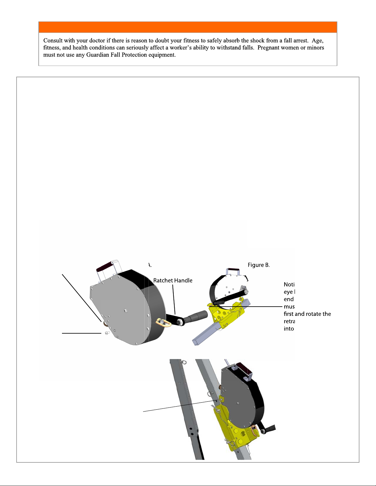
Guardian Arco Pod User manual

WARNING!
D
DO
ON
NO
OT
T:
:
•Do not alter or misuse this equipment.
•Do not use combinations of components or subsystems
that may affect or interfere with the safe, compatible
function of each other.
•Do not expose the equipment to chemicals which may
produce a harmful effect or degrade the equipment.
Consult manufacturer in cases where doubt exists.
•Do not use the equipment around moving machinery or
electrical hazards unless specifically designed for such
use.
•Do not use the equipment around sharp edges or
abrasive surfaces unless intended for such use.
DO NOT THROW AWAY THESE INSTRUCTIONS!
READ AND UNDERSTAND BEFORE USING EQUIPMENT!
This manual should be read and understood in its entirety, and used as part of a
training program as required by OSHA or any applicable state regulatory agency.
This and any other included instructions must be provided to the users of the
equipment. The user must understand the proper equipment use and limitations.
User must keep a copy of these instructions for reference and training.
This product meets all applicable OSHA and ANSI standards for fall protection.
G
GE
EN
NE
ER
RA
AL
LS
SY
YS
ST
TE
EM
MS
SE
EL
LE
EC
CT
TI
IO
ON
NC
CR
RI
IT
TE
ER
RI
IA
A:
:Selection of
fall protection shall be made by a Competent Person. All fall protection
equipment shall be purchased new and unused.
The equipment is designed for use as a part of a personal fall protection system.
Components shall not be used for any other operation other than that which it has
been designed and approved.
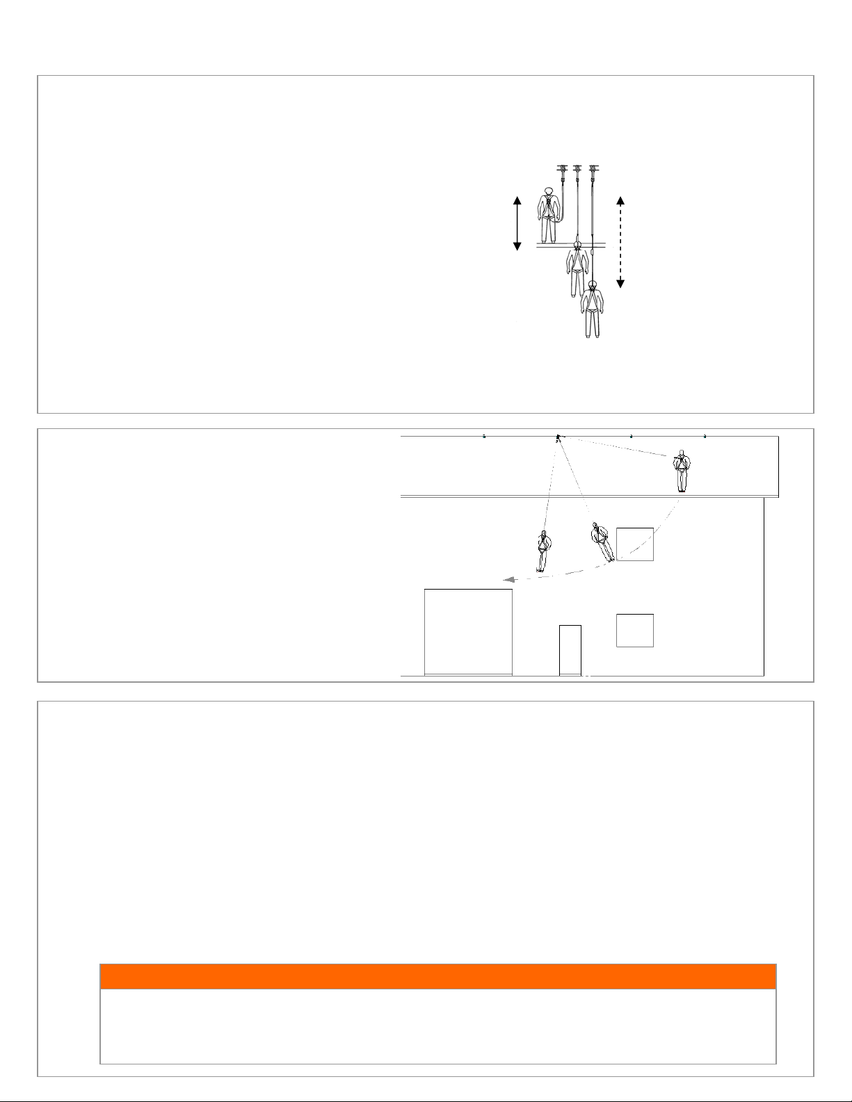
Fall Arrest Systems shall be designed to comply with OSHA or applicable state
regulatory limitations. Systems must be used in a compliant manner.
Fall Restraint systems shall be designed by a Qualified Person, and must be
installed and used under the supervision of a competent person.
Consult a doctor if there is any reason to doubt a user’s ability to withstand and
safely absorb fall arrest forces. Age, fitness, and health conditions can seriously
affect the worker should a fall occur. Pregnant women and minors should not
use this equipment.
T
TR
RA
AI
IN
NI
IN
NG
GR
RE
EQ
QU
UI
IR
RE
EM
ME
EN
NT
TS
S:
:The employer shall provide a training program for each employee who might be exposed to fall hazards. The
program shall enable each employee to recognize the hazards of falling and shall train each employee in the procedures to be followed in order to
minimize these hazards. Relevant Federal, State, and local regulatory requirements, procedures, and standards shall also be a part of training.
The employer shall ensure that each employee has been trained, as necessary, by a Competent or Qualified Person in the nature of fall hazards in the
work area, the correct erecting, maintaining, disassembling, and inspection of the fall protection systems being used, and the use of personal fall
arrest systems.
R
RE
ES
SC
CU
UE
EP
PL
LA
AN
N:
:The user is required to have a rescue plan and the means at hand to implement it when using the equipment. The plan shall be
project specific. Employees shall be trained in self-rescue or alternate means shall be provided for prompt rescue in the event of a fall.
I
IF
FE
EQ
QU
UI
IP
PM
ME
EN
NT
TI
IS
SS
SU
UB
BJ
JE
EC
CT
TE
ED
DT
TO
OA
AF
FA
AL
LL
L:
:Remove the equipment from service immediately if it has been subjected to the forces of a
fall arrest. Contact your distributor or Guardian about policies regarding replacement of Guardian components involved in a fall.
I
IN
NS
SP
PE
EC
CT
TI
IO
ON
N:
:
•Only the manufacturer of this equipment or persons or entities authorized in writing by the manufacturer shall make repairs to fall
protection equipment.
•Formal inspections shall be made by either a Competent or Qualified Person on at least a semi-annual basis.
P
PR
RI
IO
OR
RT
TO
OE
EA
AC
CH
HU
US
SE
E:
:
•Fall protection equipment shall be inspected by the user for defects, damage, or deterioration.
•Any suspected defective equipment shall be removed from service.
•If the manufacturer’s label is not legible or is missing, the equipment shall be removed from service. Fall protection equipment shall
be removed from service upon evidence of defects, damage, or deterioration, or upon expiration of the manufacturer’s specified
service limits, whichever comes first.
Arco Pod
Guardian Fall Protection Kent WA 98032
800.466.6385 www.guardianfall.com

OPERATION AND USE WITH SELF RETRACTING LIFELINES:
Setting up the tripod:
Step 1:
Step 2:
Step 3:
Step 4:
Place the collapsed tripod on the floor with the feet on the ground. Remove the denent pins from the top of the tripod
as shown in Fig. A.
Fully spread the legs and then replace the pins indicated in Fig. B. to secure the legs in the open position.
Remove all of the locking pins in Fig. B. from the adjustable legs. Resecure the pins in the tripod legs in the fully
extended position as shown in Fig. C.
**This system is much easier to install with two workers. In the case that you are setting up by yourself, lay the
tripod on its side to set up.
Place the tripod over the entry point. Adjust the tripod as necessary by removing the pin (Fig. C) in one leg at a time.
Adjust each leg so the tripod sits level above your entry point.Ensure that all deten pins are reinstalled
Step 4:
Place the tripod over the entry point. Adjust the tripod as necessary by removing the pin (Fig. C) in one leg at a time.
Adjust each leg so the tripod sits level above your entry point.Ensure that all deten pins are reinstalled
**This system is much easier to install with two workers. In the case that you are setting up by yourself, lay the
Place the tripod over the entry point. Adjust the tripod as necessary by removing the pin (Fig. C) in one leg at a time.
Adjust each leg so the tripod sits level above your entry point.Ensure that all deten pins are reinstalled
Place the tripod over the entry point. Adjust the tripod as necessary by removing the pin (Fig. C) in one leg at a time.
Adjust each leg so the tripod sits level above your entry point.Ensure that all deten pins are reinstalled
Fig. A. Fig. B.
Adjust each leg so the tripod sits level above your entry point.Ensure that all deten pins are reinstalled
Fig. C.
WARNING!
Remove all slack from the adjustment chain by loosening the quick connects at the feet of the tripod legs. Do
not use the Arco Pod if the chain is not present. Doing so may result in serious injury or even death!
Remove this pin and the 2 others in the
same location on the other two legs.
Remove detent pins to adjust
height of tripod. Ensure the pins
are replaced after adjusting legs
to desired height.
Ensure that
all locking
pins are in place
before use.
Remove all slack
from the adjustment
chain. Do not use if
there is slack or if
chain is not present.

WARNING!
OPERATION AND USE WITH SELF RETRACTING LIFELINES:
Installation of Guardian 3-WAY Retracable unit:
Step 1: Attach the 3-WAY SRL to the 3-WAY Tripod Bracket by first removing the two plastic screws from the SRL. Then
slide the swivel eye into the hook on the bracket andthen slide the 3-WAY SRL into the bracket cradle.
Step 2: Check to insure that the crank handle on the 3-WAY SRL has free range of motion and does not interfere with any
other object.
Step 3: Check that the SRL operates smoothly in both directions.
To Lower the Cable: Pull (Figure A.) outward on the locking pin and hold. Rotate the ratchet handle until it slides
outward and stops in the engaged position. Release the pin so that it falls into the locking position. Rotate the crank
handle in counter clockwise direction. If a fall has been arrested and lowering is required, first crank in the upward,
clockwise, direction for one half rotation. Now reverse the direction, counter clockwise, to begin lowering. A
minimum of 75lbs is required for lowering.
To Raise the Cable: Pull outward on the locking pin and hold. Rotate the ratchet handle until it slides outward and
stops in the engaged position. Release the pin so that it falls into the locking position. Rotate the crank handle
eh te t a t o ro ty r a s secenebyamt i ,me t sysyr evoce reh tegagneo t : e t oN. gn i suoheh to t n ie l baceh tkna r co tes iwkco l c
crank slightly. **CHECK THAT THE RATCHET HANDLE ENGAGES AND OPERATES THE WINCH
CORRECTLY.
Step 4:
Once the 3-WAY is cradled in the bracket, insert the two screws that are supplied with the bracket. These screws
fasten into the standoff in the SRL. DO NOT USE THE PLASTIC SCREWS. These holes are located under the
plastic screws on the handle side of the retractable. Do not overtighten the screws.
•
•
Tighten screws down
on both sides ensuring
to not overtighten.
Plastic screw:
Remove one on
each side in same
location.
Notice how the swivel
eye hooks around the
end of the bracket. You
must attach this end
retractable downward
into the cradle.
Locking Pin
Figure A. Figure B.
Ratchet Handle
Notice how the swivel
eye hooks around the
end of the bracket. You
must attach this end
retractable downward
into the cradle.
into the cradle.
Figure A.
Figure B.
Ratchet Handle
Fig. C.

Step 5: Attach the 3-WAY SRL and Bracket assembly to the tripod leg that contains the pulley on the top
of the tripod. Only install the 3-WAY BRACKET to the outside of the leg There are two options for
installing the 3-WAY SRL to the retractable leg based on how high you have adjusted the tripod.
Installation #1 shows the 3-WAY bracket attached to the larger diameter of the tripod leg. Note the .
pin configuration. This is used when the tripod is at full extension. Installation #2 shows the tripod
at a lowered height. These different attachment points will allow you to adjust the 3-WAY SRL
to your desired height for handle clearance when lifting a worker. Take note of where the pins
attach to the tripod leg. When pinning the bracket against the smaller diameter leg, you
must use the through hole which is closest to the leg to secure the bracket.
Step 6: Run the snaphook from the SRL up and over the pulley. You will need to remove the detent pin, shown in
Figure A, over the pulley to maneuver the cable through the pulley and down through the center opening as
shown in Figure A. Once cable is run over the pulley, replace the detent pin. Your assembled unit should look
like Figure B.
Step 7:
Pin #1 Pin #2 Pin #1 Pin #2
Installation #1 Installation #2
Fig. B.
Detent Pin
Fig. A.
Attach the snaphook end of the retractable to the dorsal D-Ring of your harness. Do not connect to any other
conection point on the harness unless that attachment point is rated for fall arrest.

WARNING!
L
La
ar
rg
ge
e
t
th
hr
ro
oa
at
t
o
op
pe
en
ni
in
ng
g
s
sn
na
ap
p
h
ho
oo
ok
ks
s
s
sh
ho
ou
ul
ld
d
n
no
ot
t
b
be
e
c
co
on
nn
ne
ec
ct
te
ed
d
t
to
o
s
st
ta
an
nd
da
ar
rd
d
s
si
iz
ze
e
D
D-
-r
ri
in
ng
gs
s
o
or
r
s
si
im
mi
il
la
ar
r
o
ob
bj
je
ec
ct
ts
s
w
wh
hi
ic
ch
h
w
wi
il
ll
l
r
re
es
su
ul
lt
t
i
in
n
a
a
l
lo
oa
ad
d
o
on
n
t
th
he
e
g
ga
at
te
e
i
if
f
t
th
he
e
h
ho
oo
ok
k
o
or
r
D
D-
-r
ri
in
ng
g
t
tw
wi
is
st
ts
s
o
or
r
r
ro
ot
ta
at
te
es
s.
.
L
La
ar
rg
ge
e
t
th
hr
ro
oa
at
t
s
sn
na
ap
p
h
ho
oo
ok
ks
s
a
ar
re
e
d
de
es
si
ig
gn
ne
ed
d
f
fo
or
r
u
us
se
e
o
on
n
f
fi
ix
xe
ed
d
s
st
tr
ru
uc
ct
tu
ur
ra
al
l
e
el
le
em
me
en
nt
ts
s
s
su
uc
ch
h
a
as
s
r
re
eb
ba
ar
r
o
or
r
c
cr
ro
os
ss
s
m
me
em
mb
be
er
rs
s
t
th
ha
at
t
a
ar
re
e
n
no
ot
t
s
sh
ha
ap
pe
ed
d
i
in
n
a
a
w
wa
ay
y
t
th
ha
at
t
c
ca
an
n
c
ca
ap
pt
tu
ur
re
e
t
th
he
e
g
ga
at
te
e
o
of
f
t
th
he
e
h
ho
oo
ok
k.
.
ATTACH TO OVERHEAD
ANCHORS!
SWING FALLS INCREASE
FALL ARREST DISTANCE.
• Capacity: The SRL is for use by one person with a combined weight (person, clothing, tools, etc.) of 75lbs. minimum and
310lbs. maximum.
Consider When Calculating Distance:
• Deceleration Distance
• Movement of harness attachment
element (D-ring)
• Free Fall Distance
• Worker Height (how tall the worker is
could affect the free fall distance)
• Elevation of Anchorage Connector
• Connecting Subsystems Length
APPLICABLE STANDARDS:
Refer to potential applicable standards. Standards might include OSHA regulations depending on the type of work, and also might include state regulations if
applicable. Consult regulatory agencies for more information on personal fall arrest systems and associated components. This product is designed to comply with
OSHA and ANSIZ359.1 standards when used properly, and in accordance with manufacturer’s instructions.
LIMITATIONS CONTINUED:
• Swing Falls: Swing falls occur when the anchorage point is not
directly above the point where a fall occurs. The force of striking an
object in a swing fall may cause serious injury or death. Minimize
the risk of swing falls by working as close to the
anchorage point as possible. Do not permit a swing fall if
injury could occur. Swing falls will significantly
increase the clearance required when a self retracting
lifeline or other variable length connecting system is
used.
• Potential Environmental Hazards: Use of fall protection
equipment in areas with environmental hazards may require
additional precautions to prevent injury to the user or damage to the
equipment. Hazards may include but are not limited to: chemicals,
corrosive environments, high voltage power lines, gases, moving
machinery, and sharp edges.
SYSTEM REQUIREMENTS:
• Compatibility of Components: Guardian Fall Protection equipment is designed to be used with Guardian approved
components. Please contact Guardian if you have a question regarding compatibility. Making substitutions without approval
from Guardian Fall Protection may lead to injuries and or death by compromising the safety and reliability of the complete
system. A Qualified person can make a determination on compatibility of equipment from different manufacturers. If in
doubt, please contact Guardian Fall Protection for clarification.
• Compatibility of Connectors: Connectors (D-rings, hooks, carabiners) must be capable of supporting at least 5,000 lbs.
(22kN). Do not use equipment that is not compatible. Non-compatible connectors may unintentionally disengage. Self
locking snap hooks and carabiners are required by ANSI and OSHA. Connectors must be compatible in size, shape, and
strength.
• Making Connections: Only use self-locking snap hooks and carabiners with any Guardian Fall Protection equipment. Do not
use equipment that is not compatible. If you have any questions on compatibility, please call Guardian Fall Protection at
800.466.6385.
Total Fall Distance
(Free Fall + Deceleration Distance)
6 Feet Max
Free Fall

WARNING!
Do not alter or intentionally misuse this equipment. Consult with GFP when using this equipment in
combination with components or subsystems other than those described here in this manual and or other
information. Use caution when using this equipment around moving machinery, electrical and chemical
hazards, and sharp edges.
PERSONAL FALL ARREST INFORMATION:
•Personal Fall Arrest System (PFAS): Personal fall arrest systems used with this equipment must meet applicable state,
federal, OSHA, and ANSI requirements. A full body harness must be worn when this equipment is used as a component of a
personal fall arrest system. As required by OSHA, the personal fall arrest system must be capable of arresting the user’s fall
with a maximum arresting force of 1,800 lbs., and limit the free fall to six feet or less.
WARNING!
I
If
fi
in
ns
sp
pe
ec
ct
ti
io
on
nr
re
ev
ve
ea
al
ls
sa
an
nu
un
ns
sa
af
fe
eo
or
rd
de
ef
fe
ec
ct
ti
iv
ve
ec
co
on
nd
di
it
ti
io
on
n,
,r
re
em
mo
ov
ve
et
th
he
ep
pr
ro
od
du
uc
ct
tf
fr
ro
om
ms
se
er
rv
vi
ic
ce
ea
an
nd
ds
se
en
nd
dp
pr
ro
od
du
uc
ct
tb
ba
ac
ck
kt
to
o
G
Gu
ua
ar
rd
di
ia
an
nF
Fa
al
ll
lP
Pr
ro
ot
te
ec
ct
ti
io
on
no
or
ra
aG
GF
FP
Pa
au
ut
th
ho
or
ri
iz
ze
ed
ds
se
er
rv
vi
ic
ce
ec
ce
en
nt
te
er
r.
.
INSPECTION OF THE ARCO POD TRIPOD:
•Before each use of this equipment inspect it according to the following guidelines:
A formal inspection of fall protection products/components must be performed at least every six months by a competent
person other than the user. The frequency of formal inspections should be based on conditions of use or exposure.
LIMITATIONS:
Consider the following application limitations before using this equipment.
•Capacity:
All connecting sub systems must limit fall arrest forces to under 1,800lbs.
The Arco Pod is designed to be used by a person that weighs no more than 310lbs. This includes all tools and clothing.
•Corrosion: Leaving the Arco Pod in an environment for long periods of time that could cause corrosion of metal parts is not
warranted in any way and must not be done. Use caution when working around corrosive compounds such as ammonia,
sewage, fertilizers, seawater or other corrosive environments, may require more frequent inspections or servicing. These
increased inspections and servicing are required to ensure corrosive damage is not impacting the performance of the Arco Pod.
•Chemical Hazards and Heat: When using a self retracting lifeline in conjunction with the Arco Pod, Extreme caution must be
taken when working in or around environments containing acid or caustic chemicals, particularly at elevated temperatures.
Damage will be caused to the self retracting lifeline in this environment. Chemical damage is difficult to detect and it is
recommended that the lifeline be replaced periodically to ensure safety of the workers. Keep the tripod’s exposure to extreme
heat and cold to a minimum. Avoid accumilation of slag and other material build up on the Arco Pod.
r •Electrical Hazards: When using a self retracting lifeline, the possibility of an electric current flowing through the lifeline.
Moisture absorbed by the lifeline may provide a path for electrical current to flow, resulting in electrical shock. Use caution
where the lifeline or tripod may contact high voltage power lines.
•Locking Speed: Extreme caution should be taken when using this device whereas an obstructed fall could occur as well as
when someone must perform work in a confined or cramped space. Working in these types of environments could limit the
speed at which the locking mechanisms engage. A clear path is required to ensure positive locking of the SRL.
DESCRIPTION OF PRODUCT:
ARCO POD: All Guardian Tripods are meant for use in confined space applications and meet all applicable ANSI and OSHA standards. The Tripods can be
used with a standard anchorage connector when connecter to the hard point on the tripod. You may also use the tripod in conjunction with a
Guardian SRL 3-WAY retrieval unit. The tripods are meant to ease in the entry and exit of confined space environments.
GUARDIAN ARCO POD: The Guardian Arco Pod comes with 3 locking pins at the head of the tripod, 3 locking pins located on the legs of the tripod,
1 pin over the pulley and 1 adjustable chain attached to the feet of the tripod. Make sure all of these parts are present before use of the tripod. Contact
Guardian for replacement parts.
PRODUCT APPLICATION INFORMATION:
The SRL 3-WAY is used in a stationary manner. As a stationary device, the SRL would be mounted to an approved fixed anchorage connector
dire
3-WAY Bracket. The 3-WAY retractable can also be attached to a retractable using the static anchor points at the peak of the tripod.`
ctly overhead. Applications of an approved anchor include mounting to the Guardian Fall Protection 04102 Arco-Pod using the 10983

WARNING!
CABLE INSPECTION WHEN USING WITH A SELF RETRACTING LIFELINE:
When inspecting SRL’s that utilize cable lifelines, it is critical to look for the following damages and deterioration that will result
in malfunction of the unit and potentially unsafe conditions.
Crushing: The cable will often get crushed or bent while being used on a job site. Cable that is crushed or bent will damage
the retractable and thus the unit should be immediately taken out of service and returned to Guardian or an authorized repair
center.
Cutting: Movement over sharp edges or other objects while the cable is under tension can result in damaged strands and
broken wires. If, through inspection of the retractable lifeline prior to each use, it is found to have any broken strands,
immediately remove from service and return to Guardian or an authorized repair center.
Abrasion: Abrasion can result from normal wear. Particular attention must be paid to the outer wire strands as they will
appear to be flattened and or shiner than other parts of the cable. If, through inspection of the retractable lifeline prior to each
use, it is found have damage or deterioration from abrasion, immediately remove from service and return to Guardian or an
authorized repair center.
Kinking: Any deformation in the cable whereas the lifeline appears to be bent, requires the retractable to be immediately
removed from service and returned to Guardian or an authorized repair center.
Corrosion, Arc or Heat Damage: Extreme caution must be taken to avoid any potential damage as a result of using a
retractable within an environment where corrosive compounds, welding, or high heat may exist. Corrosive damage could
cause the cable to crack. Welding damage would result in fused wires and thus change the characteristics of the strength with
regards to the wire. If the retractable is used in these environments, the retractable lifeline needs to be closely examined for
damage. If you have any questions in terms of damage to the retractable or further explanation of the above information is
needed, please call 1-800-466-6385.
•Annually: ANSI requires a formal inspection of the tripod be completed by a competent person other than the user at least
twice a year. More formal and frequent inspections maybe required based upon the severity and environmental conditions of
the workplace. Guardian Fall Protection Retractables, unless otherwise marked, are required to be recertified every two years
from the date of first use.
•After a Fall Arrest:
deformation that may have occured. Look over the hard point if connected with a standard self retracting lifeline. Look over
the 3 way bracket and its mounting location for cracking or deformation. Visually inspect all hardware for bending or fatigue.
Inform your onsite safety director that a fall has occurred on this equipment.
Inspect the structure of the tripod. Look over the leg structure for bends or cracks and any other
Inspecting the ARCO POD:
Step 1. Inspect for missing pins and bent or damaged parts.
Step 2. Inspect legs for distortion, cracks or other damage. Ensure the pulley moves freely and is not distorted or cracked
in any way.
Step 3. The legs must fully extend and collapse in order to use properly
Step 4. Ensure the adjustable chain is secured to all feet and all slack is removed by adjusting the quicklinks.
Step 5. The labels must be present and fully legible with inspection log information completed.
Step 6. Look for signs of corrosion on the entire unit.
Step 7. Inspect connecting hooks or carabiners for signs of damage, corrosion or excessive wear.
Step 8. Record inspection results in the inspection and maintenance log found in this manual.

WARNING!
PLAN THE FALL PROTECTION SYSTEM:
Before installation plan your system. Consider all factors that will affect your safety during use of this equipment. The following
list gives important points to consider when planning your system:
Anchorage: Select a rigid anchorage capable of supporting the loads no less than 5,000 lbs. per worker attached.
Sharp Edges: Avoid working where system components may be in contact with, or abrade against, unprotected sharp edges.
After a Fall: Components which have been subjected to the forces of arresting a fall must be removed from service and
destroyed. Retractables must be returned for servicing to GFP or an authorized repair center.
Rescue: The employer must have a rescue plan when using this equipment. The employer must have the ability to perform a
rescue quickly and safely.
WARNING!
I
If
fi
in
ns
sp
pe
ec
ct
ti
io
on
nr
re
ev
ve
ea
al
ls
sa
an
nu
un
ns
sa
af
fe
eo
or
rd
de
ef
fe
ec
ct
ti
iv
ve
ec
co
on
nd
di
it
ti
io
on
n,
,r
re
em
mo
ov
ve
et
th
he Arco Pod
e Arco Pod f
fr
ro
om
ms
se
er
rv
vi
ic
ce
ea
an
nd
ds
se
en
nd
db
ba
ac
ck
kt
to
oG
Gu
ua
ar
rd
di
ia
an
n
F
Fa
al
ll
lP
Pr
ro
ot
te
ec
ct
ti
io
on
no
or
ra
an
na
au
ut
th
ho
or
ri
iz
ze
ed
dr
re
ep
pa
ai
ir
rc
ce
en
nt
te
er
r.
.
WARNING!
T
Tr
ra
ai
in
ni
in
ng
gs
sh
ho
ou
ul
ld
db
be
ec
co
on
nd
du
uc
ct
te
ed
dw
wi
it
th
ho
ou
ut
te
ex
xp
po
os
si
in
ng
ga
an
ny
yo
on
ne
et
to
oa
af
fa
al
ll
lh
ha
az
za
ar
rd
d.
.T
Tr
ra
ai
in
ni
in
ng
gs
sh
ho
ou
ul
ld
db
be
er
re
ep
pe
ea
at
te
ed
do
on
na
ap
pe
er
ri
io
od
di
ic
c
b
ba
as
si
is
si
in
na
ac
cc
co
or
rd
da
an
nc
ce
ew
wi
it
th
hy
yo
ou
ur
ro
or
rg
ga
an
ni
iz
za
at
ti
io
on
ns
sp
po
ol
li
ic
cy
ya
an
nd
dc
co
om
mp
pl
li
ia
an
nc
ce
ew
wi
it
th
hO
OS
SH
HA
Ar
re
eg
gu
ul
la
at
ti
io
on
ns
s.
.
INSTALLATION REQUIREMENTS:
The following requirements outline the proper installation procedures to be followed.
Location:
Select a location on an appropriate strength anchorage that will provide overall safety and proper loading. The anchorage
must be free of deformities or defects that may weaken the structure. The anchorage to which the tripod is placed must be
capable of sustaining static loads in the directions applied by the personal fall arrest systems of at least 3,600lbs with
certification of a qualified person, or 5,000lbs without certification.
Do not work above the anchorage point. While using an SRL, always ensure that there is constant tension on the cable.
Slack in the cable could result in an increase in fall distance. Move normally as sudden jerky movements will allow the
locking mechanism to engage.
Do not install in an area where a swing fall hazard potentially could exist. Failure to do so could result in injury or
possibly death.
Keep these instructions for reference.
TRAINING:
It is the responsibility of the user and the purchaser of this equipment to assure that they are familiar with these instructions,
trained in the correct care and use of, and are aware of the operating characteristics, application limits, and the consequences of
improper use of this equipment.
Table of contents
Other Guardian Camera Accessories manuals