GUIDANCE MARINE CyScan Manual

Guidance Marine Ltd, 4 Dominus Way, Meridian Business Park, Leicester LE19 1RP, UK
T:+44 116 229 2600 E: [email protected]
www.guidance.eu.com
www.marine.direct
CyScan Operator’s Guide
Featuring
CyScan Dashboard
W
A
R
R
A
N
T
Y
S
e
e
o
u
r
s
t
a
n
d
a
r
d
t
e
r
m
s
o
f
s
a
l
e
Q
U
A
L
I
T
Y
A
S
S
U
R
E
D
3
YEAR

l2
Guidance Marine Ltd,
4 Dominus Way
Meridian Business Park
Leicester
LE19 1RP
UK
Tel: +44 116 229 2600
Tel (Customer Services): +44 116 229 2665
Email: [email protected]
Web: www.guidance.eu.com
Class 1 Laser Product
Complies with EN 60825-1
Complies with USA CFR 1040.10 & 1040.11
except for deviations pursuant to Laser Notice
No 50 26 Jul 2001
CLASS 1
LASER PRODUCT
CyScan Operator’s Guide
Issue Date: 28/08/2015.
Document No: 94-0353-4-D
Copyright © 2015 Guidance Marine Limited. All Rights Reserved.
Copyright in the whole and every part of this document belongs to Guidance Marine
Limited (the “Owner”) and may not be used, sold, transferred, copied or reproduced in
whole or in part in any manner or form or in or on any media to any person other than
in accordance with the terms of the Owner’s Agreement or otherwise without the prior
written consent of the Owner. "CyScan” is a registered trademark of Guidance Marine
Ltd. All the other brand or product names are trademarks or registered trademarks of
their respective companies or organisations.
Serial No:
Date of Shipment from UK:
Sensor Software Version: Dashboard Software Version:

l3
Table of Contents
Introduction................................................................................................... 5
Welcome�����������������������������������������������������������������������������������������������������������������������6
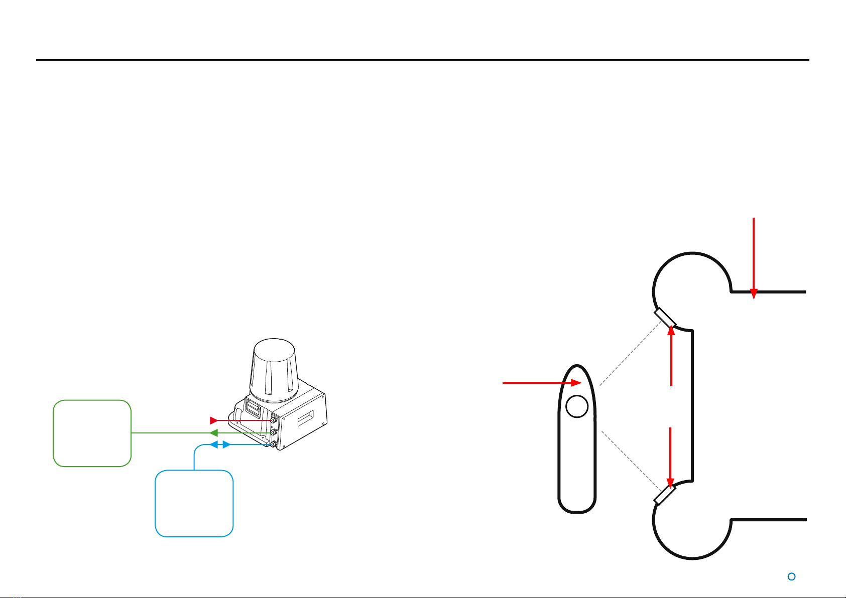
System Overview����������������������������������������������������������������������������������������������������������7
CyScan Sensor Part Names�����������������������������������������������������������������������������������������8
Getting Started............................................................................................ 9
Start Up and Shut Down ��������������������������������������������������������������������������������������������10
Start Up �����������������������������������������������������������������������������������������������������������������������������������������������10
Shut Down������������������������������������������������������������������������������������������������������������������������������������������� 10
Screen Layout ������������������������������������������������������������������������������������������������������������11
Main Screen and Bird's Eye View (BEV) ����������������������������������������������������������������������������������������������12
Side Bar�����������������������������������������������������������������������������������������������������������������������������������������������14
Hotkey Buttons������������������������������������������������������������������������������������������������������������������������������������15
Menu Pane ������������������������������������������������������������������������������������������������������������������������������������������ 16
Coordinates View���������������������������������������������������������������������������������������������������������������������������������17
Tracking Information Quality���������������������������������������������������������������������������������������18
Display Settings����������������������������������������������������������������������������������������������������������19
Vessel Orientation�������������������������������������������������������������������������������������������������������20
Tracking Basics ........................................................................................ 21
Blanking Zones�����������������������������������������������������������������������������������������������������������22
Setting the Blanking Zone ������������������������������������������������������������������������������������������������������������������� 22
Working with Reections��������������������������������������������������������������������������������������������23
Basic Refections Data �������������������������������������������������������������������������������������������������������������������������23
Extended Reection Data��������������������������������������������������������������������������������������������������������������������24
Scanner Tilt Controls��������������������������������������������������������������������������������������������������25
Scanner Tilt Modes������������������������������������������������������������������������������������������������������������������������������ 25
Manually Tilting the Scanner ���������������������������������������������������������������������������������������������������������������26
Spirit Level������������������������������������������������������������������������������������������������������������������������������������������� 26
Single and Multi-Target Tracking ...................................................... 27
Introduction to Single and Multi-Target Tracking �������������������������������������������������������28
To Start Tracking ���������������������������������������������������������������������������������������������������������������������������������� 28
To Stop Tracking ���������������������������������������������������������������������������������������������������������������������������������� 28
Positional Display Modes �������������������������������������������������������������������������������������������29
Bow and Starboard Axes��������������������������������������������������������������������������������������������������������������������� 30
A and B Axes (A Pos and B Pos) ��������������������������������������������������������������������������������������������������������� 30
Selecting Targets for Multi-Target Tracking ����������������������������������������������������������������31
Selecting Reections���������������������������������������������������������������������������������������������������������������������������31
Target Selection Order�������������������������������������������������������������������������������������������������������������������������32
Target Selection Order and Coordinate Axes Direction�����������������������������������������������������������������������33
Axis Orientation and Vessel Heading �������������������������������������������������������������������������34
Target Orientation in Respect to Axis A����������������������������������������������������������������������������������������������� 34
Vessel Heading ������������������������������������������������������������������������������������������������������������������������������������ 35
Rotational Offsets�������������������������������������������������������������������������������������������������������36
Axis Orientation and Vessel Heading Examples ����������������������������������������������������������������������������������37
Aligning Multi-Target Heading with the Ship’s Compass���������������������������������������������������������������������40
Multi-Dashboard (Ethernet) CyScan Systems ............................. 41
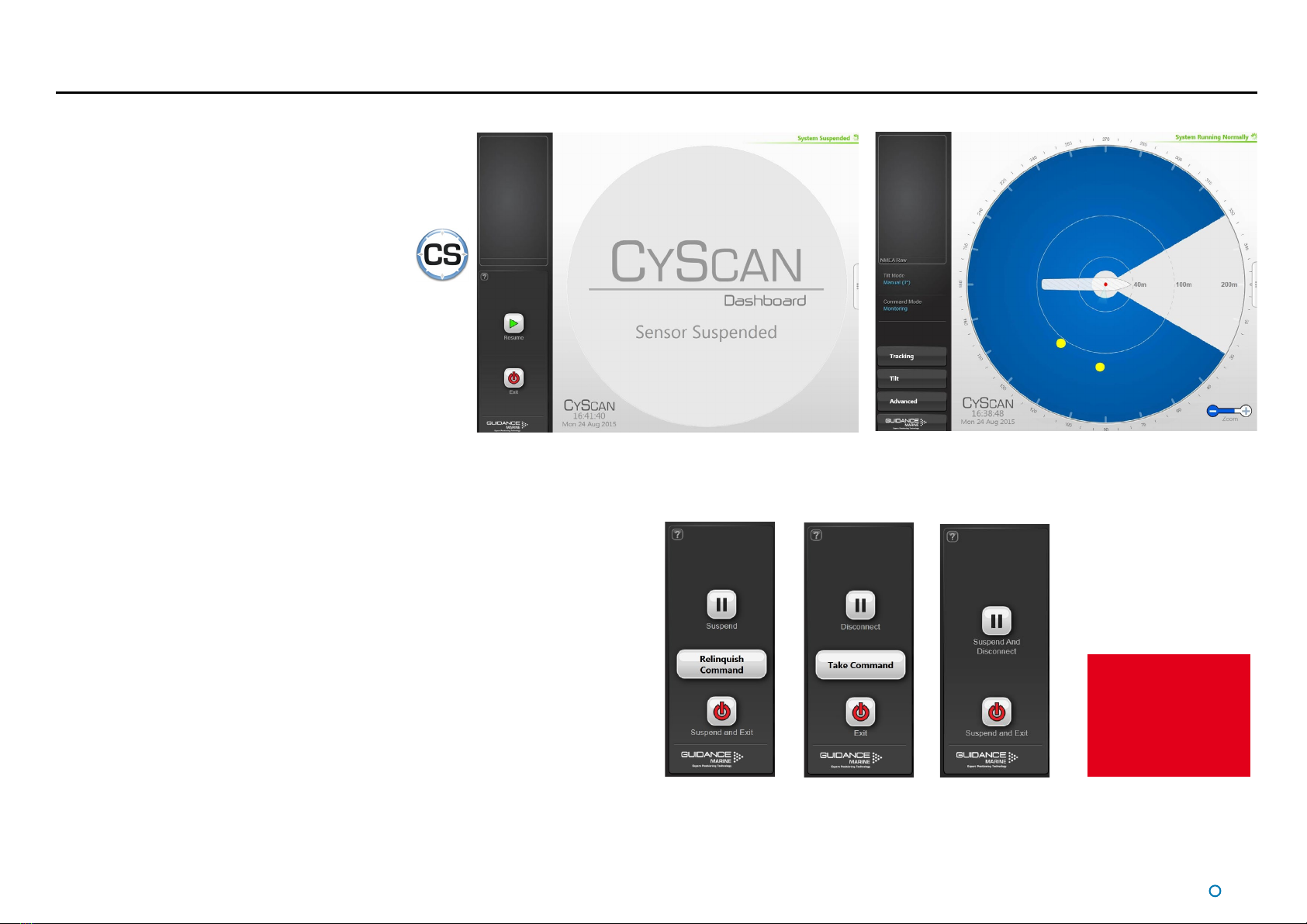
CyScan Ethernet Dashboard - Monitoring Mode�������������������������������������������������������42
CyScan Ethernet Dashboard - In Command Mode ���������������������������������������������������43
Support Information ............................................................................... 44
Serial Numbers and Software Versions����������������������������������������������������������������������45
DP Feed����������������������������������������������������������������������������������������������������������������������46
To View DP Feed Details:���������������������������������������������������������������������������������������������������������������������46
Manual Power Control������������������������������������������������������������������������������������������������47
To Enable Manual Power Control: �������������������������������������������������������������������������������������������������������47
To Use Manual Power Control:������������������������������������������������������������������������������������������������������������47
To Disable Manual Power Control: ������������������������������������������������������������������������������������������������������47
Data Logging��������������������������������������������������������������������������������������������������������������48

l4
Table of Contents (Continued)
Troubleshooting........................................................................................ 49
Problems and Possible Remedies������������������������������������������������������������������������������50
Cleaning the Sensor and Targets �������������������������������������������������������������������������������51
CyScan Fuse Information�������������������������������������������������������������������������������������������52
Additional Information ........................................................................... 53
Targets-Installation and Position ��������������������������������������������������������������������������������54
Low Temperature Operation���������������������������������������������������������������������������������������56
Using the On Screen Keyboard����������������������������������������������������������������������������������57
Working with Alarms���������������������������������������������������������������������������������������������������58
Filtering Alarms������������������������������������������������������������������������������������������������������������������������������������ 58
Using the Historic Alarm List ��������������������������������������������������������������������������������������������������������������� 59
Network Communications Settings����������������������������������������������������������������������������60
CyScan System Specications ����������������������������������������������������������������������������������61
Index���������������������������������������������������������������������������������������������������������������������������62
Document History ������������������������������������������������������������������������������������������������������64

l6
Welcome
Welcome to the CyScan (Dashboard) Operator's Guide. It has been written for operators
of the CyScan system that use the CyScan Dashboard operator interface rather than the
legacy CyScan Console.
Getting Started (see page 9) explains the basics that you’ll need to know before using
the CyScan system for the first time.
The CyScan system can be installed either as a single-Dashboard serial system or as a
multi-Dashboard Ethernet system.
The majority of the sections in this guide apply equally for serial or Ethernet configured
systems and explain how to perform the various tasks necessary to operate the system
and use it for tracking. These include Tracking Basics (see page 21) and Single
and Multi-Target Tracking (see page 27), Support Information (see page 44) and
Troubleshooting (see page 49). The section Multi-Dashboard (Ethernet) CyScan
Systems (see page 41) gives information specific to an Ethernet configured system.
Note that whilst we endeavour to describe the functionality of the Dashboard correctly in
this document, we do not guarantee that it exactly represents the version of Dashboard
that you are running, particularly after any future upgrades to the software.

The CyScan System is based on a high accuracy laser sensor and provides positional
information to allow automated approach and/or station keeping relative to a structure or
vessel. It requires one or more reflective targets to be attached to the sides of the structure
or vessel.
The CyScan system is designed to be semi-portable and straightforward to operate. Its
key elements are:
• The CyScan Sensor, with integrated Power Supply Unit, which is mounted on the
vessel (typically on the wheel-house) as required.
• The CyScan Client Software: The CyScan Dashboard is a monitoring and control
application running within Microsoft WindowsTM on a Type 2 Marine Processor or
other computer. This provides the DP operator with status information and control of
the system and the data stream being fed to the DP system. The CyScan Service
Interface is used for system installation and maintenance. This replaces the Service
Access function in earlier versions of the CyScan Dashboard and Console.
• The CyScan Targets. Retro-reflectors consisting of high performance reflective
tape mounted on a flat or cylindrical support, or – for longer-range capability – prism
clusters.
C
l7
System Overview
CyScan emits eye-safe infra-red light and detects the reflections received back from one or
more targets mounted on designated structures or vessels. The range and bearing of the
target(s) are accurately measured, displayed on the Dashboard screen and automatically
transmitted to the vessel's DP system.
CyScan
Vessel
CyScan
Targets
Structure
or Vessel
CyScan
Sensor
DP
System
Client
Software
Computer(s)
Power
The key elements of the CyScan system

l8
CyScan Sensor Part Names
The diagram below illustrates various parts of the sensor unit and gives the terms used for them.
Client Data
Power
DP Feed
Optical Window
Rotor
Base Plate
Sensor Information
Display
Access Plate
Cable Gland Plate

l9
Getting Started
This section contains the following pages:
• Start Up and Shut Down (page 10)
• Screen Layout (page 11)
• Tracking Information Quality (page 18)
• Display Settings (page 19)
• Vessel Orientation (page 20)
You may also find the following sections of the Appendices useful at this stage:
• Using the On Screen Keyboard (page 57)
• Working with Alarms (page 58)

Dashboard screen with sensor suspended Dashboard screen with sensor scanning
Dashboard
In Command
Dashboard
Monitoring
Serial
Dashboard
l10
Start Up and Shut Down
Start Up
To Start CyScan Dashboard
1. Ensure that the CyScan sensor is powered on.
2. Double-click on the CyScan Dashboard icon.
(Or run the CyScan Dashboard application from
Start > All Programs > Guidance Marine Ltd >
CyScan > CyScan Dashboard).
3. The Dashboard display screen will appear.
If the sensor is currently suspended, the main part of
the screen will be greyed out. Click on the Resume
button in the side bar in order for the sensor to begin
scanning and for the results to be displayed on the
screen. If the sensor was already scanning, any targets
in view will be displayed straight away.
Shut Down
To Suspend, Exit or Disconnect
1. Click on the Guidance button in the lower left corner of the screen
This will reveal buttons in the side bar as follows: (see right).
• Suspend - Places the sensor into a ‘sleep mode’. The rotor ceases spinning and the
scanner tilt returns to a fixed state. However, upon command from the Dashboard
application, the unit will return to full operation. This mode is suitable for use when
travelling between locations.
• Disconnect - Ceases communications between the Dashboard and sensor and
causes the main part of the screen to be greyed out. Does not cause the sensor to
stop spinning or tracking targets.
• Suspend And Disconnect – A combination of the above two functions (Serial
Dashboard only).
• Suspend And Exit - Places the sensor into the same ‘sleep mode’ as the suspend
command (discussed above) and also closes the CyScan Dashboard program.
• Exit - Closes down the Dashboard without affecting the sensor.
See Multi-Dashboard
(Ethernet) CyScan
Systems (page 41)
for information on In
Command/Monitoring
functionality.

l12
Main Screen and Bird's Eye
View (BEV)
The centre of the circular BEV represents
the CyScan sensor and it shows the relative
positions of the CyScan vessel and any detected
reflections.
Vessel Outline
The length and breadth of the vessel and the
offsets and orientation of the CyScan sensor
within it can be configured using the CyScan
Service Interface (see Installer's Guide) so
that the vessel image is correctly scaled and
positioned on the BEV.
Blanking Zone
The Blanking Zone is the sector within each
revolution of the sensor rotor where the laser is
switched off. It is typically set to correspond to
the area in which the beam would strike portions
of the vessel structure. The blanking zone can be
adjusted using the Drag Handles, to suit different
situations (See Blanking Zones on page 22).
Range Circles
The Range Circles act as a visual guide to show
the distance between the CyScan vessel and
the detected reflections. Distances are shown in
metres from the CyScan sensor. Use the Zoom
Control to change the scale of the display. (See
page 13).
Radial Markers
These form an angular scale in degrees,
clockwise around the circumference of the BEV.
Zero is defined by the bow of the vessel, or by a
line between the primary and secondary targets,
or by a manual alignment of vessel heading,
depending upon the selected tracking mode, DP
format and display coordinates.
Screen Layout (Continued)
Blanking Zone
Drag Handles
Vessel Outline
Range Circles
Blanking Zone
Reflection Images
Bearing Tag
Zoom Control
Hotkeys Tab
Status Display
Radial Markers Hotkeys Menu
Data Logging
Indicator
Heading Tag

l13
Screen Layout (Continued)
Reflection Images
Reflections received by the sensor are displayed as yellow circles. For tracking you
must select the reflection(s) that correspond to the physical target(s) to be used. During
multi-target tracking, grey boxes are drawn around the selected reflections to indicate a
strong association with the target (i.e. the system is receiving good data and is confident
of the target position). A red box appears around a selected reflection during tracking if the
system has lost sight of the target, or there is insufficient data being received to use it for
tracking.
Bearing and Heading Tags
These are displayed on the Radial Marker when the system is in tracking mode, to indicate
the bearing of the primary (or only) target and the vessel's heading. The visibility of these
two elements depends on the DP format selected and which coordinate system is being
used to display the positional information (see Positional Display Modes on page 29).
Data Logging Indicator
This symbol is displayed when data is being logged to disk. During a tracking operation the
symbol is steady and when manual logging is in progress it flashes.
Zoom Control
Click on the left-hand side of the control (marked '-') to zoom out of the display and on the
right-hand side ('+') to zoom in.
System Status
This consists of two fields:
Primary
The primary part of the of the Main Screen. It indicates the current status of the system
(e.g. running, suspended or error).
Secondary
The secondary status display is located in the lower right corner of the Main Screen
(beneath the zoom function) and is normally hidden. It displays a flashing message for a
number of seconds in order to confirm an action taken by the user, e.g. starting manual
data logging. It can also display a persistent, static message if there is a communications
problem.

l14
Screen Layout (Continued)
Side Bar
The Side Bar, the black pane to the left of the BEV, contains control and display
components in addition to the coordinates pane.
After pressing the
Guidance button:
Toggle Coordinate Type
Signal Quality
Coordinate Data
DP Message Format
Current Tilt Mode
and Command Mode
Stop Tracking Button
(visible only whilst tracking)
Guidance Button

Hotkeys Tab
l15
Hotkey Buttons
Selecting the Hotkeys tab on the right-hand side of the main
screen activates the Dashboard Hotkeys menu.
Screen Layout (Continued)
The following keys - and the corresponding buttons on the Dashboard Hotkeys menu - act
as shortcuts to application functions.
F1 Help Menu
F2 Rotates the vessel clockwise
F3 Rotates the vessel counter-clockwise
F4 Toggles between BEV and Coordinates Layout Mode
F5 Toggles between enlarged and standard-sized reflections
F6 Toggles between the day view and night view
F7 Toggles between the About System pane and the full main screen display
F10 Takes a snapshot of the screen and stores the image with the log data
F11 Toggles the on screen keyboard
Alt+L Start Manual Data Log (available when no tracking operation is in progress): Starts
data logging and changes the button to Stop Manual Data Log
Ctrl + Zoom-In
Ctrl - Zoom-Out
Esc When in operation confirmation mode, cancels the current operation request; in all
other modes, brings back the full BEV screen
Return When in operation confirmation mode, confirm the current operation request

l16
Screen Layout (Continued)
Menu Pane
The Menu Pane, located across the bottom of the CyScan Dashboard Screen, is not always visible. It appears when one of the
Tracking, Tilt or Advanced buttons near the foot of the Side Bar are pressed, which causes the Bird's Eye View (BEV) to contract
towards the top of the screen. Clicking the same button for a second time causes the Menu Pane to disappear and the BEV to be
restored to full size.
The Menu Pane is used to display a wide variety of information and controls, often accessed by further tabs and buttons that
become available once the Menu Pane is in place.

l17
Screen Layout (Continued)
Coordinates View
Whilst tracking is in progress, the positional coordinates and the Bird’s Eye View can be
transposed, so that the coordinates are displayed in extra-large numerals on the main
screen, whilst a miniature BEV is shown at the top of the side bar.
If tracking ends, the layout automatically reverts to Bird’s Eye View, but as long as
Coordinates View remains selected, the main screen will again display coordinates once
the next tracking operation commences.
To Select Coordinates View
This can be done in a number of ways:
• 1. Navigate to Advanced > Display Options > Screen Layout.
2. Click on the Coordinates radio button.
• Click on the numerical data near the top-left corner of the screen.
• Press F4.
• Click on Switch To Coordinates Layout Mode in the Dashboard Hotkeys menu.

l18
Tracking Information Quality
The CyScan Sensor rotates anti-clockwise. On each rotation, the sensor emits a beam of infrared laser light and analyses the position of any reflections that it receives.
After several rotations, the sensor is able to compare the reflections received on the last rotation with those received during previous rotations. This enables CyScan to recognise the
reflections from the intended targets and to ignore any unwanted reflections.
Before tracking has been selected, the Data Quality and Coordinates area in the upper left corner of the screen is empty. After tracking is started, the coordinates are initially displayed in
red or amber and the quality bar is partially filled with the same colour.
After a few seconds, as the scanner gathers more information, the colour changes from amber to green and more - or all - of the Quality bar is filled. This indicates that the system is
reliably tracking the targets.

l19
Display Settings
To provide ample visibility during daytime operation and to limit glare during night shifts,
CyScan Dashboard offers two display settings: Day Mode and Night Mode. In either mode
the brightness can be further adjusted by the Screen Brightness control.
To change day/night mode and adjust brightness:
1. Navigate to Advanced > Display Options > Display Settings.
2. Click on one of the Day / Night Mode symbols.
3. Click on the left side of the Screen Brightness control to dim the screen and on the
right to make it brighter.
Alternatively, to toggle between day and night mode, use the keyboard shortcut F6 or the
Toggle Day/Night Mode button in the Dashboard Hotkeys panel.
Night Mode
Day Mode

l20
Vessel Orientation
CyScan Dashboard supports four different layouts of the Bird’s Eye View so that the
operator can choose the one which best represents his surroundings.
For instance, if the operator is facing forward when using the Dashboard, he may want the
bow of the vessel in the BEV to point upwards, so that targets located on the starboard
side of the vessel are shown on the right-hand side of the BEV.
To set Vessel Orientation:
1. Navigate to Advanced > Display Opons > Screen Layout.
2. Click on the vessel outline that points in the required direcon.
Other manuals for CyScan
1
Table of contents
Popular Accessories manuals by other brands

Dreamland
Dreamland STARLIGHT L1630 operating instructions

Creative Cedar Designs
Creative Cedar Designs 3512 Owner's manual and assembly instructions

Hama
Hama Fineline operating instructions

OPHIR
OPHIR L50(300)A-IP Calibration manual

Mipex
Mipex MIPEX-02 user manual

V-TAC
V-TAC Smart Home VT-5002 Installation instruction

Lightolier
Lightolier ZYLINDER GLAS Instructions for installation

Joy-it
Joy-it SEN-KY052 manual

Wenglor
Wenglor YR24PCT2 user manual

JETI model
JETI model MUI EX Operation manual

LifeShield
LifeShield 5894PI installation instructions

S+S Regeltechnik
S+S Regeltechnik THERMASGARD HFTM Operating Instructions, Mounting & Installation