TM66252A-A-00 2-2
16 December, 2009
2.2 Installation of the Rack Mount Version
2.2.1 Tools Required
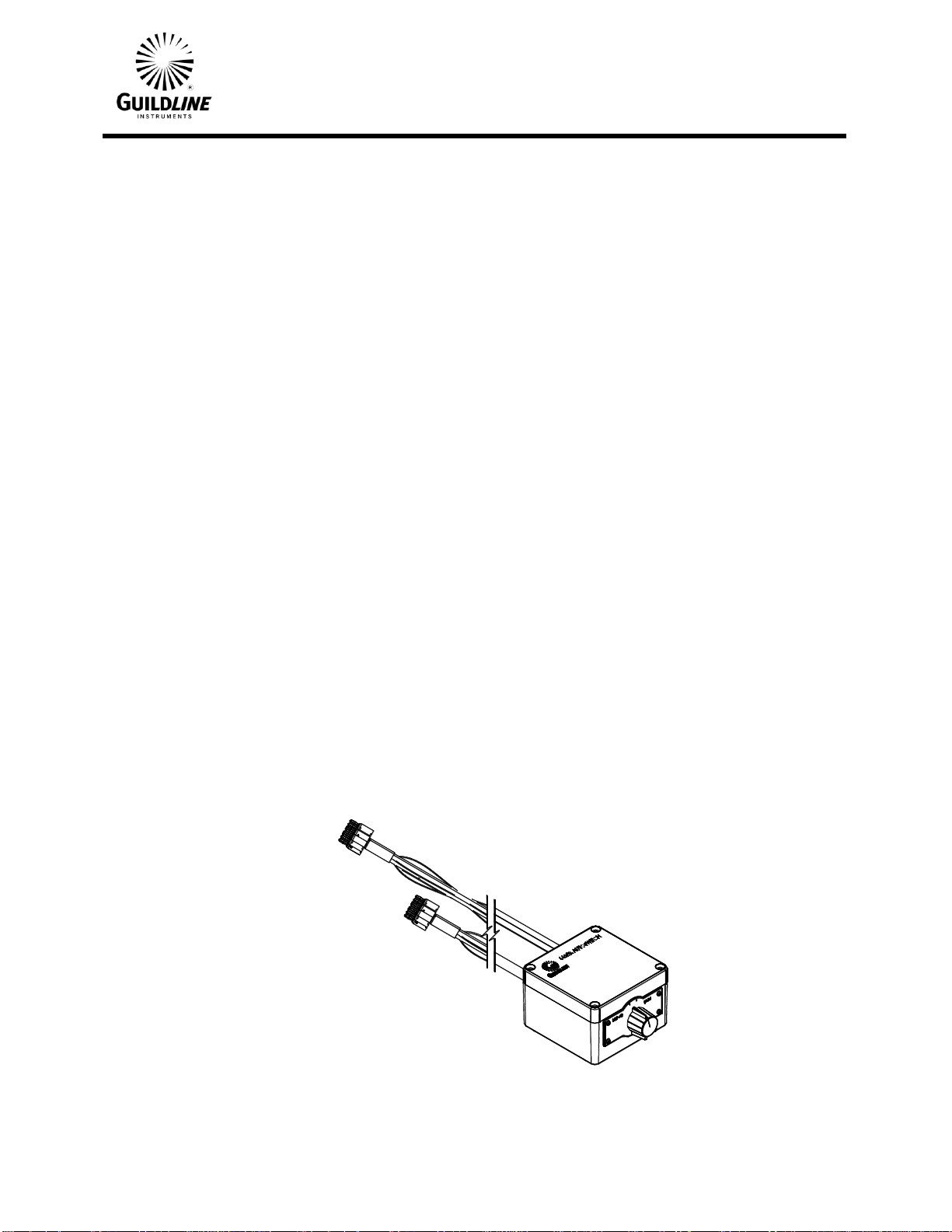
Model 66252A-R Autoswitch
Screwdriver, slotted
(Optional) Jumper for 2 Scanners
(Empty 3U location in 6625A System required)
2.2.2 Procedure
h) Power down the cabinet and disconnect from power source
i) Remove SCW cables between the 6622A Bridge Rs & Rx terminals and the 6664C
scanner output terminals and discard or retain for future use. (The Autoswitch cables
replace these.)
j) Remove 3U blank panel from front of 6625A cabinet, retain screws and washers for
installation of 66252A-R.
k) Install 66252A-R assembly into 3U hole with screws & washers from 3U blanking panel.
l) Install Autoswitch Cables to the 6664C scanner channel A and channel B output
terminals. Each cable end is labeled to indicate where it is to be connected.
m) Install Autoswitch Cables to the 6622A bridge Rs and Rx terminals. Each cable end is
labeled to indicate where it is to be connected.
n) Connect the green wire for Channel A and Channel B cable shields to the guard buss bar
on the left side of the cabinet.
o) Connect the green wire for Rs and Rx (C1P1& C2P21) cable shields to the 6622A guard
terminal.
p) Plug Cabinet power back into the power source.
Note: If there are two scanners install the optional jumper for the second scanner between
the Rx/Rs of the first scanner and the Rx/Rs of the second scanner.