Installation
7
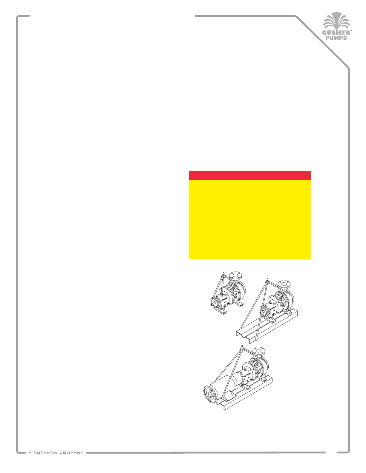
SYSTEM PIPING
Never force piping into position by
pulling it place with the pump suction
and discharge ange bolts.
This will cause misalignment between
pump and driver which will adversely
aect the operation of the unit,
resulting in physical injury and
damage to the equipment.
! WARNING !
NPSH must always exceed NPSH as
shown on Gusher performance curves.
Reference Hydraulic Institute for NPSH
and pipe friction values needed to
evaluate suction piping.
! WARNING !
Properly installed suction piping is
necessary for trouble-free pump
operation. Flush suction piping before
connection to the pump.
1). Never place a pipe line elbow in the
horizontal plane directly at the pump
suction. Use a straight pipe four to six
pipe diameters long between the elbow
and the pump suction.
2). Use suction pipe one or two sizes
larger than the pump suction, with an
eccentric reducer, sloping slide down,
at the suction ange. Suction piping
should never be smaller than the
pump suction.
3). Never throttle the pump on the suction
side. Always control ow by throttling
on the discharge side of the pump.
1). All piping must be supported independently
of the pump.
2). Before connecting the piping to the pump,
ensure that the base is secured.
3). Clean all pipe parts prior to installation.
Guidelines for piping are given in the
“Hydraulic Institute Standards” available
from the Hydraulic Institute, 30200 Detroit
Road, Cleveland, OH 44145-1967.
These guidelines should be followed
to ensure proper pump operation.
Suction Piping
4). Liquid coming back into the resevoir
should not enter near the pump suction
pipe and the liquid should not drop
from a high level.
5). An isolation valve should be installed in
the suction pipe at least 4 pipe diameters
from the suction to allow closing of the
line for pump inspection and
maintenance.
6). Pipe should be free of air pockets.
7). Piping should be level or slope
gradually downward from the source.
8). No part of the piping should extend
below pump suction ange.
9). The size of the entrance from the
supply should be one or two sizes
larger than the pipe.
1). A gate valve and check valve should
be installed in the discharge line. The
check valve should be installed
between the gate valve and the pump.
This will allow for inspection of
the check valve. The gate valve is
required for priming, ow regulation
and for maintenance of the pump.
The check valve is required to prevent
pump or seal damage from reverse ow
through the pump when the motor is
turned o.
2). If quick closing valves are installed in
the system, cushioning devices should
also be installed to protect the pump
from surges and water hammer.
3). A pressure gauge should be installed
in the piping just above the pump
discharge. This gauge should be located
at the pump discharge and before
any valves, elbows or other devices.
After all piping connections have been
made to the pump:
1) Rotate the shaft by hand to insure that
there is no binding and all parts are
free.
2) Re-check pump alignment to detect any
pipe strain. If pipe strain exists, correct
piping.
Discharge Piping
Final Piping Check
A R