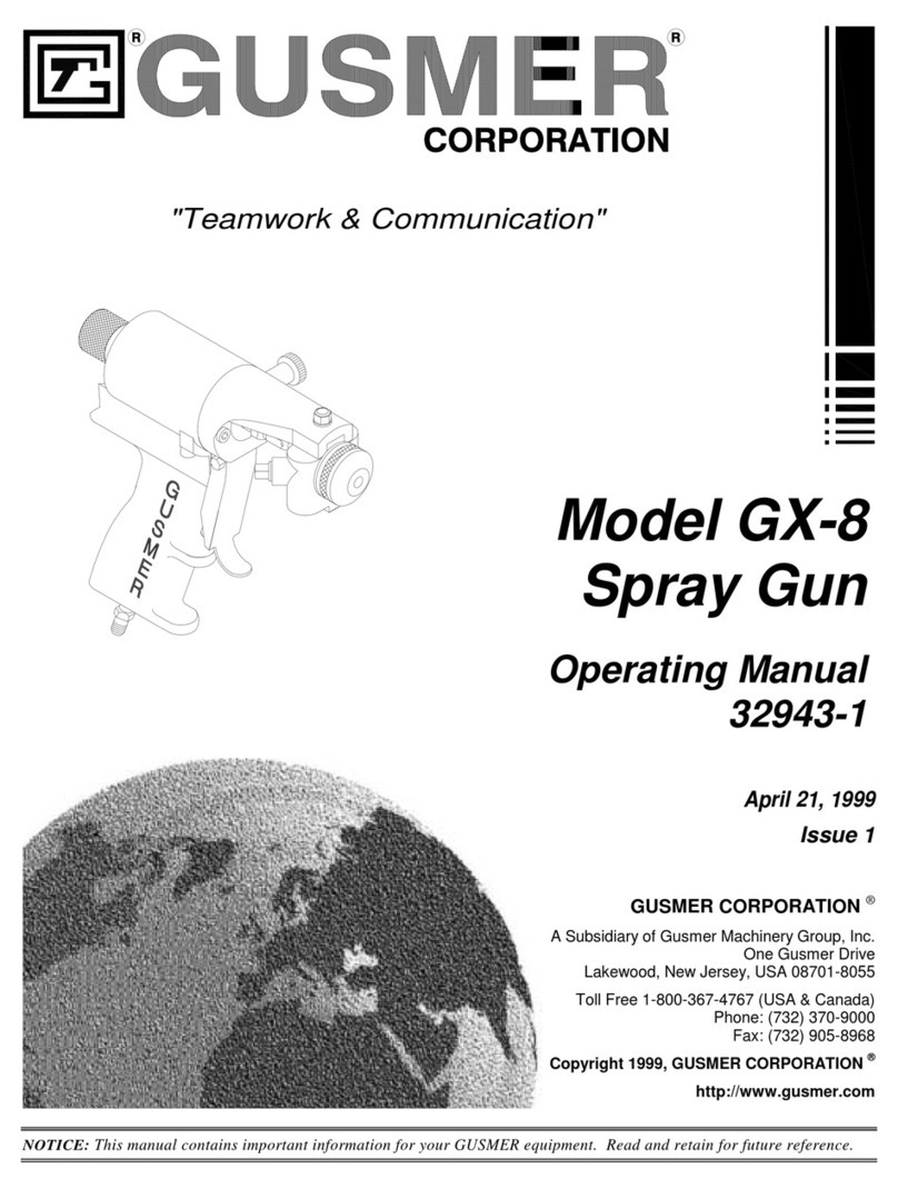
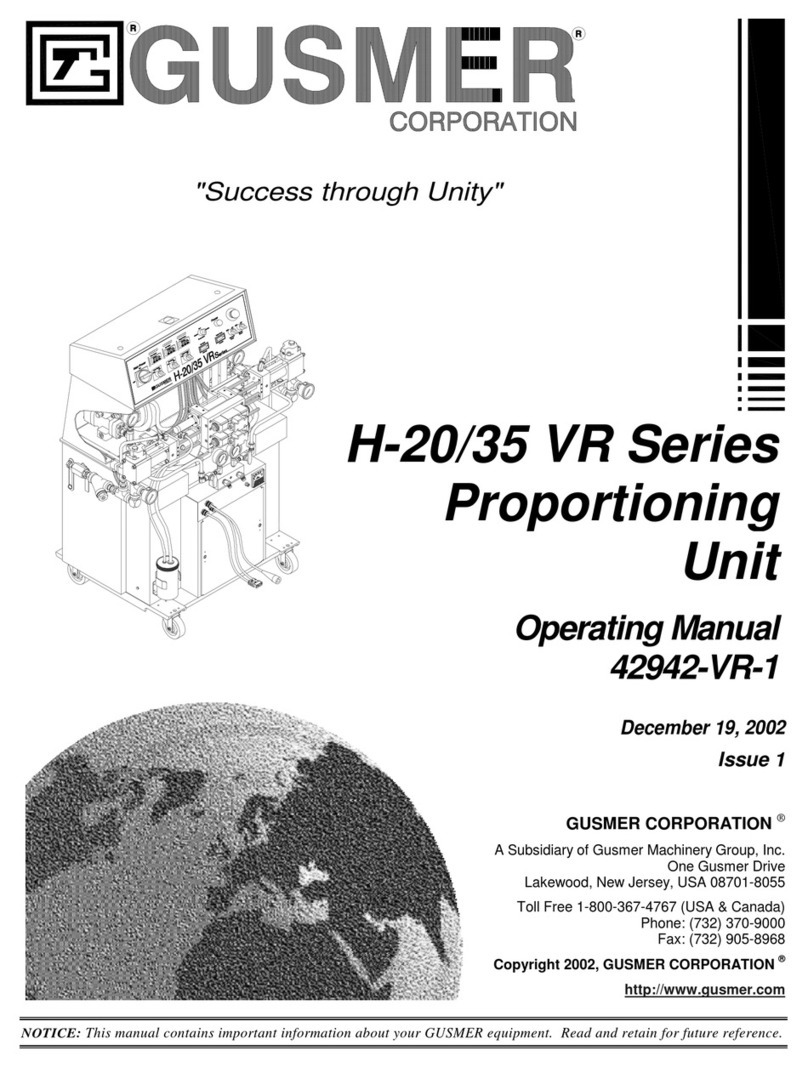
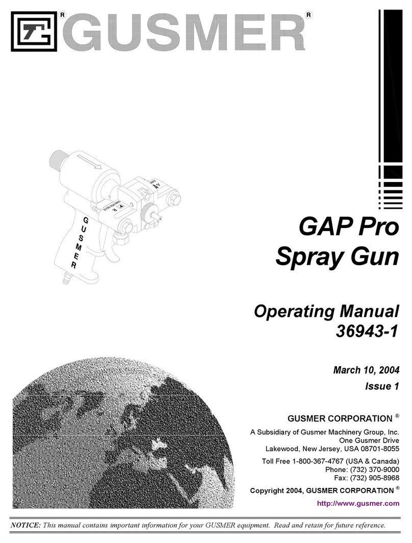
GUSMER GX-14 User manual

"Teamwork & Communication"
Model GX-14
Pour Head
Operating Manual
33943-1
January 19, 1999
Issue 2
GUSMER CORPORATION ®
A Subsidiary of Gusmer Machinery Group, Inc.
One Gusmer Drive
Lakewood, New Jersey, USA 08701-8055
Toll Free 1-800-367-4767 (USA & Canada)
Phone: (732) 370-9000
Fax: (732) 905-8968
Copyright 1999, GUSMER CORPORATION ®
http://www.gusmer.com
NOTICE: This manual contains important information for your GUSMER equipment. Read and retain for future reference.

Model GX-14 Pour Head
233943-1, Issue 2
CONTENTS
WARRANTY...............................................................................................................4
GENERAL SAFETY INFORMATION.....................................................................5
ACCEPTABLE EQUIPMENT USES...................................................................................5
OPERATIONAL SAFETY PROCEDURES...........................................................................6
DESCRIPTION...........................................................................................................7
GENERAL DESCRIPTION ..............................................................................................7
SPECIFICATIONS .........................................................................................................9
GX-14 TOOL KIT..................................................................................................... 10
PREPARATION FOR USE...................................................................................... 11
INITIAL SETUP PROCEDURE....................................................................................... 11
Procedure............................................................................................................ 12
OPERATION ............................................................................................................13
DAILY STARTUP PROCEDURES................................................................................... 13
DAILY SHUTDOWN PROCEDURES............................................................................... 13
MAINTENANCE...................................................................................................... 14
MAINTENANCE PROCEDURES .................................................................................... 14
Removing Mixing Chamber ................................................................................. 14
Installing New Mixing Chamber .......................................................................... 14
Installing Used Mixing Chamber......................................................................... 14
Cleaning Mixing Chamber................................................................................... 14
Servicing Hydraulic Cylinder.............................................................................. 16
INSTRUCTION MANUAL DISCREPANCY REPORT.........................................17

Operating Manual Contents
1/19/99 3
LIST OF FIGURES
FIGURE 1. MODEL GX-14 POUR GUN COMPONENTS .........................................................7
FIGURE 2. GX-14 MIXING CHAMBER W/ CHECK VALVES...................................................8
FIGURE 3. TOOL KIT (P/N 33980).................................................................................10
FIGURE 4. HOOK-UP DIAGRAM......................................................................................11
FIGURE 5. MODEL GX-14 HYDRAULIC CYLINDER ...........................................................16

Model GX-14 Pour Head
433943-1, Issue 2
WARRANTY
Gusmer Corporation (Gusmer) provides a limited warranty to the original purchaser (Customer) of
Gusmer manufactured parts and equipment (Product) against any defects in material or
workmanship for a period of one year from the date of shipment from Gusmer facilities.
In the event Product is suspected to be defective in material or workmanship, it must be returned to
Gusmer, freight prepaid. If Product is found to be defective in material or workmanship, as
determined solely by Gusmer, Gusmer will issue full credit to Customer for the freight charges
incurred in returning the defective Product, and either credit will be issued for the replacement cost
of the Product or a replacement part will be forwarded no-charge, freight prepaid to Customer.
This warranty shall not apply to Product Gusmer finds to be defective resulting from: installation,
use, maintenance, or procedures not accomplished in accordance with our instructions; normal
wear; accident; negligence; alterations not authorized in writing by Gusmer; use of “look alike”
parts not manufactured or supplied by Gusmer; or Product used in conjunction with any other
manufacturer's pumping or proportioning equipment. Further, the terms and conditions of this
warranty shall not apply to services or repairs made to Product by any third party not authorized in
writing by Gusmer. For such Product, a written estimate will be submitted to Customer at a
nominal service charge, itemizing the cost for repair. Disposition of Product will be done in
accordance with the terms stated on the written estimate.
The warranty provisions applied to product that are not manufactured by Gusmer will be solely in
accordance with the warranty provided by the original manufacturer of the product.
GUSMER MAKES NO WARRANTY WHATSOEVER AS TO THE MERCHANTABILITY OF,
OR SUITABILITY FOR, ITS PRODUCT TO PERFORM ANY PARTICULAR PURPOSE.
CREDIT FOR, OR REPLACEMENT OF, PRODUCT DEFECTIVE IN MATERIAL OR
WORKMANSHIP SHALL CONSTITUTE COMPLETE FULFILLMENT OF GUSMER
OBLIGATIONS TO CUSTOMER. NO OTHER WARRANTY, EXPRESSED OR IMPLIED ON
ANY PRODUCT IT MANUFACTURES AND/OR SELLS, WILL BE RECOGNIZED BY
GUSMER UNLESS SAID WARRANTY IS IN WRITING AND APPROVED BY AN OFFICER
OF GUSMER.
Under no circumstances shall Gusmer be liable for loss of prospective or speculative profits, or
special indirect, incidental or consequential damages. Further, Gusmer shall have no liability for
any expenses including, but not limited to personal injury or property damage resulting from failure
of performance of the product, use of the product, or application of the material dispensed through
the product. Any information provided by Gusmer that is based on data received from a third
source, or that pertains to product not manufactured by Gusmer, while believed to be accurate and
reliable, is presented without guarantee, warranty, or responsibility of any kind, expressed or
implied.
Gusmer through the sale, lease, or rental of Product in no way expresses or implies a license for the
use of, nor encourages the infringement of any patents or licenses.
To insure proper validation of your warranty, please complete the warranty card and return it to
Gusmer within two weeks of receipt of equipment.
Revised 11/12/98

Operating Manual General Safety Information
1/19/99 5
GENERAL SAFETY INFORMATION
It is necessary to understand and follow the instructions in this manual to insure proper
and safe operation of the equipment.
As with most mechanical equipment, certain safety precautions must be taken when the
equipment discussed in this manual is operated or serviced. Severe bodily injury or
damage to equipment and property may result if the instructions and precautions listed
throughout this manual are not followed.
Needless to say, sufficient guidelines cannot be developed to eliminate the need for good
common sense in the use and servicing of this equipment, and in the use and application
of the products, this equipment has been designed to process. Users of this equipment
must therefore, make their own determination as to the suitability of the information
contained in this manual to their specific operation and requirements. There should be
no assumption made that the safety measures and instructions contained herein are all-
inclusive, and that other safety measures may not be required for specific use or
application.
The following safety guidelines are generally applicable to the safe and efficient use of
the equipment.
Acceptable Equipment Uses
The equipment is designed for the dispensing of polyurethane foams, two-component
coating systems, and some two-component epoxy systems, specifically polyureas. Under
no circumstances should any acid or corrosive chemicals be used in the unit. Consult
GUSMER if there is any doubt about the compatibility of the chemical system to be used
in this equipment.
Any use of this equipment other than as indicated above constitutes misuse unless
express written approval is obtained from GUSMER.

Model GX-14 Pour Head
633943-1, Issue 2
Operational Safety Procedures
This safety information will not be repeated in the text of this manual. The symbols
pertaining to this information will appear where appropriate to alert the operator to
potential hazards.
Solvents and Chemicals
WARNING:THE SOVENTS AND CHEMICAL USED WITH THIS EQUIPMENT EXPOSE THE
OPERATOR TO CERTAIN HAZARDS. ADEQUATE PERSONAL PROTECTIVE MEASURES MUST BETAKEN
SO AS TO AVOID EXCEEDING THE THRESHOLD LIMIT VALUE (TLV) OF THE PRODUCTS BEING
USED, AS ESTABLISHED BY THE OCCUPATIONAL SAFETY AND HEALTH ADMINISTRATION (OSHA)
OR OTHER QUALIFIED AGENCY. INFORMATION CONCERNING PERSONAL PROTECTION AND
PROPER HANDLING FROM THE SUPPLIER OF SUCH CHEMICALS.
High Voltage
WARNING:TO PREVENT SERIOUS BODILY INJURY FROM ELECTRICAL SHOCK, NEVER OPEN THE
ELECTRIC CONSOLES OR OTHERWISE SERVICE THIS EQUIPMENT AND/OR EQUIPMENT USED WITH
IT BEFORE SWITCHING OFF THE MAIN POWER DISCONNECT AND INTERRUPTING SUPPLY VOLTAGE
AT THE SOURCE. THE ELECTRICAL SERVICE MUST BE INSTALLED AND MAINTAINED BY A
QUALIFIED ELECTRICIAN.
High Pressure
WARNING:THIS EQUIPMENT HAS OR IS USED WITH EQUIPMENT THAT HAS HYDRAULIC
COMPONENTS CAPABLE OF PRODUCING UP TO 3500 PSI. TO AVOID SERIOUS BODILY INJURY
FROM HYDRAULIC INJECTION OF FLUID, NEVER OPEN ANY HYDRAULIC CONNECTIONS OR SERVICE
HYDRAULIC COMPONENTS WITHOUT BLEEDING ALL PRESSURES TO ZERO.
Personal Protective
Equipment
WARNING:TO AVOID SERIOUS BODILY INJURY, PROPER PROTECTIVE GEAR MUST BE WORN
WHEN OPERATING, SERVICING, OR BEING PRESENT IN THE OPERATIONAL ZONE OF THIS
EQUIPMENT. THIS INCLUDES, BUT IS NOT LIMITED TO, EYE AND FACE PROTECTION, GLOVES,
SAFETY SHOES, AND RESPIRATORY EQUIPMENT AS REQUIRED.
High Temperature
WARNING:THIS EQUIPMENT HAS OR IS USED WITH EQUIPMENT THAT HAS HIGH
TEMPERATURE COMPONENTS SUCH AS PRIMARY HEATERS AND HEATED HOSES. TO PREVENT
SERIOUS BODILY INJURY FROM HOT FLUID OR HOT METAL, NEVER ATTEMPT TO SERVICE THE
EQUIPMENT BEFORE ALLOWING IT TO COOL.
Warning
WARNING: FAILURE TO READ AND FOLLOW THIS SAFETY INFORMATION MAY RESULT IN
PERSONAL INJURY AND/OR DAMAGE TO THE EQUIPMENT FROM ONE OR MORE OF THE ABOVE
LISTED HAZARDS

Operating Manual Description
1/19/99 7
DESCRIPTION
General Description
The design of the Gusmer GX-14 Pour Gun represents a milestone in engineering
design which is so unique that the GX-14 will stand alone as it sets the standard by
which all other guns are measured.
The GX-14 was designed for the automotive industry to provide them with a gun
offering the following features:
•Easy to operate and maintain
•Light weight
•Ergonomically balanced
•Hydraulically actuated
•Non-adjustable
•Rebuildable
Before proceeding with the following procedures, familiarize yourself with the parts of
the GX-14 Gun (Figure 1), so that you may relate to them as you read this manual.
Figure 1. Model GX-14 pour Gun Components
1. Mixing Chamber
2. Hydraulic Cylinder
3. Pistol Grip
4. Pour Handle
5. Proximity Switch
6. Trigger Switch Connector
7. Spacer Covers
8. Coupling Block

Model GX-14 Pour Head
833943-1, Issue 2
Although new and unique in many aspects, the mixing chamber utilizes direct
impingement mixing while the 1/4” valving rod allows for many hours of self-cleaning
use. The GX-14 Mixing Chamber provides the following features:
•Self-cleaning
•Direct impingement
•Various nozzles to choose from dependent on application
•Specific orifice sizes can be specified
•Rebuildable
•Warranted for 50,000 shots (based on 2 seconds between shots)
•No adjustments required
Before proceeding with the following procedures, familiarize yourself with the parts of
the GX-14 Mixing Chamber Assembly (Figure 2), so that you may relate to them as you
read this manual.
Figure 2. GX-14 Mixing Chamber W/ Check Valves
1. Chamber
2. Nozzle
3. Check Valves
4. Retainer Nut
5. Valving Rod
WARNING: REMOVING NOZZLE FROM CHAMBER WILL VOID WARRANTY.

Operating Manual Description
1/19/99 9
Specifications
US Metric
Maximum Output: 40 lbs/min 18 kg/min
Minimum Output 3.50 lbs/min 2 kg/min
Max. Operating Pressure: 3500 psi 241 bar
Hydraulic Supply 1800-2500 psi 124-172 bar
Mixing Internal Impingement, Mechanically Self-Cleaning
Weight: less than 3.5 lbs 1.5 kg
Dimensions: H=8", W=11", D=3" H=20, L=28, D=8cm

Model GX-14 Pour Head
10 33943-1, Issue 2
GX-14 Tool Kit
The following tools (Figure 3) are supplied with the GX-14 Tool Kit
Figure 3. GX-14 Tool Kit (P/N 33980)
1. 3/16 Hex Key Wrench
2. 5/32 Hex Key W/ Ball End
3. 9/64 Hex Key Wrench
4. 3/32 Hex Key Wrench
5. Utility Knife
6. Pin Vise
7. Gasket Removal Tool
8. Flush can
9. 10” Adjustable Wrench
10. 6” Adjustable Wrench
11. 1/2” Comb Wrench-Mod
12. 10mm Wrench
13. 7/16” Wrench-Mod
14. #W Flat Bottom Drill
15. # I Drill
16. 3/16 Drill
17. 5/32 Drill
18. 1/8 Drill
19. #61 Drill
20. 5/16 Nut Driver

Operating Manual Preparation For Use
1/19/99 11
PREPARATION FOR USE
Initial Setup Procedure
The following diagram is for reference only. Each application could vary. Refer to GX-
14 Hydraulic Power Pack Operator’s Manual for further information.
Figure 4. Hook-up Diagram
1. Directional Control Valve
2. Accumulator
3. Accumulator Charging Valve
4. Hydraulic Hoses (P/N 19200-25) working pressure < 2500 psi
5. Trigger Switch Cable (P/N 33161) - controls directional control valve
6. Proximity Switch Cable (P/N 33160) - allows capability of dispensing timed shots
7. TX-50 Timer Harness (P/N 33163)
8. Control Cable (7’)(FF-1600 – P/N OP305-11000)
(H-2000 – P/N OP305-1000)
9. Extension Harness (10’-25’-50’)(P/N OP5172A-8-Size)
10. Encoder Cable (7’)(P/N OP321)
11. Encoder Extension (25’-50’)(P/N OP304-10-Size)

Model GX-14 Pour Head
12 33943-1, Issue 2
PROCEDURE
1. Verify GX-14 Hydraulic Power Pack or equivalent is off.
2. Install hydraulic hose to the power pack. Hoses should be 1/4” ID rated for ≥2500
psi working pressure and greater than 15’ in length.
3. Connect end of hoses together utilizing a 7/16” JIC male / 7/16” JIC male adapter
at gun end.
4. Turn on power pack. Pressure should not increase while air is purged from
hydraulic hoses.
5. Turn power pack off. Verify that no pressure exists.
6. Remove hydraulic adapter utilized in step 3 and attach hoses to GX-14 gun as
indicated on diagram.
7. Set power pack in manual mode.
8. Attach proximity switch cable and trigger switch cable to GX-14 gun and GX-14
Power Pack.
NOTE:
A two second delay between
triggering of gun is required to
ensure life of mixing chamber. 9. With chemical hoses unattached, trigger GX-14 “only” two or three times. This
will purge the air that was remaining in gun.
10. Verify GX-14 Hydraulic Power Pack pressure is between 1800 and 2500 psi.
Adjust power pack if required.
NOTE:
If during normal operation the
valving rod does not retract in
mixing chamber and the hydraulic
pressure is 2500 psi, contact
technical service department.
11. Install chemical hoses / coupling block

Operating Manual Operation
1/19/99 13
OPERATION
Daily Startup Procedures
1. Remove spacer covers and remove any debris behind mixing chamber.
2. Verify that retainer nut is securely fastened to piston of hydraulic cylinder.
3. Replace spacer covers.
4. Verify proximity cable and trigger cable are connected on machine and gun
correctly w/o frayed cable.
5. Close dump valve on GX-14 Hydraulic Power Pack or equivalent.
6. Start power pack and verify maximum pressure to be between 1800 and 2500 psi
(NOTE: hydraulic pressure to GX-14 Gun should not exceed 2500 psi).
7. Start processing equipment (i.e. H2000) and allow unit to warm up.
8. Open coupling block
9. Dispense shot in appropriate container while verifying chemical pressures (NOTE:
if processing pressures are not correct, refer to Servicing Procedures to clean mixing
chamber).
10. Wipe any residual dispensed material from tip of mixing chamber.
Daily Shutdown Procedures
1. Close valves on coupling block.
2. Turn off GX-14 Hydraulic Power Pack.
3. Bleed hydraulic pressure via dump valve on Power Pack.
4. Turn off processing equipment.
5. Remove any residual dispensed material from mixing chamber

Model GX-14 Pour Head
14 33943-1, Issue 2
MAINTENANCE
Maintenance Procedures
REMOVING MIXING CHAMBER
1. Close manual valves on coupling block (5/16” spintite).
2. Bleed hydraulic pressure from GX-14 gun.
3. Remove coupling block (5/16” spintite).
4. Remove check valves (gasket removal tool) and rinse with approved solvent. Keep
track of which chemical each was removed from.
5. Remove both spacer covers (7/64” Hex-key).
6. Remove socket head cap screws (2) from front of mixing chamber and remove
chamber (3/16” Hex-key).
7. Remove retainer nut from piston rod (1/2” & 7/16” wrench-modified).
INSTALLING NEW MIXING CHAMBER
1. Place retainer nut on valving rod and secure to piston. Valving rod should not be
rigidly attached to piston (1/2” & 7/16” wrench-modified) Take care not to get
anything on valving rod.
2. Place spacer and mixing chamber on valving rod and secure to front spacer with
hardware. (3/16” Hex-key).
NOTE:
The mixing chamber can be rotated
180oif required for specific
applications 3. Replace spacer covers (7/64” Hex-key).
INSTALLING USED MIXING CHAMBER
1. Place spacer onto front spacer prior to threading retainer nut to piston. The valving
rod, retainer nut and mixing chamber will be assembled together do to prior use
(1/2” & 7/16” wrench-modified).
2. Secure mixing chamber to front spacer with hardware. (3/16” Hex-key).
NOTE:
The mixing chamber can be rotated
180oif required for specific
applications 3. Replace spacer covers (7/64” Hex-key).
CLEANING MIXING CHAMBER
Clean Orifices
1. Close manual valves on coupling block (5/16” spintite).
2. Set power pack to manual mode. (Manual mode will allow the operator to retract
the valving rod as long as the trigger is depressed).

Operating Manual Maintenance
1/19/99 15
3. Remove the hex head plug on the side of the chamber that has unbalanced (higher)
pressure. (7/16” wrench).
4. Flush mixing chamber cavity with approved solvent.
5. Remove any debris in cavity.
6. Depress trigger and hold. Utilizing pin vise and appropriate drill bit (drill bit
should match orifice size) clean orifice. Flush with approved solvent. Release
trigger. Repeat.
7. Replace hex head plug.
8. Open manual valves on coupling block.
9. Dispense shot in appropriate container and verify proper pressure.
10. If pressures are not balanced remove and replace (clean) check valves in mixing
chamber.
Clean Check Valves
1. Close manual valves on coupling block (5/16” spintite).
2. Remove coupling block (5/16” spintite).
3. Remove check valves and clean(gasket removal tool).
4. Remove the hex head plugs on the side of the chamber (7/16” wrench).
5. Utilizing appropriate drill bit, clean cavity. Flush with approved solvent.(“U” drill,
5/32” drill).
6. Replace hex head plug.
7. After cleaning or replacing with new, install check valves. Verify check valves are
able to be depressed.
8. Attach coupling block.
9. Open manual valves on coupling block.
10. Dispense shot in appropriate container and verify proper pressure.
Cleaning Front Spacer
Important: During normal use, debris will build-up behind the mixing chamber.
This debris must be removed on a daily bases so that it does not prevent proper
operation.
1. Close manual valves on coupling block (5/16” spintite).
2. Remove both spacer covers (7/64” Hex-key).
3. Remove debris.
4. Replace spacer covers.

Model GX-14 Pour Head
16 33943-1, Issue 2
SERVICING HYDRAULIC CYLINDER
Figure 5. Model GX-14 Hydraulic Cylinder
Replacing O-rings in Hydraulic cylinder
(Refer to Parts ID 33943-ID)
NOTE:
all o-rings/seals that utilized in
hydraulic cylinder are found in
33121-500-pkg 1. Bleed hydraulic pressure from GX-14 gun.
2. Disconnect proximity switch cable and trigger cable.
3. Remove mixing chamber (refer to page 9).
4. Remove front spacer (3/16” hex-key).
5. Remove pistol grip/vertical handle assembly (5/32” hex-key).
6. Remove saddle handle mount (5/32” hex-key).
7. Remove extended fitting (wrench).
8. Remove proximity switch (10mm Wrench).
9. Remove end cap of cylinder (9/64” hex-key).
10. Remove piston carefully.
11. Replace o-rings/u-cup. Take care to install u-cups in same manner as removed and
do not damage while installing.
12. Reassemble in reverse order-take care not to pinch or damage
O-ring/U-cups.

Operating Manual Instruction Manual Discrepancy Report
1/19/99 17
INSTRUCTION MANUAL DISCREPANCY REPORT
Field
Number Field Title Description
1Date
2Name
3IM Number
4Issue Number
5Date of Issue
6Page Number
7Discrepancy
Instructions:
Complete the above fields of the form by following the instructions listed on the reverse side of this sheet and mail to:
Gusmer Corporation
One Gusmer Drive PO Box 2055
Lakewood, NJ 08701

Model GX-14 Pour Head
18 33943-1, Issue 2
Field
Number Field Title Description
1Date Enter date report is submitted.
2Name Enter name of person making report.
3IM Number Enter the Part Number of the Instruction Manual from the title page.
4Issue Number Enter the Issue number of the Instruction Manual from the title page. If there is no
issue number, enter NONE.
5Date of Issue Enter the date of Issue of the Instruction Manual from the title page. If there is no
issue date, enter NONE.
6Page Number Enter the page number containing the discrepancy
7Discrepancy Provide a brief description of discrepancy
NOTE: You may send a marked copy of the page as an attachment to your
submittal.
Table of contents
Other GUSMER Paint Sprayer manuals