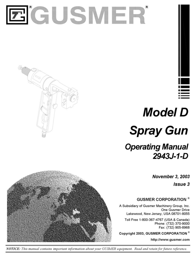
GUSMER D User manual

"Teamwork & Communication"
Model D
Spray Gun
Operating Manual
2943J-1-D
May 5, 1997
Issue 2
GUSMER CORPORATION ®
A Subsidiary of Gusmer Machinery Group, Inc.
One Gusmer Drive
Lakewood, New Jersey, USA 08701-8055
Toll Free 1-800-367-4767 (USA & Canada)
Phone: (732) 370-9000
Fax: (732) 905-8968
Copyright 1999, GUSMER CORPORATION ®
http://www.gusmer.com
NOTICE: This manual contains important information for your GUSMER equipment. Read and retain for future reference.

GUSMER Model D Spray Gun
22943J-1-ID Issue 2
CONTENTS
WARRANTY...............................................................................................................4
GENERAL SAFETY INFORMATION.....................................................................5
ACCEPTABLE EQUIPMENT USES............................................................................5
SOLVENTS AND CHEMICALS..................................................................................6
HIGH VOLTAGE.........................................................................................................6
HIGH PRESSURE.........................................................................................................6
PERSONAL PROTECTION .........................................................................................6
HIGH TEMPERATURE................................................................................................6
OPERATIONAL SAFETY PROCEDURES-WARNINGS.............................................7
DESCRIPTION...........................................................................................................8
GENERAL DESCRIPTION.......................................................................................... 8
SPECIFICATIONS.......................................................................................................9
EQUIPMENT SUPPLIED........................................................................................... 10
OPERATION ............................................................................................................11
DAILY STARTUP PROCEDURES ............................................................................ 11
DAILY SHUTDOWN PROCEDURES........................................................................ 15
MAINTENANCE...................................................................................................... 18
MAINTENANCE PROCEDURES.............................................................................. 18
Cleaning Injection Slots.............................................................................................. 18
Gun Screen Maintenance ............................................................................................ 20
Expanded Disassembly and Cleaning Procedures ....................................................... 21
Expanded Assembly Procedures.................................................................................. 25
TROUBLESHOOTING............................................................................................28
INTRODUCTION....................................................................................................... 28
TROUBLESHOOTING PROCEDURES ..................................................................... 29
Valving Rod Does Not Open........................................................................................ 29
Liquid Does Not Enter The Mixing Chamber............................................................... 29
Poor Pattern Development.......................................................................................... 30
Leakage ...................................................................................................................... 30
APPENDIX................................................................................................................ 32
APPENDIX A............................................................................................................. 32
Chamber Description Chart........................................................................................ 32
APPENDIX B............................................................................................................. 33
Table 1. Chamber Operating Chart for Adjustment of the Valving Rod ...................... 33
APPENDIX C............................................................................................................. 34
Abbreviated Procedures.............................................................................................. 34
Abbreviated Start-up Procedures ................................................................................ 34
Abbreviated Shut-down Procedures............................................................................. 34

Operating Manual Contents
5/5/97 3
LIST OF FIGURES
FIGURE 1. MODEL D SPRAY GUN COMPONENTS..................................................................... 8
FIGURE 2. TOOL KIT ............................................................................................................ 10
FIGURE 3. VALVING ROD (CLOSED POSITION)....................................................................... 11
FIGURE 4. VALVING ROD (OPEN POSITION)........................................................................... 11
FIGURE 5. FRICTION LOCK ................................................................................................... 11
FIGURE 6. AIR NEEDLE VALVE ............................................................................................. 11
FIGURE 7. FELT WIPER (ADJUSTMENT)................................................................................. 12
FIGURE 8. FELT WIPER (SERVICE)......................................................................................... 12
FIGURE 9. POINT OF VALVING .............................................................................................. 13
FIGURE 10. OPENING THE PATTERN...................................................................................... 13
FIGURE 11. DESIRED PATTERN ............................................................................................. 14
FIGURE 12. SPLIT PATTERN.................................................................................................. 14
FIGURE 13. MANUAL VALVES............................................................................................... 18
FIGURE 14. CHECK VALVES.................................................................................................. 18
FIGURE 15. CLEANOUT PORTS.............................................................................................. 19
FIGURE 16. VALVING ROD AND ADJUSTMENT SCREW............................................................ 19
FIGURE 17. CLEANOUT PORTS.............................................................................................. 19
FIGURE 18. SCREEN SCREW ASSY MOUNTING SCREW............................................................ 20
FIGURE 19. AIR CAP ............................................................................................................ 21
FIGURE 20. VALVING ROD REMOVAL.................................................................................... 21
FIGURE 21. VALVING ROD.................................................................................................... 22
FIGURE 22. COUPLING BLOCK MOUNTING SCREW................................................................. 22
FIGURE 23. GUN BLOCK MOUNTING SCREW.......................................................................... 22
FIGURE 24. MIXING CHAMBER REMOVAL.............................................................................. 23
FIGURE 25. CHECK VALVE ................................................................................................... 23
FIGURE 26. SLEEVE REMOVAL BLOCK................................................................................... 24
FIGURE 27. MIXING CHAMBER ............................................................................................. 25
FIGURE 28. MIXING CHAMBER LOCATION............................................................................. 25
FIGURE 29. MIXING CHAMBER INSERTION ............................................................................ 26
FIGURE 30. VALVING ROD POSITIONER................................................................................. 26
FIGURE 31. LEAKAGE AREAS................................................................................................ 31
LIST OF TABLES
TABLE 1. CHAMBER OPERATING CHART FOR ADJUSTMENT OF THE VALVING ROD ................. 33

GUSMER Model D Spray Gun
42943J-1-ID Issue 2
WARRANTY
GUSMER provides a limited warranty to the original purchaser (Customer) of GUSMER
manufactured parts and equipment (Product) against any defects in material or workmanship for a
period of one year from the date of shipment from GUSMER facilities.
In the event Product is suspected to be defective in material or workmanship, it must be returned
to GUSMER, freight prepaid. If Product is found to be defective in material or workmanship, as
determined solely by GUSMER, GUSMER will issue full credit to Customer for the freight
charges incurred in returning the defective Product, and either credit will be issued for the
replacement cost of the Product or a replacement part will be forwarded no-charge, freight prepaid
to Customer.
This warranty shall not apply to Product GUSMER finds to be defective resulting from:
installation, use, maintenance, or procedures not accomplished in accordance with our
instructions; normal wear; accident; negligence; alterations not authorized in writing by
GUSMER; or Product use in conjunction with any other manufacturer's pumping or proportioning
equipment. Further, the terms and conditions of this warranty shall not apply to services or
repairs made to Product by any third party not authorized in writing by GUSMER. For such
Product, a written estimate will be submitted to Customer, itemizing the cost for repair.
Disposition of Product will be done in accordance with the terms stated on the written estimate.
The warranty provisions applied to Product that are not manufactured by GUSMER will be solely
in accordance with the warranty provided by the original manufacturer of the Product.
GUSMER MAKES NO WARRANTY WHATSOEVER AS TO THE MERCHANTABILITY OF,
OR SUITABILITY FOR, ITS PRODUCT TO PERFORM ANY PARTICULAR PURPOSE.
CREDIT FOR, OR REPLACEMENT OF, PRODUCT DEFECTIVE IN MATERIAL OR
WORKMANSHIP SHALL CONSTITUTE COMPLETE FULFILLMENT OF GUSMER
OBLIGATIONS TO CUSTOMER. NO OTHER WARRANTY, EXPRESSED OR IMPLIED ON
ANY PRODUCT IT MANUFACTURES AND/OR SELLS, WILL BE RECOGNIZED BY
GUSMER UNLESS SAID WARRANTY IS IN WRITING AND APPROVED BY AN OFFICER
OF GUSMER.
Under no circumstances shall GUSMER be liable for loss of prospective or speculative profits, or
special indirect, incidental or consequential damages. Further, GUSMER shall have no liability
for any expenses including, but not limited to personal injury or property damage resulting from
failure of performance of the product, use of the product, or application of the material dispensed
through the product. Any information provided by GUSMER that is based on data received from
a third source, or that pertains to product not manufactured by GUSMER, while believed to be
accurate and reliable, is presented without guarantee, warranty, or responsibility of any kind,
expressed or implied..
GUSMER through the sale, lease, or rental of Product in no way expresses or implies a license for
the use of, nor encourages the infringement of any patents or licenses.

Operating Manual General Safety Information
5/5/97 5
GENERAL SAFETY INFORMATION
The instructions in this manual must be understood and followed to insure
proper and safe operation of the equipment.
As with most mechanical equipment, certain safety precautions must be
taken when the equipment discussed in this manual is operated or serviced.
If the instructions and precautions listed throughout this manual are not
followed, severe bodily injury or damage to equipment and property may
result.
Needless to say, sufficient guidelines cannot be developed to eliminate the
need for good common sense in the use and servicing of this equipment,
and in the use and application of the products this equipment has been
designed to process. Users of this equipment must therefore, make their
own determination as to the suitability of the information contained in this
manual to their specific operation and requirements. There should be no
assumption made that the safety measures and instructions contained herein
are all-inclusive, and that other safety measures may not be required for
specific use or application.
The following safety guidelines are generally applicable to the safe and
efficient use of the equipment.
ACCEPTABLE EQUIPMENT USES
The equipment is designed for the proportioning and dispensing of two-
component urethane foam, or coating systems and some two-component
epoxy systems. Under no circumstances should any acid or corrosive
chemicals be used in the unit. Consult GUSMER if there is any doubt about
the compatibility of the system to be used in this equipment.
The electrical circuitry of this equipment is not of explosion-proof design
and, therefore, the equipment must not be used in any environment
requiring this design.
Any use of this equipment other than as indicated above constitutes misuse
unless express written approval is obtained from GUSMER.

GUSMER Model D Spray Gun
62943J-1-ID Issue 2
SOLVENTS AND CHEMICALS
It is the users responsibility to insure that adequate personal protective
measures are taken so as not to exceed the Threshold Limit Value (TLV)
of the products being used, as established by the Occupational Safety and
Health Administration or other qualified agency. The user must be aware
of the exposure limits specified for the products being used, and must use
them in accordance with the recommendations specified by their
manufacturer.
HIGH VOLTAGE
The electrical service should be installed by a qualified electrician. Entry
into any of the electrical components should be made only by trained and
qualified personnel.
HIGH PRESSURE
The Power Pack system can develop pressures up to 3,000 pounds per
square inch. Anyone using a spray gun or mix head must use extreme
caution to insure the gun or head is never pointed at or near any persons,
and that the head is never actuated with the outlet tip blocked or restricted
by any part of the body.
PERSONAL PROTECTION
The use of solvents and chemicals will be required when operating,
servicing or cleaning. To prevent excessive exposure to the chemicals and
solvents to which will be used when operating this equipment, appropriate
personal protective gear such as eye and face protection, respiratory
protection, and protective gloves and clothing may be required.
HIGH TEMPERATURE
There are high temperature components, particularly the primary heater.
Before performing maintenance, allow the component to cool to avoid
bodily injury from hot fluid or hot metal.

Operating Manual General Safety Information
5/5/97 7
OPERATIONAL SAFETY PROCEDURES-WARNINGS
NOTE: These warnings will
not be repeated in the text of
this manual. The symbols
pertaining to these warnings
will appear where appropriate
to alert the operator to
potential hazards.
raw materials and solvents
WARNING: THE RAW MATERIALS AND SOLVENTS USED WITH THIS EQUIPMENT
EXPOSE THE OPERATOR TO CERTAIN HAZARDS. IN ORDER TO PREVENT BODILY INJURY,
INFORMATION CONCERNING PERSONAL PROTECTION AND PROPER HANDLING OF THESE
CHEMICALS MUST BE OBTAINED FROM THE SUPPLIER OF SUCH CHEMICALS.
electrical shock
WARNING: TO PREVENT SERIOUS BODILY INJURY FROM ELECTRICAL SHOCK, NEVER
OPEN THE ELECTRIC CONSOLES OR OTHERWISE SERVICE THE EQUIPMENT BEFORE
SWITCHING OFF THE MAIN POWER DISCONNECT AND INTERRUPTING SUPPLY VOLTAGE
AT THE SOURCE ELECTRICAL SERVICE MUST BE INSTALLED BY A QUALIFIED
ELECTRICIAN.
hydraulic PRESSURE
WARNING: THE HYDRAULIC COMPONENTS ARE PRESSURIZED UP TO 3000 PSI. TO
AVOID SERIOUS BODILY INJURY FROM HYDRAULIC INJECTION OF FLUID, NEVER OPEN
ANY HYDRAULIC CONNECTIONS OR SERVICE HYDRAULIC COMPONENTS BEFORE ALL
PRESSURES HAVE BEEN BLED TO ZERO.
proper protective gear
WARNING: TO AVOID SERIOUS BODILY INJURY, PROPER PROTECTIVE GEAR MUST BE
WORN WHEN OPERATING, SERVICING, OR BEING PRESENT IN THE OPERATIONAL ZONE
OF THIS EQUIPMENT. THIS INCLUDES, BUT IS NOT LIMITED TO, EYE PROTECTION,
GLOVES, SAFETY SHOES AND RESPIRATORY EQUIPMENT AS REQUIRED.
TEMPERATURE
WARNING: TO PREVENT SERIOUS BODILY INJURY FROM HOT FLUID OR HOT
METAL, NEVER ATTEMPT TO SERVICE THE EQUIPMENT BEFORE ALLOWING IT TO
COOL.

GUSMER Model D Spray Gun
82943J-1-ID Issue 2
DESCRIPTION
GENERAL DESCRIPTION
Figure 1. Model D Spray Gun Components
1. Valving Rod Adjustment Screw
2. Manual Valves
3. Friction Lock
4. Valving Rod Closure Spring
5. Valving Rod Stop Bar
6. Valving Rod Positioner
7. Gun Block Mounting Screw
8. Gun Block
9. Valving Rod
10. Trigger
11. Air Needle Valve
12. Screen Screw Assembly
13. Air Cap
14. Spring Retainer Case
15. Check Valves
16. Mixing Chamber
17. Felt Wiper

Operating Manual Description
5/5/97 9
SPECIFICATIONS
RECOMMENDED
USE: The equipment is designed for use with "standard" urethane foam spray
systems. Other use of the equipment, or any part thereof, constitutes
misuse unless expressed written approval is obtained from GUSMER.
SAFETY EQUIPMENT: When servicing or operating the equipment, sufficient protective clothing
should be worn to prevent prolonged skin contact with the chemicals or
solvents used in or with this equipment. Approved safety glasses must
always be worn when servicing or operating the equipment
APPLICATION: Due to the potential fire hazard of exposed urethane foam, all procedural
and safety directives for the storage, handling, and application of chemicals
that are used in this equipment must be followed.
WARNING: BEFORE CONTINUING YOU MUST READ AND BE FAMILIAR WITH ALL THE
INFORMATION CONTAINED IN THE SAFETY SECTION OF THIS MANUAL.
AIR: 90 to 110 psi (6 to 7.5 bars).
OPERATING
PRESSURE: 1000 psi (70 bars) maximum
OUTPUT: 2 to 16 lbs/min (.9 to 7.3 kg/min)
WEIGHT: 3 lbs. (1.4 kg)

GUSMER Model D Spray Gun
10 2943J-1-ID Issue 2
EQUIPMENT SUPPLIED
Figure 2. Tool Kit
Tools Required
NOTES: Servicing of the D
Gun sometimes calls for the
following items and are not a
part of the GUSMER tool kit;
pipe cleaners, cotton swabs,
rags, wooden sticks.
1. Flush Can
2. 4 oz. Ballpein Hammer
3. Allen Key Set
4. Utility Knife
5. Mixing Chamber Knockout tool
6. Mixing Chamber Insertion Block
7. Pliers
8. 6 Inch Adjustable Wrench
9. 5/16 Spintite
10. Screw Driver
11. Check Valve Sleeve Removal
Block
12. Check Valve Cleanout Tool
13. 5/16 x 3/8 Open End Wrench
14. Pin Vise
15. Cleanout Spade (Supplied with
Chamber)
16. Set of Cleanout Drills
17. Check Valve Sleeve Extractor
18. Waldes Pliers
19. Brash Brush

Operating Manual Operation
5/5/97 11
OPERATION
DAILY STARTUP PROCEDURES
1. VALVING ROD ADJUSTMENT (for Closed position)-check the
position of the valving rod with the gun in the closed position.
The rod should extend
approximately 1/32 inch (1mm)
beyond the tip of the mixing
chamber. If the rod is not in the
proper position, refer to the
adjusting procedures. Figure 3. Valving Rod (Closed
Position)
NOTE: This is the initial
setting for the open position 2. VALVING ROD ADJUSTMENT(for Open position)-turn the valving
rod adjustment screw fully clockwise until it stops.
and will be further adjusted to
match the particular size
mixing chamber in use.
Determine that both manual
valves are closed, then actuate
the trigger and note that the tip
of the valving rod does not
move. Figure 4. Valving Rod (Open
Position)
Turn the V/R adjustment screw eleven (11) complete turns counter
clockwise.
3. SET FRICTION LOCK - use
the 5/64 hex key wrench and
adjust clockwise until finger
fuming of the V/R adjustment
screw is reasonably difficult. The
adjustment of the friction lock
should be checked periodically
and tightened as
required to prevent the V/R.
adjustment screw from Figure 5. Friction Lock
accidentally changing position during operation of the gun
4. ADJUST AIR CAP SUPPLY
AIR - open the air needle valve
1/8 turn.
Figure 6. Air Needle Valve

GUSMER Model D Spray Gun
12 2943J-1-ID Issue 2
5. ADJUST FELT WIPER-use the
5/16 open end wrench to loosen
the retainer case slightly. Then
slowly tighten the case into the
chamber until it starts to snug
up.
You can also make the
adjustment by loosening the
retainer case and then tightening
it finger tight. Once the retainer Figure 7. Felt Wiper (Adjustment)
is finger tight, it should be further tightened another 1/2 turn
6. SERVICE FELT WIPER-
saturate the felt wiper with gun
cleaner.
Figure 8. Felt Wiper (service)
NOTE: The gun is now preset
for operation. The following
procedures assume that the
proportioner in use has been
properly started in accordance
with its respective operating
manual, and that the
temperatures are stabilized
and pressures balanced.
7. CHECK VALVING ROD MOVEMENT-determine that the manual
valves are closed, then actuate the trigger several times and observe
that the valving rod moves freely.
WARNING: DETERMINE THAT THE OVERPRESSURE PROTECTION ON THE PROPORTIONER
IN USE IS PROPERLY SET. TO AVOID SERIOUS INJURY OR DAMAGE TO THE EQUIPMENT, THE
MODEL D GUN MUST NEVER BE OPERATED OR SUBJECTED TO PRESSURES IN EXCESS OF 1000
PSI.
NOTE: This is a very
important step and is done to
prevent leakage of one
chemical under pressure
across the mixing chamber
where it will react with the
other chemical when its
respective manual valve is
opened.
8. OPEN MANUAL VALVES-use the 5/16 spintite and open
momentarily the Isocyanate manual valve 1/2 turn, then close it.
Open the Resin (Polyol) manual valve six (6) half turns.
Open the Isocyanate manual valve six (6) half turns.
There is now balanced pressure on both sides of the valving rod and the
gun is ready for use

Operating Manual Operation
5/5/97 13
WARNING: LIQUIDS LEAVE THE MIXING CHAMBER UNDER HIGH PRESSURE. WHENEVER
USING THE GUN, INSURE THAT IT IS NOT POINTED AT OR NEAR ANY PERSON AND THAT THE
FRONT OF THE GUN IS NOT BLOCKED OR RESTRICTED BY ANY PART OF THE BODY.
9. LOCATE THE POINT OF
VALVING- aim the gun at a
disposable target. Dispense
short bursts of no more than one
second in duration toward the
target while simultaneously
advancing the V/R adjustment
screw by 1/4 turn increments in
a clockwise direction. When the
chemical stream mists as shown,
you have reached the point of
valving.
Notice the position of the notch
in the hex head of the V/R Figure 9. Point of Valving
adjustment screw. Now back the screw out counterclockwise the
number of turns as specified on the chart in Appendix B. Notice the
pattern opens up as the adjustment is made.
Caution: Be sure not to back the adjustment screw out more than the
maximum number of turns from the point of valving as specified on the
chart in Appendix B. Exceeding the maximum turns may cause immediate
damage to the internal parts of the chamber and adversely affect the
operation of the gun.
The opening up of the pattern is depicted below.
Figure 10. Opening the Pattern

GUSMER Model D Spray Gun
14 2943J-1-ID Issue 2
The objective is to obtain a setting
which will result in this type of
pattern.
Figure 11. Desired Pattern
Moving the adjustment screw out
beyond this point may cause the
pattern to split.
Figure 12. Split Pattern
As you come close to attaining the full-round pattern, make fine
adjustments using 1/8 turns or less in either direction as required to give
you the best possible distribution.
If you are unable to attain the full-round pattern, it is probable that the
material temperature or spray pressure is not correct. If upon reaching the
maximum number of turns out from the point of valving the pattern
remains closed, the material temperature is too low. If the pattern splits or
has a hollow center, even with the adjustment screw at the minimum turns
from the point of valving, the material temperature is too high.
WARNING: A “BUN OF URETHANE FOAM CAN BE DANGEROUS. THE EXOTHERM
CREATED BY THE CHEMICAL REACTION IN THE INTERIOR OF THE BUN MAY NOT DISSIPATE
BECAUSE IT IS TOO WELL INSULATED. THIS EXOTHERM COULD REACH THE FLASH
(BURNING) POINT OF THE FOAM HOURS AFTER THE SPRAYING HAS STOPPED. WHEN A BUN
LIKE THIS IS CREATED, IT IS MANDATORY THAT IT BE BROKEN INTO SMALLER PARTS SO THE
HEAT BUILD UP WITHIN IT CAN DISSIPATE.

Operating Manual Operation
5/5/97 15
After you have developed a satisfactory pattern, take note of the
temperatures you are using and the position of the notch on the adjustment
screw. As you proceed to spray, the pattern may, on occasion, start to
streak or change from what was established. If you notice this happening,
check that solid foam has not built up on the chamber tip. If there is
buildup, remove it with your fingernail or a soft wire brush. If the buildup
recurs shortly after cleaning the tip, remove the air cap and insure it is clean
on the inside.
If there was no buildup on the air cap, check for the following items in this
order:
a) Compare the adjustment screw setting to insure it has not
changed from where it was set. If it has turned, relocate it
to the proper position and tighten down on the friction lock
screw.
b) Check that the hose temperature has not drifted from what
was established. If it has, make the appropriate adjustment
on the temperature control to correct it.
c) Check the primary heater temperature and make the
necessary adjustments to correct any deviation from that
desired.
d) Insure that the spray pressures between the chemicals are
balanced. If they are not, refer to the Trouble-Shooting
Procedures Section of the manual for the proportioner in
use.
e) Insure the flow of air to the air cap is adequate but not
excessive.
DAILY SHUTDOWN PROCEDURES
Shut-down periods can be classified into three categories, and are
discussed in greater detail in the order presented.
1. MOMENTARY-10 TO 20 MINUTES-
There will be short periods when the gun will not be used, but the
balance of the equipment will remain ready for operation.
Examples would be when moving scaffolds, answering telephone
calls, refilling or changing supply containers, etc.
Although it is not mandatory, we suggest that you close the RESIN
manual valve. The purpose is merely to positively isolate one side
of the equipment from the other, thus eliminating any possibility of
seepage across the valving rod while the gun lies idle.

GUSMER Model D Spray Gun
16 2943J-1-ID Issue 2
If you expect to leave the area completely, such as for telephoning,
it would also be good practice to switch off the pump and
disconnect the air supply from the gun. When ready to use the gun
again, merely reconnect the air supply and re-energize the pump,
look to see that the two pressure gauges are within normal balance
range, open the RESIN manual valve, and test spray "off target' to
insure that the gun is in complete working order.
2. LUNCH BREAK-30 TO 40 MINUTES-
The lunch break shutdown is an alternate program, the alternate
being established by the operator and the type of work for which
the gun had been used.
Other than being an excellent opportunity for cleanup, the basic
operational requirement would be the same as for momentary
shutdown. If the operator has kept the gun in good working order,
it will start up again just as before the break. If the back packing on
the mixing chamber is worn, or if the felt wiper has been allowed to
dry, chances are the valving rod should be cleaned.
If the gun had been used extensively before the break, it would be a
good idea to check the screen in the gun block as described below.
If the screen shows an appreciable buildup, you should also check
the screen in the base of the isocyanate pump as described in the
operating manual for the proportioner being used.
When taking the clean-up alternate beyond "Momentary
Shutdown," it is best to proceed as soon as you have stopped
spraying, rather than wait until the break is over.
Important: Before executing the following procedures, you must be familiar with
the instructions detailed in the service and maintenance chapter of this manual.
1) Close both manual valves.
2) Remove the gun from the coupling block.
3) Remove the RESIN check valve. Flush the check valve with
gun cleaner and inspect. Flush the resin cleanout port.
4) Remove the ISOCYANATE check valve. Flush the check valve
and inspect. Clean the ball and spring if necessary. Flush the
isocyanate cleanout port.
5) Remove the gun screen. Flush the screen and port. Wipe the
screen port in the block with a clean cloth. Tle bottom of the
hole may be wiped by placing a cloth over the end of the nut
driver, insert it in the hole and turn.

Operating Manual Operation
5/5/97 17
6) Back off the V/R adjustment screw counter clockwise one turn.
Trigger the gun to withdraw the rod and hold. Clean both
injection slots with the spade of proper size and flush both sides
with gun cleaner. Release the trigger. Return the V/R
adjustment screw to its original position.
7) Re-assemble the gun.
3. DAILY SHUT-DOWN-complete steps 1-6 in the section above, then...
8) Loosen felt wiper assembly.
9) Remove spring retainer case, With the palm of your hand
protected by a cloth or glove, place your palm loosely over the
open end of the air cylinder and press the trigger to withdraw
the valving rod.
Look for and remove any gummy or hardened deposits on the
valving rod. The portion of the rod that penetrates into the
chamber is made of hardened tool steel to assure maximum
endurance and for scratch resistance. You should, however,
exercise care not to damage the surface of the valving rod when
cleaning. Use gun cleaner and soft metal objects if scraping is
necessary. Do not use sandpaper of any type, nor hardened
tools, such as pliers or wrench jaws.
10)If the valving rod had considerable buildup at the rear section,
you should check the felt wiper to determine that it is still soft
and absorbent. If not, replace it with a new felt wiper.
11)Re-assemble gun.

GUSMER Model D Spray Gun
18 2943J-1-ID Issue 2
MAINTENANCE
MAINTENANCE PROCEDURES
WARNING: WHEN SERVICING OR OPERATING THE EQUIPMENT SUFFICIENT PROTECTIVE
CLOTHING MUST BE WORN TO PREVENT PROLONGED SKIN CONTACT WITH THE CHEMICALS
OR SOLVENTS USED IN OR WITH THIS EQUIPMENT. APPROVED SAFETY GLASSES OR GOGGLES
MUST ALWAYS BE WORN WHEN SERVICING OR OPERATING THE EQUIPMENT.
Caution Before attempting to use or service the gun, please read and
follow these instructions carefully. By doing so, you will not only avoid
faulty operation, but enjoy the full performance capabilities of the Model D
Spray Gun.
Cleaning Injection Slots
It may become necessary to clean the injection slots in the mixing chamber
because of dirt or material buildup in the slot which results in pattern
deformation. The slots may be cleaned without disassembly of the gun as
follows:
1. CLOSE BOTH MANUAL
VALVES-use the 5/16 spintite
to close both manual valves.
Figure 13. Manual Valves
2. REMOVE CHECK VALVES-
use the 5/16 spintite to remove
both check valves. Inspect the
parts to determine that the
sleeve is still secured and then
place the check valves in
separate containers of gun
cleaner.
Figure 14. Check Valves

Operating Manual Maintenance
5/5/97 19
3. FLUSH CLEANOUT PORTS-
flush the cleanout ports with gun
cleaner.
Figure 15. Cleanout Ports
NOTE: This will insure that
the valving rod will be
withdrawn completely past the
injection slot to insure
complete cleaning.
4. SET VALVING ROD
ADJUSTMENT SCREW-turn
the V/R adjustment screw one
(1) full turn counterclockwise.
Figure 16. Valving Rod and
Adjustment Screw
NOTE: Insure that the spade
size matches the chamber size
that is being used
5. ASSEMBLE CLEANOUT SPADE-insert the cleanout spade that
came with the mixing chamber fully into the pin vise.
6. CLEAN INJECTION SLOT-
depress the trigger and hold to
move the valving rod to the
open position. Insert the
cleanout spade into the cleanout
hole and mixing chamber slot(s).
Figure 17. Cleanout Ports
Caution Do not release the trigger lever while the cleanout spade is in the
chamber slot as damage to the chamber will result.
NOTE: When flushing, press
the flush can needle firmly
into the cleanout hole to create
a seal. This will develop the
pressure required to flush the
slot.
7. FLUSH INJECTION SLOT-remove the spade and with the valving
rod in the open position, flush the injection slot with gun cleaner.
Determine that solvent spray is coming out of the chamber tip which
indicates that the slot is clean.
8. REPEAT STEPS #6 AND #7 ON THE OPPOSITE SIDE OF THE
CHAMBER.

GUSMER Model D Spray Gun
20 2943J-1-ID Issue 2
9. INSPECT AND CLEAN CHECK VALVES-inspect and clean the
check valves following the procedures outlined later in this chapter.
NOTE: Notched hex on the
isocyanate side; short hex on
the resin side.
10. REPLACE CHECK VALVES
11. SET VALVING ROD ADJUSTMENT SCREW-reset the V/R
adjustment screw one (1) turn clockwise and test spray.
Gun Screen Maintenance
The amount of cleaning required for the screen is dependent upon the
amount of contamination in the isocyanate side of your equipment. As a
routine, the gun screen should be checked about every 4 hours of gun
operation and cleaned if required. Contamination problems will necessitate
more frequent inspection intervals. To clean the gun screen proceed as
follows:
1. CLOSE THE MANUAL VALVES
2. REMOVE SCREEN SCREW
ASSEMBLY-use the 5/16
spintite to remove the screen.
Slide the screen screw assembly
out of the gun block, allowing
the excess isocyanate material to
drain. Flush the assembly and
place it in gun cleaner.
Figure 18. Screen Screw Assy
Mounting Screw
3. FLUSH SCREEN SCREW PORT.
NOTE lf there is reacted
material on the screen, it may
be necessary to cut the screen
and peel it off the screen
4. INSPECT GUN SCREEN-inspect the gun screen for clogged holes. If
more than about 20% of the screen is blocked, remove and replace the
screen as follows:
screw. In this case, be sure all
reacted material is removed
from the screen screw by
cleaning the holes with the
appropriate drills found in the
tool kit, and the grooves with
the brass brush or scraper as
required.
a) Spread the screen retainer clip and slide it off the screen screw.
b) Slide the screen off the screen screw.
c) Slide a new screen in place.
d) Snap the retainer clip in place.
5. REPLACE SCREEN SCREW ASSEMBLY
Other manuals for D
1
This manual suits for next models
1
Table of contents
Other GUSMER Paint Sprayer manuals